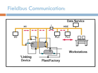
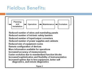
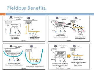
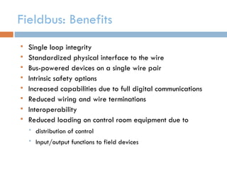
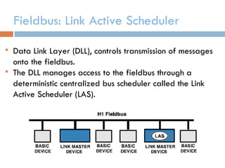
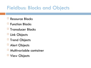
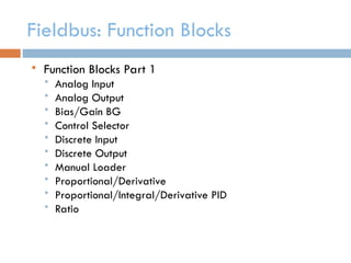
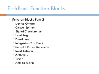
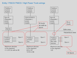
FIELDBUS
Communication Standard
Fieldbus Communication:
Fieldbus Benefits:
Fieldbus Benefits:
Fieldbus: Benefits
 Single loop integrity
 Standardized physical interface to the wire
 Bus-powered devices on a single wire pair
 Intrinsic safety options
 Increased capabilities due to full digital communications
 Reduced wiring and wire terminations
 Interoperability
 Reduced loading on control room equipment due to
 distribution of control
 Input/output functions to field devices
Fieldbus: Signals
 Manchester coded baseband signal
Logical “0” Logical “1”
32 uSec
Transition at 16 uSec
Freq of transmission: 31.25 kHz
Fieldbus: Manchester Signals
Fieldbus: Closed Loop
Fieldbus: Macrocycle
 Macrocycle: Single iteration of schedule within device.
Typical Macrocycle time: 250 ms, 500 ms, 1 sec, 2 sec, and 5 sec.
Fieldbus: Link Active Scheduler
 Data Link Layer (DLL), controls transmission of messages
onto the fieldbus.
 The DLL manages access to the fieldbus through a
deterministic centralized bus scheduler called the Link
Active Scheduler (LAS).
Fieldbus: Blocks and Objects
 Resource Blocks
 Function Blocks
 Transducer Blocks
 Link Objects
 Trend Objects
 Alert Objects
 Multivariable container
 View Objects
Fieldbus: Function Blocks
 Function Blocks Part 1
 Analog Input
 Analog Output
 Bias/Gain BG
 Control Selector
 Discrete Input
 Discrete Output
 Manual Loader
 Proportional/Derivative
 Proportional/Integral/Derivative PID
 Ratio
Fieldbus: Function Blocks
 Function Blocks Part 2
 Device Control
 Output Splitter
 Signal Characterizer
 Lead Lag
 Dead time
 Integrator (Totalizer)
 Setpoint Ramp Generator
 Input Selector
 Arithmetic
 Timer
 Analog Alarm
Fieldbus: Function Block Linking
Fieldbus: View Objects
VIEW 1 - Operation Dynamic
VIEW 2 - Operation Static
VIEW3 - All Dynamic - Detailed
display
VIEW 4 -Configuration and
maintenance info.
Fieldbus: Device Definition
DLL: Scheduled Communication
DLL: Unscheduled Communication
FAS: Virtual Communication Relationship
 Client Server VCRs:
 queued, unscheduled, user initiated, one to one
communication
 Used for Setpoint changes, tuning parameters, Alarm
ACK, device upload or download.
 Report Distribution VCRs:
 Alarm Reports
 Trend Reports
FAS: Virtual Communication Relationship
 Publisher/Subscriber VCR Type
 Buffered, one-to-many communications.
 Devices that wish to receive the Published message are
called “Subscribers.”
 High Speed communication between devices.
 Highest priority
Summary of VCRs:
Fieldbus: Wiring and Installation
FISCO parameters
FISCO: Fieldbus Intrinsic Safety COncept
Entity / FISCO/ FNICO / High Power Trunk wirings
Fieldbus
Control
System
Non-IS
(Repeater )
power
supply
Barrier
Fieldbus
Control
System
Spur-1
Spur-n
.
.
.
Maximum devices
in the segment
4 In IIC as well as IIB
Fieldbus
Control
System
FISCO/FNICO
(Repeater )
power
supply
Fieldbus
junction
box
Spur-1
Spur-n
.
.
.
Maximum devices
in the segment
6/9 in IIC
13/16 in IIB
Fieldbus
Control
System
Non-IS
(Repeater )
power
supply
Fieldbus
junction
Box with
barriers
Spur-1
Spur-n
.
.
.
Maximum devices
in the segment
>25
Safe area
Hazardous area
IS trunk
as well as
spurs
Ex e
trunk
IS Spurs
 Thank you

communication protocol - Foundation Fieldbus Basics.ppt

  • 1.
  • 2.
  • 3.
  • 4.
  • 5.
    Fieldbus: Benefits  Singleloop integrity  Standardized physical interface to the wire  Bus-powered devices on a single wire pair  Intrinsic safety options  Increased capabilities due to full digital communications  Reduced wiring and wire terminations  Interoperability  Reduced loading on control room equipment due to  distribution of control  Input/output functions to field devices
  • 6.
    Fieldbus: Signals  Manchestercoded baseband signal Logical “0” Logical “1” 32 uSec Transition at 16 uSec Freq of transmission: 31.25 kHz
  • 7.
  • 8.
  • 9.
    Fieldbus: Macrocycle  Macrocycle:Single iteration of schedule within device. Typical Macrocycle time: 250 ms, 500 ms, 1 sec, 2 sec, and 5 sec.
  • 10.
    Fieldbus: Link ActiveScheduler  Data Link Layer (DLL), controls transmission of messages onto the fieldbus.  The DLL manages access to the fieldbus through a deterministic centralized bus scheduler called the Link Active Scheduler (LAS).
  • 11.
    Fieldbus: Blocks andObjects  Resource Blocks  Function Blocks  Transducer Blocks  Link Objects  Trend Objects  Alert Objects  Multivariable container  View Objects
  • 12.
    Fieldbus: Function Blocks Function Blocks Part 1  Analog Input  Analog Output  Bias/Gain BG  Control Selector  Discrete Input  Discrete Output  Manual Loader  Proportional/Derivative  Proportional/Integral/Derivative PID  Ratio
  • 13.
    Fieldbus: Function Blocks Function Blocks Part 2  Device Control  Output Splitter  Signal Characterizer  Lead Lag  Dead time  Integrator (Totalizer)  Setpoint Ramp Generator  Input Selector  Arithmetic  Timer  Analog Alarm
  • 14.
  • 15.
    Fieldbus: View Objects VIEW1 - Operation Dynamic VIEW 2 - Operation Static VIEW3 - All Dynamic - Detailed display VIEW 4 -Configuration and maintenance info.
  • 16.
  • 17.
  • 18.
  • 19.
    FAS: Virtual CommunicationRelationship  Client Server VCRs:  queued, unscheduled, user initiated, one to one communication  Used for Setpoint changes, tuning parameters, Alarm ACK, device upload or download.  Report Distribution VCRs:  Alarm Reports  Trend Reports
  • 20.
    FAS: Virtual CommunicationRelationship  Publisher/Subscriber VCR Type  Buffered, one-to-many communications.  Devices that wish to receive the Published message are called “Subscribers.”  High Speed communication between devices.  Highest priority
  • 21.
  • 22.
  • 23.
  • 24.
  • 25.
    FISCO parameters FISCO: FieldbusIntrinsic Safety COncept
  • 26.
    Entity / FISCO/FNICO / High Power Trunk wirings Fieldbus Control System Non-IS (Repeater ) power supply Barrier Fieldbus Control System Spur-1 Spur-n . . . Maximum devices in the segment 4 In IIC as well as IIB Fieldbus Control System FISCO/FNICO (Repeater ) power supply Fieldbus junction box Spur-1 Spur-n . . . Maximum devices in the segment 6/9 in IIC 13/16 in IIB Fieldbus Control System Non-IS (Repeater ) power supply Fieldbus junction Box with barriers Spur-1 Spur-n . . . Maximum devices in the segment >25 Safe area Hazardous area IS trunk as well as spurs Ex e trunk IS Spurs
  • 27.