Downloaded 697 times

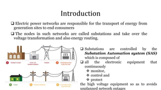
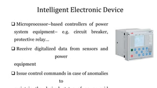
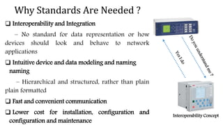
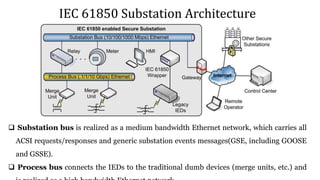
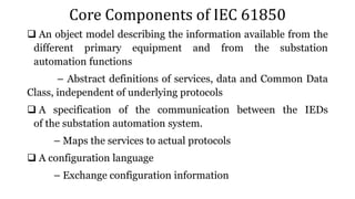
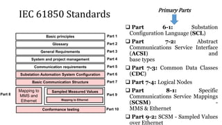
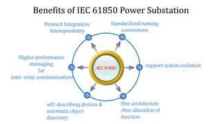
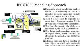
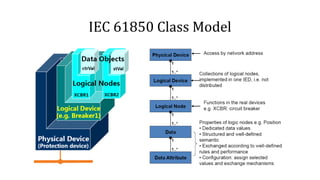
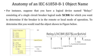
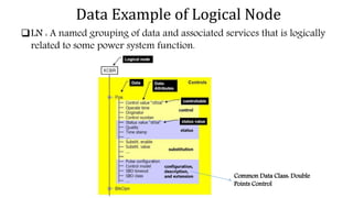
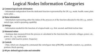
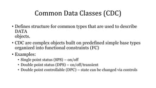
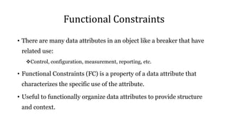
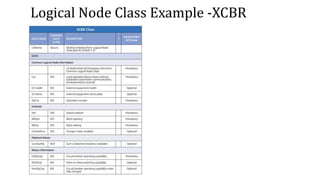
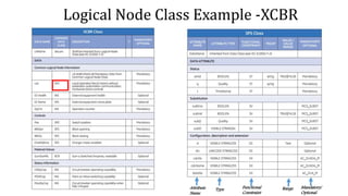
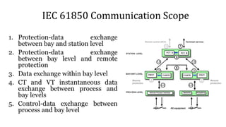
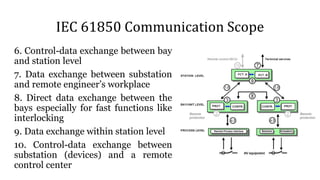

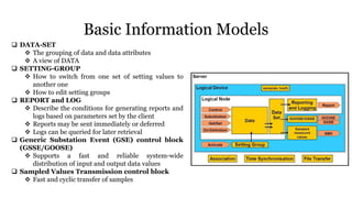
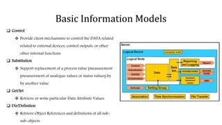
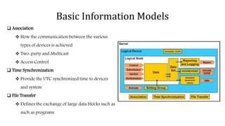
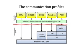
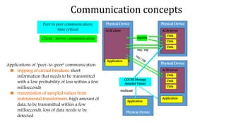
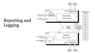
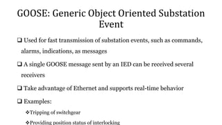
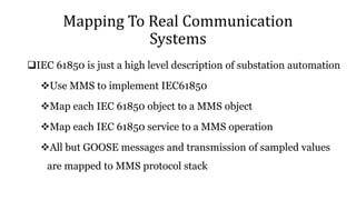
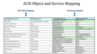
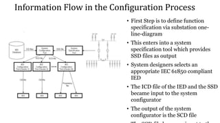
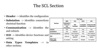
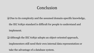

The document discusses the IEC 61850 standard for substation automation, highlighting its key components like the data and service model, communication protocols, and the configuration language (SCL). It emphasizes the need for interoperability and structured device communication in power systems, as well as the benefits of implementing this standard such as enhanced performance and reduced installation costs. Additionally, the document covers the hierarchical modeling of logical nodes and detailed communication processes necessary for efficiently managing electric power networks.