Downloaded 331 times
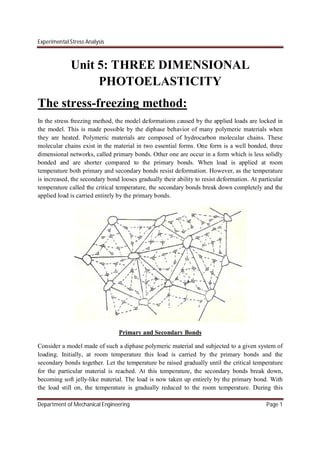
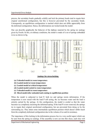

1. The stress-freezing method locks in deformations caused by applied loads in a diphase polymeric material by using its property of secondary bonds breaking down at the critical temperature. 2. Scattered light polariscopes use the phenomenon that light scattered within a photoelastic model is plane-polarized perpendicular to the incident beam direction, allowing visualization of stress information without slicing the model. 3. Scattered light can act as an interior polarizer or analyzer by resolving the polarized scattered light into components along principal stress directions, allowing measurement of stress differences over interior planes using fringe patterns.


