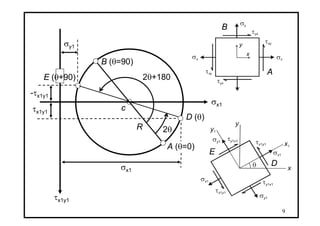
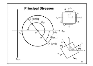
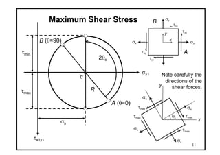
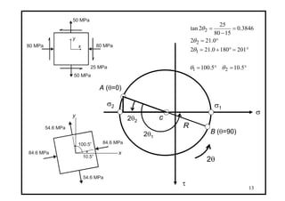
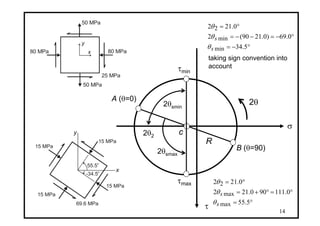
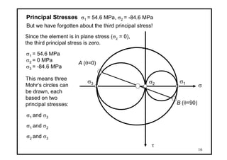
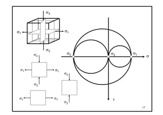
1) The document discusses Mohr's circle for analyzing stresses in plane stress, including how to construct Mohr's circle, determine principal stresses and maximum shear stresses, and stresses on inclined planes.
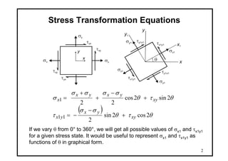
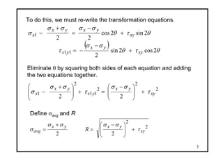
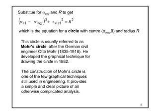
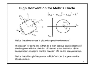
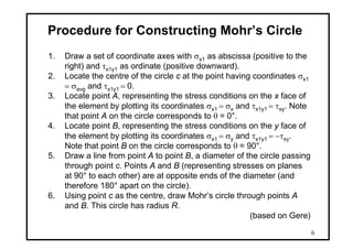
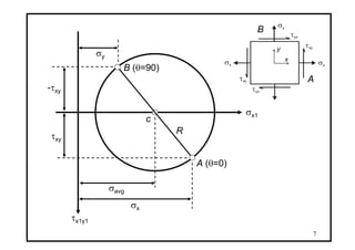
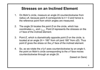
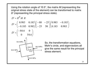
2) It provides the equations for transforming stresses between reference frames and deriving Mohr's circle.
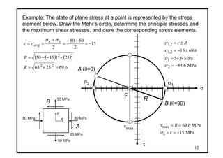
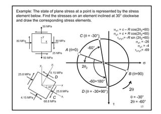
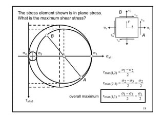
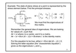
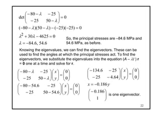
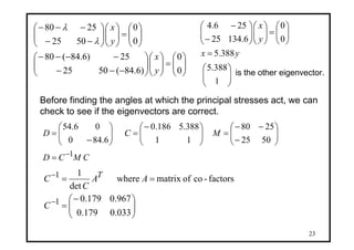
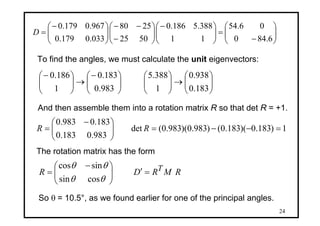
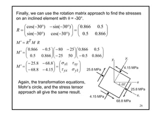
3) An example is worked through applying Mohr's circle to determine stresses for a given stress element.
Lecture slides on the calculation of the bending stress in case of unsymmetrical bending. The Mohr's circle is used to determine the principal second moments of area.
Class notes of Geotechnical Engineering course I used to teach at UET Lahore. Feel free to download the slide show.
Anyone looking to modify these files and use them for their own teaching purposes can contact me directly to get hold of editable version.
Class notes of Geotechnical Engineering course I used to teach at UET Lahore. Feel free to download the slide show.
Anyone looking to modify these files and use them for their own teaching purposes can contact me directly to get hold of editable version.
This book is intended to cover the basic Strength of Materials of the first
two years of an engineering degree or diploma course ; it does not attempt
to deal with the more specialized topics which usually comprise the final
year of such courses.
The work has been confined to the mathematical aspect of the subject
and no descriptive matter relating to design or materials testing has been
included.
Solution manual for introduction to finite element analysis and design nam ...Salehkhanovic
Solution Manual for Introduction to Finite Element Analysis and Design
Author(s) : Nam-Ho Kim and Bhavani V. Sankar
This solution manual include all problems (Chapters 0 to 8) of textbook.
Safalta Digital marketing institute in Noida, provide complete applications that encompass a huge range of virtual advertising and marketing additives, which includes search engine optimization, virtual communication advertising, pay-per-click on marketing, content material advertising, internet analytics, and greater. These university courses are designed for students who possess a comprehensive understanding of virtual marketing strategies and attributes.Safalta Digital Marketing Institute in Noida is a first choice for young individuals or students who are looking to start their careers in the field of digital advertising. The institute gives specialized courses designed and certification.
for beginners, providing thorough training in areas such as SEO, digital communication marketing, and PPC training in Noida. After finishing the program, students receive the certifications recognised by top different universitie, setting a strong foundation for a successful career in digital marketing.
Model Attribute Check Company Auto PropertyCeline George
In Odoo, the multi-company feature allows you to manage multiple companies within a single Odoo database instance. Each company can have its own configurations while still sharing common resources such as products, customers, and suppliers.
A Strategic Approach: GenAI in EducationPeter Windle
Artificial Intelligence (AI) technologies such as Generative AI, Image Generators and Large Language Models have had a dramatic impact on teaching, learning and assessment over the past 18 months. The most immediate threat AI posed was to Academic Integrity with Higher Education Institutes (HEIs) focusing their efforts on combating the use of GenAI in assessment. Guidelines were developed for staff and students, policies put in place too. Innovative educators have forged paths in the use of Generative AI for teaching, learning and assessments leading to pockets of transformation springing up across HEIs, often with little or no top-down guidance, support or direction.
This Gasta posits a strategic approach to integrating AI into HEIs to prepare staff, students and the curriculum for an evolving world and workplace. We will highlight the advantages of working with these technologies beyond the realm of teaching, learning and assessment by considering prompt engineering skills, industry impact, curriculum changes, and the need for staff upskilling. In contrast, not engaging strategically with Generative AI poses risks, including falling behind peers, missed opportunities and failing to ensure our graduates remain employable. The rapid evolution of AI technologies necessitates a proactive and strategic approach if we are to remain relevant.
Francesca Gottschalk - How can education support child empowerment.pptxEduSkills OECD
Francesca Gottschalk from the OECD’s Centre for Educational Research and Innovation presents at the Ask an Expert Webinar: How can education support child empowerment?
2024.06.01 Introducing a competency framework for languag learning materials ...Sandy Millin
http://sandymillin.wordpress.com/iateflwebinar2024
Published classroom materials form the basis of syllabuses, drive teacher professional development, and have a potentially huge influence on learners, teachers and education systems. All teachers also create their own materials, whether a few sentences on a blackboard, a highly-structured fully-realised online course, or anything in between. Despite this, the knowledge and skills needed to create effective language learning materials are rarely part of teacher training, and are mostly learnt by trial and error.
Knowledge and skills frameworks, generally called competency frameworks, for ELT teachers, trainers and managers have existed for a few years now. However, until I created one for my MA dissertation, there wasn’t one drawing together what we need to know and do to be able to effectively produce language learning materials.
This webinar will introduce you to my framework, highlighting the key competencies I identified from my research. It will also show how anybody involved in language teaching (any language, not just English!), teacher training, managing schools or developing language learning materials can benefit from using the framework.
This slide is special for master students (MIBS & MIFB) in UUM. Also useful for readers who are interested in the topic of contemporary Islamic banking.
Unit 8 - Information and Communication Technology (Paper I).pdfThiyagu K
This slides describes the basic concepts of ICT, basics of Email, Emerging Technology and Digital Initiatives in Education. This presentations aligns with the UGC Paper I syllabus.
A review of the growth of the Israel Genealogy Research Association Database Collection for the last 12 months. Our collection is now passed the 3 million mark and still growing. See which archives have contributed the most. See the different types of records we have, and which years have had records added. You can also see what we have for the future.
Executive Directors Chat Leveraging AI for Diversity, Equity, and InclusionTechSoup
Let’s explore the intersection of technology and equity in the final session of our DEI series. Discover how AI tools, like ChatGPT, can be used to support and enhance your nonprofit's DEI initiatives. Participants will gain insights into practical AI applications and get tips for leveraging technology to advance their DEI goals.
Macroeconomics- Movie Location
This will be used as part of your Personal Professional Portfolio once graded.
Objective:
Prepare a presentation or a paper using research, basic comparative analysis, data organization and application of economic information. You will make an informed assessment of an economic climate outside of the United States to accomplish an entertainment industry objective.
1. 1
P4 Stress and Strain Dr. A.B. Zavatsky
HT08
Lecture 6
Mohr’s Circle for Plane Stress
Transformation equations for plane stress.
Procedure for constructing Mohr’s circle.
Stresses on an inclined element.
Principal stresses and maximum shear stresses.
Introduction to the stress tensor.
2. 2
Stress Transformation Equations
σx σx
σy
τxy
τyx
τxy
τyx
x
y
x
y
σx1
θ
y1
x1
σx1
σy1
σy1
τx y1 1
τy x1 1
τx y1 1
τy x1 1
( ) θτθ
σσ
τ
θτθ
σσσσ
σ
2cos2sin
2
2sin2cos
22
11
1
xy
yx
yx
xy
yxyx
x
+
−
−=
+
−
+
+
=
If we vary θ from 0° to 360°, we will get all possible values of σx1 and τx1y1
for a given stress state. It would be useful to represent σx1 and τx1y1 as
functions of θ in graphical form.
3. 3
To do this, we must re-write the transformation equations.
( ) θτθ
σσ
τ
θτθ
σσσσ
σ
2cos2sin
2
2sin2cos
22
11
1
xy
yx
yx
xy
yxyx
x
+
−
−=
+
−
=
+
−
Eliminate θ by squaring both sides of each equation and adding
the two equations together.
2
2
2
11
2
1
22
xy
yx
yx
yx
x τ
σσ
τ
σσ
σ +⎟
⎟
⎠
⎞
⎜
⎜
⎝
⎛ −
=+⎟
⎟
⎠
⎞
⎜
⎜
⎝
⎛ +
−
Define σavg and R
2
2
22
xy
yxyx
avg R τ
σσσσ
σ +⎟
⎟
⎠
⎞
⎜
⎜
⎝
⎛ −
=
+
=
4. 4
Substitue for σavg and R to get
( ) 22
11
2
1 Ryxavgx =+− τσσ
which is the equation for a circle with centre (σavg,0) and radius R.
This circle is usually referred to as
Mohr’s circle, after the German civil
engineer Otto Mohr (1835-1918). He
developed the graphical technique for
drawing the circle in 1882.
The construction of Mohr’s circle is
one of the few graphical techniques
still used in engineering. It provides
a simple and clear picture of an
otherwise complicated analysis.
5. 5
Sign Convention for Mohr’s Circle
x
y
σx1
θ
y1
x1
σx1
σy1
σy1
τx y1 1
τy x1 1
τx y1 1
τy x1 1
( ) 22
11
2
1 Ryxavgx =+− τσσ
σx1
τx1y1
R
2θ
σavg
Notice that shear stress is plotted as positive downward.
The reason for doing this is that 2θ is then positive counterclockwise,
which agrees with the direction of 2θ used in the derivation of the
tranformation equations and the direction of θ on the stress element.
Notice that although 2θ appears in Mohr’s circle, θ appears on the
stress element.
6. 6
Procedure for Constructing Mohr’s Circle
1. Draw a set of coordinate axes with σx1 as abscissa (positive to the
right) and τx1y1 as ordinate (positive downward).
2. Locate the centre of the circle c at the point having coordinates σx1
= σavg and τx1y1 = 0.
3. Locate point A, representing the stress conditions on the x face of
the element by plotting its coordinates σx1 = σx and τx1y1 = τxy. Note
that point A on the circle corresponds to θ = 0°.
4. Locate point B, representing the stress conditions on the y face of
the element by plotting its coordinates σx1 = σy and τx1y1 = −τxy.
Note that point B on the circle corresponds to θ = 90°.
5. Draw a line from point A to point B, a diameter of the circle passing
through point c. Points A and B (representing stresses on planes
at 90° to each other) are at opposite ends of the diameter (and
therefore 180° apart on the circle).
6. Using point c as the centre, draw Mohr’s circle through points A
and B. This circle has radius R.
(based on Gere)
8. 8
Stresses on an Inclined Element
1. On Mohr’s circle, measure an angle 2θ counterclockwise from
radius cA, because point A corresponds to θ = 0 and hence is
the reference point from which angles are measured.
2. The angle 2θ locates the point D on the circle, which has
coordinates σx1 and τx1y1. Point D represents the stresses on the
x1 face of the inclined element.
3. Point E, which is diametrically opposite point D on the circle, is
located at an angle 2θ + 180° from cA (and 180° from cD). Thus
point E gives the stress on the y1 face of the inclined element.
4. So, as we rotate the x1y1 axes counterclockwise by an angle θ,
the point on Mohr’s circle corresponding to the x1 face moves
counterclockwise through an angle 2θ.
(based on Gere)
11. 11
Maximum Shear Stress
σx σx
σy
τxy
τyx
τxy
τyx
x
y
A (θ=0)
σx1
τx1y1
c
R
B (θ=90)
A
B
2θs
σs
τmax
τmin
x
y
σs
θs
σs
σs
σs
τmaxτmax
τmax
τmax
Note carefully the
directions of the
shear forces.
12. 12
Example: The state of plane stress at a point is represented by the stress
element below. Draw the Mohr’s circle, determine the principal stresses and
the maximum shear stresses, and draw the corresponding stress elements.
80 MPa 80 MPa
50 MPa
x
y
50 MPa
25 MPa
σ
τ
15
2
5080
2
−=
+−
=
+
==
yx
avgc
σσ
σ
c
A (θ=0)
A
B (θ=90)B
( )( ) ( )
6.692565
251550
22
22
=+=
+−−=
R
R
R
σ1
σ2
MPa6.84
MPa6.54
6.6915
2
1
2,1
2,1
−=
=
±−=
±=
σ
σ
σ
σ Rc
τmax
MPa15
MPa6.69
s
max
−==
==
c
R
σ
τ
13. 13
84.6 MPa
84.6 MPa
54.6 MPa
x
y
54.6 MPa
10.5o
100.5
o
σ
τ
c
A (θ=0)
B (θ=90)
R
80 MPa 80 MPa
50 MPa
x
y
50 MPa
25 MPa
σ1
σ2
2θ2
2θ1
°=°=
°=°+=
°=
=
−
=
5.105.100
2011800.212
0.212
3846.0
1580
25
2tan
21
1
2
2
θθ
θ
θ
θ
2θ
14. 14
σ
τ
c
A (θ=0)
B (θ=90)
R
80 MPa 80 MPa
50 MPa
x
y
50 MPa
25 MPa
2θ2
2θ
15 MPa
15 MPa
15 MPa
x
y
15 MPa
69.6 MPa
-34.5o
55.5
o
2θsmax
°=
°=°+=
°=
5.55
0.111900.212
0.212
max
max
2
s
s
θ
θ
θ
2θsmin
taking sign convention into
account
°−=
°−=−−=
°=
5.34
0.69)0.2190(2
0.212
min
min
2
s
s
θ
θ
θ
τmax
τmin
15. 15
80 MPa 80 MPa
50 MPa
x
y
50 MPa
25 MPa
A (θ=0)
σ
τ
B (θ=90)25.8 MPa
25.8 MPa
4.15 MPa
x
y
4.15 MPa
68.8 MPa
x1
y1
-30
o
Example: The state of plane stress at a point is represented by the stress
element below. Find the stresses on an element inclined at 30° clockwise
and draw the corresponding stress elements.
-60°
-60+180°
C (θ = -30°)
C
D (θ = -30+90°)
D
2θ2
σx1 = c – R cos(2θ2+60)
σy1 = c + R cos(2θ2+60)
τx1y1= -R sin (2θ2+60)
σx1 = -26
σy1 = -4
τx1y1= -69
2θ
θ = -30°
2θ = -60°
16. 16
σ
τ
A (θ=0)
B (θ=90)
Principal Stresses σ1 = 54.6 MPa, σ2 = -84.6 MPa
But we have forgotten about the third principal stress!
Since the element is in plane stress (σz = 0),
the third principal stress is zero.
σ1 = 54.6 MPa
σ2 = 0 MPa
σ3 = -84.6 MPa
σ1σ2σ3
This means three
Mohr’s circles can
be drawn, each
based on two
principal stresses:
σ1 and σ3
σ1 and σ2
σ2 and σ3
18. 18
σx σx
σy
τxy
τyx
τxy
τyx
x
y
The stress element shown is in plane stress.
What is the maximum shear stress?
A
B
σx1
τx1y1
A
B
σ3 σ1σ2
22
131
)3,1max(
σσσ
τ =
−
=
2
21
)2,1max(
σσ
τ
−
=
22
232
)3,2max(
σσσ
τ =
−
=
overall maximum
20. 20
From our analyses so far, we know that for a given stress system,
it is possible to find a set of three principal stresses. We also know
that if the principal stresses are acting, the shear stresses must be
zero. In terms of the stress tensor,
⎟⎟
⎟
⎟
⎠
⎞
⎜⎜
⎜
⎜
⎝
⎛
zzzyzx
yzyyyx
xzxyxx
σττ
τστ
ττσ
⎟
⎟
⎟
⎠
⎞
⎜
⎜
⎜
⎝
⎛
3
2
1
00
00
00
σ
σ
σ
In mathematical terms, this is the process of matrix diagonaliza-
tion in which the eigenvalues of the original matrix are just the
principal stresses.
21. 21
80 MPa 80 MPa
50 MPa
x
y
50 MPa
25 MPa
Example: The state of plane stress at a point is represented by the
stress element below. Find the principal stresses.
⎟⎟
⎠
⎞
⎜⎜
⎝
⎛
−
−−
=⎟
⎟
⎠
⎞
⎜
⎜
⎝
⎛
=
5025
2580
yyx
xyx
M
στ
τσ
We must find the eigenvalues of
this matrix.
Remember the general idea of eigenvalues. We are looking
for values of λ such that:
Ar = λr where r is a vector, and A is a matrix.
Ar – λr = 0 or (A – λI) r = 0 where I is the identity matrix.
For this equation to be true, either r = 0 or det (A – λI) = 0.
Solving the latter equation (the “characteristic equation”)
gives us the eigenvalues λ1 and λ2.
22. 22
6.54,6.84
0462530
0)25)(25()50)(80(
0
5025
2580
det
2
−=
=−+
=−−−−−−
=⎟⎟
⎠
⎞
⎜⎜
⎝
⎛
−−
−−−
λ
λλ
λλ
λ
λ
So, the principal stresses are –84.6 MPa and
54.6 MPa, as before.
Knowing the eigenvalues, we can find the eigenvectors. These can be
used to find the angles at which the principal stresses act. To find the
eigenvectors, we substitute the eigenvalues into the equation (A – λI ) r
= 0 one at a time and solve for r.
⎟⎟
⎠
⎞
⎜⎜
⎝
⎛
=⎟⎟
⎠
⎞
⎜⎜
⎝
⎛
⎟⎟
⎠
⎞
⎜⎜
⎝
⎛
−−
−−−
⎟⎟
⎠
⎞
⎜⎜
⎝
⎛
=⎟⎟
⎠
⎞
⎜⎜
⎝
⎛
⎟⎟
⎠
⎞
⎜⎜
⎝
⎛
−−
−−−
0
0
6.545025
256.5480
0
0
5025
2580
y
x
y
x
λ
λ
⎟⎟
⎠
⎞
⎜⎜
⎝
⎛−
−=
⎟⎟
⎠
⎞
⎜⎜
⎝
⎛
=⎟⎟
⎠
⎞
⎜⎜
⎝
⎛
⎟⎟
⎠
⎞
⎜⎜
⎝
⎛
−−
−−
1
186.0
186.0
0
0
64.425
256.134
yx
y
x
is one eigenvector.
24. 24
⎟⎟
⎠
⎞
⎜⎜
⎝
⎛
−
=⎟⎟
⎠
⎞
⎜⎜
⎝
⎛−
⎟⎟
⎠
⎞
⎜⎜
⎝
⎛
−
−−
⎟⎟
⎠
⎞
⎜⎜
⎝
⎛−
=
6.840
06.54
11
388.5186.0
5025
2580
033.0179.0
967.0179.0
D
To find the angles, we must calculate the unit eigenvectors:
⎟⎟
⎠
⎞
⎜⎜
⎝
⎛
→⎟⎟
⎠
⎞
⎜⎜
⎝
⎛
⎟⎟
⎠
⎞
⎜⎜
⎝
⎛−
→⎟⎟
⎠
⎞
⎜⎜
⎝
⎛−
183.0
938.0
1
388.5
983.0
183.0
1
186.0
And then assemble them into a rotation matrix R so that det R = +1.
1)183.0)(183.0()983.0)(983.0(det
983.0183.0
183.0983.0
=−−=⎟⎟
⎠
⎞
⎜⎜
⎝
⎛ −
= RR
RMRDR T=′⎟⎟
⎠
⎞
⎜⎜
⎝
⎛ −
=
θθ
θθ
cossin
sincos
The rotation matrix has the form
So θ = 10.5°, as we found earlier for one of the principal angles.