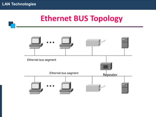
EC8551 Communication Networks
ETHERNET(802.3)
INTRODUCTION
• Ethernet is a multiple access network which means a
collection of nodes transmit and receive data frames
through a shared link
• It was first widely used high speed LAN.
• It is like a bus that has multiple stations plugged into it
Reasons for Ethernet Success
• Ethernet is the most successful local area networking
technology.
• It designed to used in Full duplex ,point to point
configuration that means used in switch network.
• Easy to administer and maintain.
Ethernet
• An Ethernet segment is implemented on a coaxial cable of up to 500 m.
– This cable is similar to the type used for cable TV except that it
typically has an impedance of 50 ohms instead of cable TV’s 75
ohms.
• Hosts connect to an Ethernet segment by tapping into it.
• A transceiver (a small device directly attached to the tap) detects when
the line is idle and drives signal when the host is transmitting.
• The transceiver also receives incoming signal.
• The transceiver is connected to an Ethernet adaptor which is plugged
into the host.
• The protocol is implemented on the adaptor.
Ethernet
Ethernet transceiver and adaptor
Ethernet
• Multiple Ethernet segments can be joined together by
repeaters.
• A repeater is a device that forwards digital signals.
• No more than four repeaters may be positioned
between any pair of hosts.
– An Ethernet has a total reach of only 2500 m.
Ethernet
Ethernet repeater
Ethernet BUS Topology
LAN Technologies
Repeater
Ethernet STAR Topology
LAN Technologies
Hub
Ethernet
• Any signal placed on the Ethernet by a host is
broadcast over the entire network
– Signal is propagated in both directions.
– Repeaters forward the signal on all outgoing segments.
– Terminators attached to the end of each segment absorb
the signal.
• Ethernet uses Manchester encoding scheme.
Encoding in a Standard Ethernet implementation
CSMA/CD
• Carrier sense means all the nodes can
distinguish between an idle and busy link.
• Collision detect means a node can listens
when a frame which is transmitted has
collided with a frame transmitted by
another node.
Receiver Algorithm
• Each frame transmitted on an Ethernet is
received by every adaptor connected to that
Ethernet.
• Ethernet receives broadcast frames, frames
addressed to it and multicast frames if it
belongs to that group. Otherwise frames are
discarded
Transmitter Algorithm
Ethernet follows Carrier Sense Multiple Access
with Collision Detect (CSMA/CD) Ethernet is
said to be a 1-persistent protocol. When the
adaptor has a frame to send:
If line is idle, it transmits the frame
immediately.
If line is busy, it waits for the line to go idle and
then transmits immediately. It is possible for two
(or more) adaptors to begin transmitting at the
same time.
Ethernet evolution through four generations
802.3 MAC frame
Preamble—contains 7 bytes of alternating 0s and 1s that alerts the receiving
system and enables it to synchronize its input timing.
Start frame delimiter—the second field (10101011) signals the beginning of
the frame.
Destination address—the 6 bytes contains the physical address of the
destination station or stations to receive the packet.
Source address—the 6 bytes contains the physical address of the sender of the
packet.
Length/type—it either represents length or type of the upper layer protocol.
Minimum frame length is 64 bytes. This restriction is required for operation of
CSMA/CD.
Data—this field carries data encapsulated from the upper-layer protocols. It is
minimum of 46 and a maximum of 1500 bytes.
CRC—the last field contains error detection information (CRC-32 )
Frame length:
Minimum: 64 bytes (512 bits)
Maximum: 1518 bytes (12,144 bits)
Note
Why the minimum frame length in Ethernet should
be at least 64 bytes?
• Host A begins transmitting a frame at time t, as shown in (a).
• It takes one link latency (say d) for the frame to reach host B. Thus, the
first bit of A’s frame arrives at B at time t + d, as shown in (b).
• Suppose an instant before host A’s frame arrives, B senses it idle line,
host B begins to transmit its own frame.
• B’s frame will immediately collide with A’s frame, and this collision
will be detected by host B (c). Host B will send the 32-bit jamming
sequence.
• Host A will not know that the collision occurred until B’s frame reaches
it, i.e., at time t + 2d, as shown in (d).
• On a maximally configured Ethernet, the round-trip delay is 51.2 µs,
i.e., 512 bits (64 bytes)
•
Addressing
• Each station on an Ethernet network has its own
NIC
• The NIC fits inside the station and provides the
station with a 6 bytes physical address.
• Ethernet address written in Hexadecimal.
with colon between the bytes.
Example of an Ethernet address in hexadecimal notation
Unicast, Multicast and Broadcast
• A source address is always a unicast address
that frame comes from always one station.
• The Destination address can be unicast, multicast
and broadcast.
The least significant bit of the first byte
defines the type of address.
If the bit is 0, the address is unicast;
otherwise, it is multicast.
Note
The broadcast destination address is a
special case of the multicast address in
which all bits are 1s.
Note
Define the type of the following destination addresses:
a. 4A:30:10:21:10:1A b. 47:20:1B:2E:08:EE
c. FF:FF:FF:FF:FF:FF
Solution
To find the type of the address, we need to look at the
second hexadecimal digit from the left. If it is even, the
address is unicast. If it is odd, the address is multicast. If
all digits are F’s, the address is broadcast. Therefore, we
have the following:
a. This is a unicast address because A in binary is 1010.
b. This is a multicast address because 7 in binary is 0111.
c. This is a broadcast address because all digits are F’s.
Example 13.1
Categories of Standard Ethernet
Ethernet Cabling
10 base 5: popularly said thick Ethernet
Advantage: Disadvantage:
Noise Immunity Inflexible
Long Distance possible Fault Intolerant
Conceptually simple

32
10Base2 implementation Thin Ethernet
Advantage: Disadvantage :
Relatively Inexpensive suited to small networks
10Base-T implementation
10Base-F implementation
Table Summary of Standard Ethernet implementations
CHANGES IN THE STANDARD
The 10-Mbps Standard Ethernet has gone through
several changes before moving to the higher data rates.
These changes actually opened the road to the evolution
of the Ethernet to become compatible with other high-
data-rate LANs.
Bridged Ethernet
Switched Ethernet
Full-Duplex Ethernet
Topics discussed in this section:
Bridge effect on Ethernet
Raise the bandwidth
• Each network has a capacity of 10 Mbps. The l0-Mbps
capacity in each segment is now shared between 6
stations. In a network with a heavy load, each station
theoretically is offered 10/6 Mbps instead of 10/12 Mbps
Separate collision domains
• Without bridging, 12 stations contend for access
to the medium; with bridging only 3 stations
contend for access to the medium
A network with and without a bridge
Collision domains in an unbridged network and a bridged network
Switched Ethernet
Full-duplex switched Ethernet
TEXT BOOK:
Behrouz A. Forouzan, Data communication and Networking, Fifth Edition, Tata
McGraw – Hill, 2013 (UNIT I –V).
REFERENCES:
James F. Kurose, Keith W. Ross, Computer Networking - A Top-Down Approach
Featuring the Internet, Seventh Edition, Pearson Education, 2016.
Nader. F. Mir, Computer and Communication Networks, Pearson Prentice Hall
Publishers, 2nd Edition, 2014.
Ying-Dar Lin, Ren-Hung Hwang, Fred Baker, Computer Networks: An Open Source
Approach, Mc Graw Hill Publisher, 2011.
Larry L. Peterson, Bruce S. Davie, Computer Networks: A Systems Approach, Fifth
Edition, Morgan Kaufmann Publishers, 2011.

Ethernet 19 20

  • 1.
  • 2.
  • 3.
    INTRODUCTION • Ethernet isa multiple access network which means a collection of nodes transmit and receive data frames through a shared link • It was first widely used high speed LAN. • It is like a bus that has multiple stations plugged into it
  • 4.
    Reasons for EthernetSuccess • Ethernet is the most successful local area networking technology. • It designed to used in Full duplex ,point to point configuration that means used in switch network. • Easy to administer and maintain.
  • 6.
    Ethernet • An Ethernetsegment is implemented on a coaxial cable of up to 500 m. – This cable is similar to the type used for cable TV except that it typically has an impedance of 50 ohms instead of cable TV’s 75 ohms. • Hosts connect to an Ethernet segment by tapping into it. • A transceiver (a small device directly attached to the tap) detects when the line is idle and drives signal when the host is transmitting. • The transceiver also receives incoming signal. • The transceiver is connected to an Ethernet adaptor which is plugged into the host. • The protocol is implemented on the adaptor.
  • 7.
  • 8.
    Ethernet • Multiple Ethernetsegments can be joined together by repeaters. • A repeater is a device that forwards digital signals. • No more than four repeaters may be positioned between any pair of hosts. – An Ethernet has a total reach of only 2500 m.
  • 9.
  • 10.
    Ethernet BUS Topology LANTechnologies Repeater
  • 11.
  • 12.
    Ethernet • Any signalplaced on the Ethernet by a host is broadcast over the entire network – Signal is propagated in both directions. – Repeaters forward the signal on all outgoing segments. – Terminators attached to the end of each segment absorb the signal. • Ethernet uses Manchester encoding scheme.
  • 15.
    Encoding in aStandard Ethernet implementation
  • 16.
    CSMA/CD • Carrier sensemeans all the nodes can distinguish between an idle and busy link. • Collision detect means a node can listens when a frame which is transmitted has collided with a frame transmitted by another node.
  • 17.
    Receiver Algorithm • Eachframe transmitted on an Ethernet is received by every adaptor connected to that Ethernet. • Ethernet receives broadcast frames, frames addressed to it and multicast frames if it belongs to that group. Otherwise frames are discarded
  • 18.
    Transmitter Algorithm Ethernet followsCarrier Sense Multiple Access with Collision Detect (CSMA/CD) Ethernet is said to be a 1-persistent protocol. When the adaptor has a frame to send: If line is idle, it transmits the frame immediately. If line is busy, it waits for the line to go idle and then transmits immediately. It is possible for two (or more) adaptors to begin transmitting at the same time.
  • 19.
  • 20.
  • 21.
    Preamble—contains 7 bytesof alternating 0s and 1s that alerts the receiving system and enables it to synchronize its input timing. Start frame delimiter—the second field (10101011) signals the beginning of the frame. Destination address—the 6 bytes contains the physical address of the destination station or stations to receive the packet. Source address—the 6 bytes contains the physical address of the sender of the packet. Length/type—it either represents length or type of the upper layer protocol. Minimum frame length is 64 bytes. This restriction is required for operation of CSMA/CD. Data—this field carries data encapsulated from the upper-layer protocols. It is minimum of 46 and a maximum of 1500 bytes. CRC—the last field contains error detection information (CRC-32 )
  • 22.
    Frame length: Minimum: 64bytes (512 bits) Maximum: 1518 bytes (12,144 bits) Note
  • 23.
    Why the minimumframe length in Ethernet should be at least 64 bytes?
  • 24.
    • Host Abegins transmitting a frame at time t, as shown in (a). • It takes one link latency (say d) for the frame to reach host B. Thus, the first bit of A’s frame arrives at B at time t + d, as shown in (b). • Suppose an instant before host A’s frame arrives, B senses it idle line, host B begins to transmit its own frame. • B’s frame will immediately collide with A’s frame, and this collision will be detected by host B (c). Host B will send the 32-bit jamming sequence. • Host A will not know that the collision occurred until B’s frame reaches it, i.e., at time t + 2d, as shown in (d). • On a maximally configured Ethernet, the round-trip delay is 51.2 µs, i.e., 512 bits (64 bytes) •
  • 25.
    Addressing • Each stationon an Ethernet network has its own NIC • The NIC fits inside the station and provides the station with a 6 bytes physical address. • Ethernet address written in Hexadecimal. with colon between the bytes.
  • 26.
    Example of anEthernet address in hexadecimal notation
  • 27.
    Unicast, Multicast andBroadcast • A source address is always a unicast address that frame comes from always one station. • The Destination address can be unicast, multicast and broadcast.
  • 28.
    The least significantbit of the first byte defines the type of address. If the bit is 0, the address is unicast; otherwise, it is multicast. Note
  • 29.
    The broadcast destinationaddress is a special case of the multicast address in which all bits are 1s. Note
  • 30.
    Define the typeof the following destination addresses: a. 4A:30:10:21:10:1A b. 47:20:1B:2E:08:EE c. FF:FF:FF:FF:FF:FF Solution To find the type of the address, we need to look at the second hexadecimal digit from the left. If it is even, the address is unicast. If it is odd, the address is multicast. If all digits are F’s, the address is broadcast. Therefore, we have the following: a. This is a unicast address because A in binary is 1010. b. This is a multicast address because 7 in binary is 0111. c. This is a broadcast address because all digits are F’s. Example 13.1
  • 31.
  • 32.
    Ethernet Cabling 10 base5: popularly said thick Ethernet Advantage: Disadvantage: Noise Immunity Inflexible Long Distance possible Fault Intolerant Conceptually simple  32
  • 33.
    10Base2 implementation ThinEthernet Advantage: Disadvantage : Relatively Inexpensive suited to small networks
  • 34.
  • 35.
  • 36.
    Table Summary ofStandard Ethernet implementations
  • 37.
    CHANGES IN THESTANDARD The 10-Mbps Standard Ethernet has gone through several changes before moving to the higher data rates. These changes actually opened the road to the evolution of the Ethernet to become compatible with other high- data-rate LANs. Bridged Ethernet Switched Ethernet Full-Duplex Ethernet Topics discussed in this section:
  • 38.
    Bridge effect onEthernet Raise the bandwidth • Each network has a capacity of 10 Mbps. The l0-Mbps capacity in each segment is now shared between 6 stations. In a network with a heavy load, each station theoretically is offered 10/6 Mbps instead of 10/12 Mbps Separate collision domains • Without bridging, 12 stations contend for access to the medium; with bridging only 3 stations contend for access to the medium
  • 39.
    A network withand without a bridge
  • 40.
    Collision domains inan unbridged network and a bridged network
  • 41.
  • 42.
  • 43.
    TEXT BOOK: Behrouz A.Forouzan, Data communication and Networking, Fifth Edition, Tata McGraw – Hill, 2013 (UNIT I –V). REFERENCES: James F. Kurose, Keith W. Ross, Computer Networking - A Top-Down Approach Featuring the Internet, Seventh Edition, Pearson Education, 2016. Nader. F. Mir, Computer and Communication Networks, Pearson Prentice Hall Publishers, 2nd Edition, 2014. Ying-Dar Lin, Ren-Hung Hwang, Fred Baker, Computer Networks: An Open Source Approach, Mc Graw Hill Publisher, 2011. Larry L. Peterson, Bruce S. Davie, Computer Networks: A Systems Approach, Fifth Edition, Morgan Kaufmann Publishers, 2011.