The document discusses Ethernet and multiple access protocols. It covers:
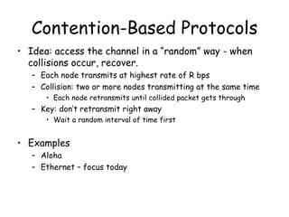
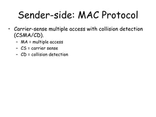
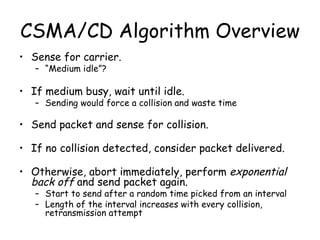
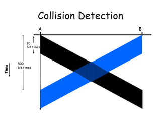
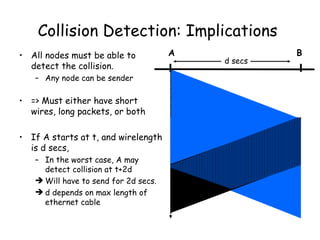
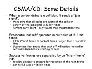
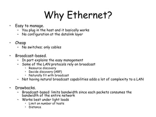
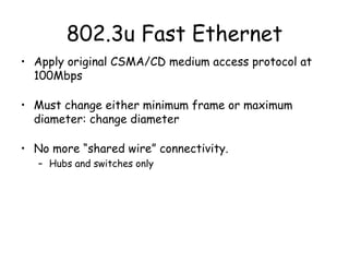
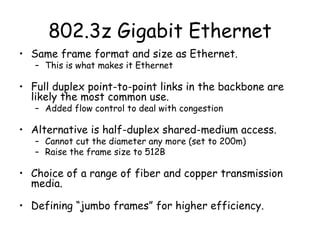
- Ethernet uses CSMA/CD as its multiple access protocol to prevent collisions on shared channels.
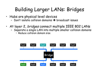
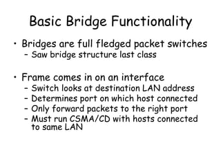
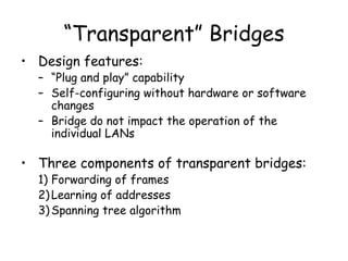
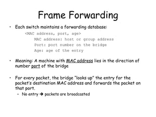
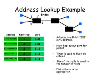
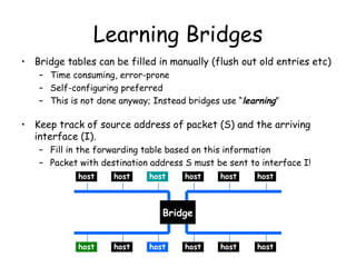
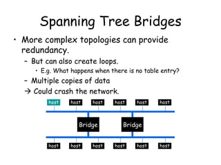
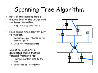
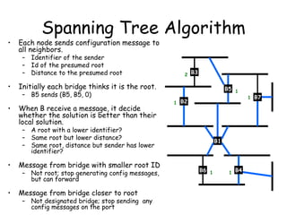
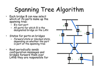
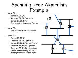
- Bridges connect multiple Ethernet networks and use the spanning tree protocol to prevent loops while maintaining connectivity.
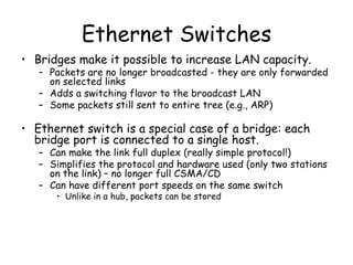
- Switches operate similarly to bridges but each port connects to a single device, allowing for full-duplex links.


![[MS PowerPoint 97/2000 format]](https://cdn.slidesharecdn.com/ss_thumbnails/ms-powerpoint-972000-format2933-thumbnail.jpg?width=640&height=640&fit=bounds)