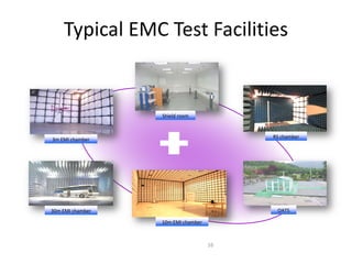
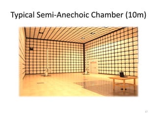
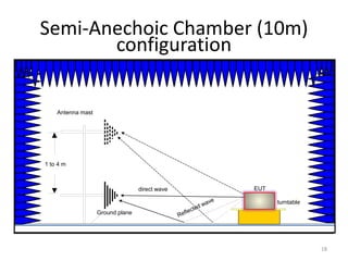
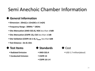
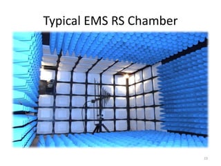
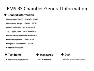
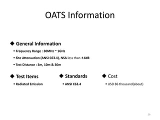
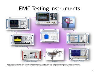
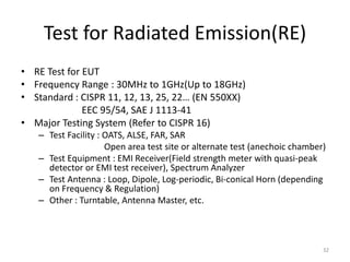
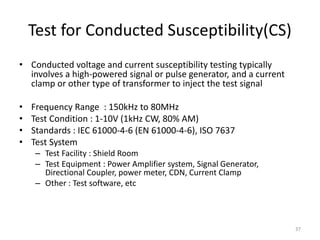
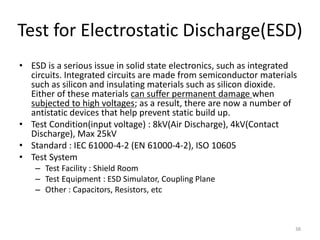
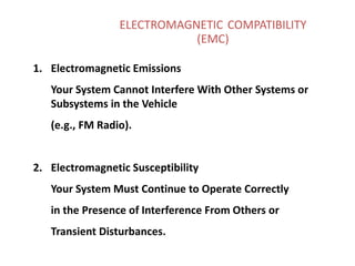
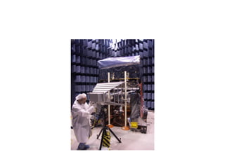
EC6011 ELECTROMAGNETIC INTERFERENCE
AND COMPATIBILITY
Prepared by
Mr.V.Rajesh AP/ECE
Ramco Institute of Technology
Rajapalayam-Tamilnadu.
The radiator was connected
to the special power supply
EMC Problems
Brazil rocket explosion
Alcantara launch center
killing 21 people,
injuring 20 more
2003
Aircraft carrier explosion
USS Forrestal Disaster, Vietnam
July 29, 1967
5
Typical EMC Test Facilities
16
Shield room
3m EMI chamber
RS chamber
30m EMI chamber
10m EMI chamber
OATS
Typical Semi-Anechoic Chamber (10m)
17
Semi-Anechoic Chamber (10m)
configuration
18
1 to 4 m
Antenna mast
Ground plane
EUTdirect wave
turntable
Semi Anechoic Chamber Information
19
 General Information
 Dimension : 20m(L) x 12m(W) x 8.5m(H)
 Frequency Range : 30MHz ~ 18GHz
 Site Attenuation (ANSI C63.4), NSA less than ±4dB
 Site Attenuation (CISPR 13), CSA less than ±3dB
 Site Validation (CISPR 16-1-4), SVSWR less than 6dB
 Test Distance : 3m & 10m
 Test Items
 Radiated Emission
 Conducted Emission
 Standards
 ANSI C63.4
 CISPR 13
 CISPR 16-1-4
 Cost
 USD 1.7 million(about)
Typical EMC test facilities layout(Top view)
20
EMC test facilities construction procedure(1)
21
1. Installation of steel structure 2. Installation of shield panel[Floor] 3. Installation of scaffold
4. Installation of shield panel
[Wall & Ceiling]
5. Installation of Door, Filter 6. Performance [SE Test]
EMC test facilities construction procedure(2)
22
7. Installation of Ferrite Tile 8. Installation of Absorbers 9. Installation of Raised floor
10. Installation of Groundplane 11. Finishing; Floor, interior 12. Performance [NSA Test]
Typical EMS RS Chamber
23
EMS RS Chamber General Information
24
 Cost
 USD 430 thousand(about)
 General Information
 Test Items  Standards
 Dimension : 9m(L) x 6m(W) x 6m(H)
 Frequency Range : 26MHz ~ 18GHz
 Field Uniformity (IEC 61000-4-3)
: (0 ~ 6)dB, over 75% of a surface
 Polarization : Vertical & Horizontal
 Uniformity Plane : 1.5m x 1.5m
 Height of the antenna : 1.55m
 Test Distance : 3m
 Radiated Susceptibility  IEC 61000-4-3
Typical Screen/Shield Rooms
25
Typical Shield Rooms Information
26
 Cost
 USD 260 thousand(about)
 General Information
 Test Items  Standards
 Dimension : 10m(L) x 7.5m(W) x 3m(H)
 Frequency Range : 14kHz ~ 18GHz
 Shielding Effectiveness (IEEE 299)
: more than (60 ~ 100)dB
 Measurement Point : Door, Filter, Ceiling, walls, and ventilator
 Conducted Emission
 Disturbance Power
 ESD/EFT/Surge etc.
 CISPR 14-1/13/22 etc.
Typical Open-Area Test Sites(OATS)
27
OATS Configuration
28
OATS Information
29
 General Information
 Frequency Range : 30MHz ~ 1GHz
 Site Attenuation (ANSI C63.4), NSA less than ±4dB
 Test Distance : 3m, 10m & 30m
 Test Items
 Radiated Emission
 Standards
 ANSI C63.4
 Cost
 USD 86 thousand(about)
EMC Testing Instruments
30
EMI test Receiver
Oscilloscope
Spectrum Analyzer
Signal Generator
Network Analyzer
ESD Generator
EFT/Surge Generator
Above equipments are the most commonly used available for performing EMC measurements.
LISN
Antenna
EMC Tests
31
Test for Radiated Emission(RE)
• RE Test for EUT
• Frequency Range : 30MHz to 1GHz(Up to 18GHz)
• Standard : CISPR 11, 12, 13, 25, 22… (EN 550XX)
EEC 95/54, SAE J 1113-41
• Major Testing System (Refer to CISPR 16)
– Test Facility : OATS, ALSE, FAR, SAR
Open area test site or alternate test (anechoic chamber)
– Test Equipment : EMI Receiver(Field strength meter with quasi-peak
detector or EMI test receiver), Spectrum Analyzer
– Test Antenna : Loop, Dipole, Log-periodic, Bi-conical Horn (depending
on Frequency & Regulation)
– Other : Turntable, Antenna Master, etc.
32
Limit of RE
33
Test for Conducted Emission(CE)
• CE Measurement emitting from cable of EUT
• Frequency Range : 150kHz to 30MHz
• Standards : CISPR 11, 13, 14, 15, 25, 22.. (EN 550XX)
• Testing System (Refer to CISPR 16)
– Test Facility : Shielded Room or adequate ground planes
– Test Equipment : EMI Receiver, Spectrum Analyzer(Quasi-peak Average
detector available)
– Other : LISN, etc.
* LISN (Line Impedance Stabilization Network) :
to create a known impedance on power lines of electrical equipment
during electromagnetic interference testing. A LISN is typically designed to
allow for measurements of the electromagnetic interference existing on
the power line.
34
Limit of CE
35
Conducted Disturbance
at the Mains Ports
* Decreasing Linearly with the Logarithm of the Frequency
- The lower limit shall apply at the transition frequencies.
- Telecommunication Ports 에 대한 Limit 는 고려중임.
0.15 ~ 0.5
0.5 ~ 5
5 ~ 30
79
73
73
66
60
60
Frequency
Range
MHz
Class A
Limits dB (uV)
Q.P Average
Class B
Limits dB (uV)
Q.P Average
66 ~ 56 *
56
60
56 ~ 46
46
50
Table 1 , 2
44
48
52
56
60
64
68
72
76
80
0.1 1 10 100
Disturbance Voltage Injected
into the Mains
Calss A (Q.P)
300.5 5
Calss A (Average)
Calss B (Q.P)
Calss B (Average)
79
73
66
46
50
dBuV
MHz
Test for Radiated Susceptibility(RS)
• Radiated field susceptibility testing typically involves a high-
powered source of RF or EM pulse energy and a radiating
antenna to direct the energy at the potential victim or
device under test (DUT).
• Frequency Range : 80 MHz to 1000 MHz
• Test condition : 1-30 V/m (1 kHz CW, 80% AM) , 100 V/m
• Standards : IEC 61000-4-3 (EN 61000-4-3), ISO 11452-2
• Test Facility : FAR
– Test Equipment : Power Amplifier system, Antenna, Field Probe
Sensor, Signal Generator, Directional Coupler, power meter,
– Other : Test software, etc
36
Test for Conducted Susceptibility(CS)
• Conducted voltage and current susceptibility testing typically
involves a high-powered signal or pulse generator, and a current
clamp or other type of transformer to inject the test signal
• Frequency Range : 150kHz to 80MHz
• Test Condition : 1-10V (1kHz CW, 80% AM)
• Standards : IEC 61000-4-6 (EN 61000-4-6), ISO 7637
• Test System
– Test Facility : Shield Room
– Test Equipment : Power Amplifier system, Signal Generator,
Directional Coupler, power meter, CDN, Current Clamp
– Other : Test software, etc
37
Test for Electrostatic Discharge(ESD)
• ESD is a serious issue in solid state electronics, such as integrated
circuits. Integrated circuits are made from semiconductor materials
such as silicon and insulating materials such as silicon dioxide.
Either of these materials can suffer permanent damage when
subjected to high voltages; as a result, there are now a number of
antistatic devices that help prevent static build up.
• Test Condition(input voltage) : 8kV(Air Discharge), 4kV(Contact
Discharge), Max 25kV
• Standard : IEC 61000-4-2 (EN 61000-4-2), ISO 10605
• Test System
– Test Facility : Shield Room
– Test Equipment : ESD Simulator, Coupling Plane
– Other : Capacitors, Resistors, etc
38
ELECTROMAGNETIC COMPATIBILITY
(EMC)
1. Electromagnetic Emissions
Your System Cannot Interfere With Other Systems or
Subsystems in the Vehicle
(e.g., FM Radio).
2. Electromagnetic Susceptibility
Your System Must Continue to Operate Correctly
in the Presence of Interference From Others or
Transient Disturbances.
EMI/EMC 29
Radiated Susceptibility - TKR
Emi test introduction 2017 18

Emi test introduction 2017 18

  • 1.
    EC6011 ELECTROMAGNETIC INTERFERENCE ANDCOMPATIBILITY Prepared by Mr.V.Rajesh AP/ECE Ramco Institute of Technology Rajapalayam-Tamilnadu.
  • 2.
    The radiator wasconnected to the special power supply
  • 3.
    EMC Problems Brazil rocketexplosion Alcantara launch center killing 21 people, injuring 20 more 2003 Aircraft carrier explosion USS Forrestal Disaster, Vietnam July 29, 1967 5
  • 4.
    Typical EMC TestFacilities 16 Shield room 3m EMI chamber RS chamber 30m EMI chamber 10m EMI chamber OATS
  • 5.
  • 6.
    Semi-Anechoic Chamber (10m) configuration 18 1to 4 m Antenna mast Ground plane EUTdirect wave turntable
  • 7.
    Semi Anechoic ChamberInformation 19  General Information  Dimension : 20m(L) x 12m(W) x 8.5m(H)  Frequency Range : 30MHz ~ 18GHz  Site Attenuation (ANSI C63.4), NSA less than ±4dB  Site Attenuation (CISPR 13), CSA less than ±3dB  Site Validation (CISPR 16-1-4), SVSWR less than 6dB  Test Distance : 3m & 10m  Test Items  Radiated Emission  Conducted Emission  Standards  ANSI C63.4  CISPR 13  CISPR 16-1-4  Cost  USD 1.7 million(about)
  • 8.
    Typical EMC testfacilities layout(Top view) 20
  • 9.
    EMC test facilitiesconstruction procedure(1) 21 1. Installation of steel structure 2. Installation of shield panel[Floor] 3. Installation of scaffold 4. Installation of shield panel [Wall & Ceiling] 5. Installation of Door, Filter 6. Performance [SE Test]
  • 10.
    EMC test facilitiesconstruction procedure(2) 22 7. Installation of Ferrite Tile 8. Installation of Absorbers 9. Installation of Raised floor 10. Installation of Groundplane 11. Finishing; Floor, interior 12. Performance [NSA Test]
  • 11.
    Typical EMS RSChamber 23
  • 12.
    EMS RS ChamberGeneral Information 24  Cost  USD 430 thousand(about)  General Information  Test Items  Standards  Dimension : 9m(L) x 6m(W) x 6m(H)  Frequency Range : 26MHz ~ 18GHz  Field Uniformity (IEC 61000-4-3) : (0 ~ 6)dB, over 75% of a surface  Polarization : Vertical & Horizontal  Uniformity Plane : 1.5m x 1.5m  Height of the antenna : 1.55m  Test Distance : 3m  Radiated Susceptibility  IEC 61000-4-3
  • 13.
  • 14.
    Typical Shield RoomsInformation 26  Cost  USD 260 thousand(about)  General Information  Test Items  Standards  Dimension : 10m(L) x 7.5m(W) x 3m(H)  Frequency Range : 14kHz ~ 18GHz  Shielding Effectiveness (IEEE 299) : more than (60 ~ 100)dB  Measurement Point : Door, Filter, Ceiling, walls, and ventilator  Conducted Emission  Disturbance Power  ESD/EFT/Surge etc.  CISPR 14-1/13/22 etc.
  • 15.
    Typical Open-Area TestSites(OATS) 27
  • 16.
  • 17.
    OATS Information 29  GeneralInformation  Frequency Range : 30MHz ~ 1GHz  Site Attenuation (ANSI C63.4), NSA less than ±4dB  Test Distance : 3m, 10m & 30m  Test Items  Radiated Emission  Standards  ANSI C63.4  Cost  USD 86 thousand(about)
  • 18.
    EMC Testing Instruments 30 EMItest Receiver Oscilloscope Spectrum Analyzer Signal Generator Network Analyzer ESD Generator EFT/Surge Generator Above equipments are the most commonly used available for performing EMC measurements. LISN Antenna
  • 19.
  • 20.
    Test for RadiatedEmission(RE) • RE Test for EUT • Frequency Range : 30MHz to 1GHz(Up to 18GHz) • Standard : CISPR 11, 12, 13, 25, 22… (EN 550XX) EEC 95/54, SAE J 1113-41 • Major Testing System (Refer to CISPR 16) – Test Facility : OATS, ALSE, FAR, SAR Open area test site or alternate test (anechoic chamber) – Test Equipment : EMI Receiver(Field strength meter with quasi-peak detector or EMI test receiver), Spectrum Analyzer – Test Antenna : Loop, Dipole, Log-periodic, Bi-conical Horn (depending on Frequency & Regulation) – Other : Turntable, Antenna Master, etc. 32
  • 21.
  • 22.
    Test for ConductedEmission(CE) • CE Measurement emitting from cable of EUT • Frequency Range : 150kHz to 30MHz • Standards : CISPR 11, 13, 14, 15, 25, 22.. (EN 550XX) • Testing System (Refer to CISPR 16) – Test Facility : Shielded Room or adequate ground planes – Test Equipment : EMI Receiver, Spectrum Analyzer(Quasi-peak Average detector available) – Other : LISN, etc. * LISN (Line Impedance Stabilization Network) : to create a known impedance on power lines of electrical equipment during electromagnetic interference testing. A LISN is typically designed to allow for measurements of the electromagnetic interference existing on the power line. 34
  • 23.
    Limit of CE 35 ConductedDisturbance at the Mains Ports * Decreasing Linearly with the Logarithm of the Frequency - The lower limit shall apply at the transition frequencies. - Telecommunication Ports 에 대한 Limit 는 고려중임. 0.15 ~ 0.5 0.5 ~ 5 5 ~ 30 79 73 73 66 60 60 Frequency Range MHz Class A Limits dB (uV) Q.P Average Class B Limits dB (uV) Q.P Average 66 ~ 56 * 56 60 56 ~ 46 46 50 Table 1 , 2 44 48 52 56 60 64 68 72 76 80 0.1 1 10 100 Disturbance Voltage Injected into the Mains Calss A (Q.P) 300.5 5 Calss A (Average) Calss B (Q.P) Calss B (Average) 79 73 66 46 50 dBuV MHz
  • 24.
    Test for RadiatedSusceptibility(RS) • Radiated field susceptibility testing typically involves a high- powered source of RF or EM pulse energy and a radiating antenna to direct the energy at the potential victim or device under test (DUT). • Frequency Range : 80 MHz to 1000 MHz • Test condition : 1-30 V/m (1 kHz CW, 80% AM) , 100 V/m • Standards : IEC 61000-4-3 (EN 61000-4-3), ISO 11452-2 • Test Facility : FAR – Test Equipment : Power Amplifier system, Antenna, Field Probe Sensor, Signal Generator, Directional Coupler, power meter, – Other : Test software, etc 36
  • 25.
    Test for ConductedSusceptibility(CS) • Conducted voltage and current susceptibility testing typically involves a high-powered signal or pulse generator, and a current clamp or other type of transformer to inject the test signal • Frequency Range : 150kHz to 80MHz • Test Condition : 1-10V (1kHz CW, 80% AM) • Standards : IEC 61000-4-6 (EN 61000-4-6), ISO 7637 • Test System – Test Facility : Shield Room – Test Equipment : Power Amplifier system, Signal Generator, Directional Coupler, power meter, CDN, Current Clamp – Other : Test software, etc 37
  • 26.
    Test for ElectrostaticDischarge(ESD) • ESD is a serious issue in solid state electronics, such as integrated circuits. Integrated circuits are made from semiconductor materials such as silicon and insulating materials such as silicon dioxide. Either of these materials can suffer permanent damage when subjected to high voltages; as a result, there are now a number of antistatic devices that help prevent static build up. • Test Condition(input voltage) : 8kV(Air Discharge), 4kV(Contact Discharge), Max 25kV • Standard : IEC 61000-4-2 (EN 61000-4-2), ISO 10605 • Test System – Test Facility : Shield Room – Test Equipment : ESD Simulator, Coupling Plane – Other : Capacitors, Resistors, etc 38
  • 27.
    ELECTROMAGNETIC COMPATIBILITY (EMC) 1. ElectromagneticEmissions Your System Cannot Interfere With Other Systems or Subsystems in the Vehicle (e.g., FM Radio). 2. Electromagnetic Susceptibility Your System Must Continue to Operate Correctly in the Presence of Interference From Others or Transient Disturbances.
  • 29.