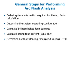
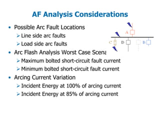
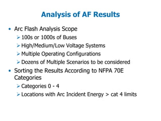
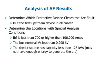
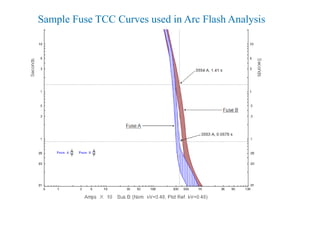
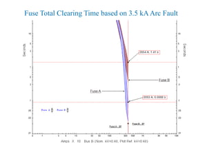
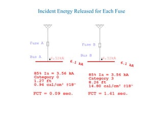
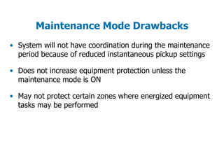
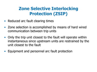
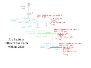
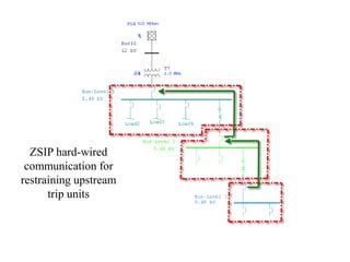
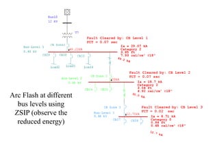
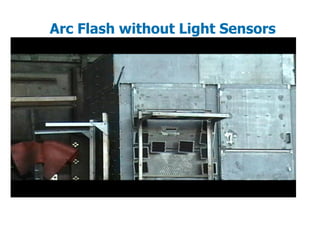
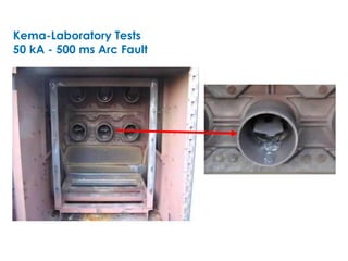
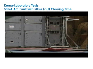
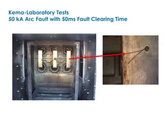
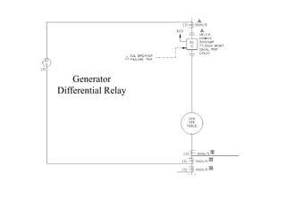
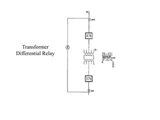
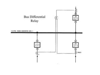
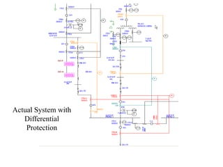
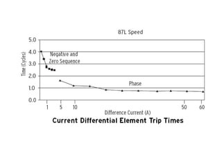
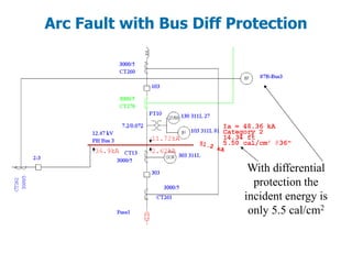
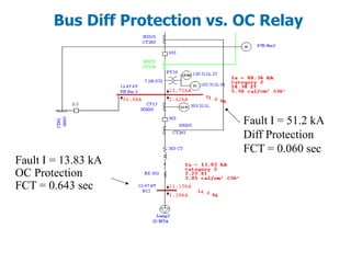
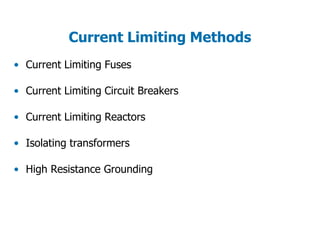
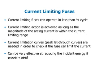
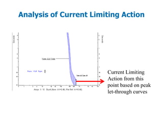
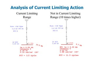
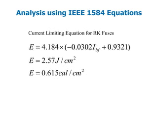
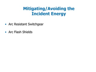
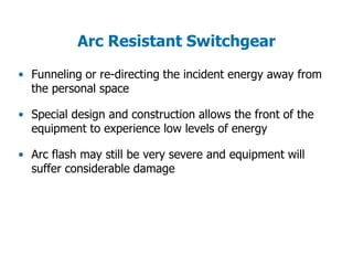
SlideShare a Scribd company logo
Arc Flash Analysis & Mitigation
Methods
By Albert Marroquin
Operation Technology, Inc.
IEEE 1584 2004a “Guide for Performing Arc Flash
Hazard Calculations”
NFPA 70E 2004 “Standard for Electrical Safety
Requirements for Employee Workplaces”
Analysis Methods for Arc Flash Hazards
• AF Concepts and Analysis
• What is new in NFPA 70 2009
• NFPA 70E & IEEE 1584 Methodology – Arc Flash exercise 5
• Arc Flash study case & display options - Arc Flash exercise 1
• AF Analysis for LV - Arc Flash exercise 4
• AF Report Analyzer- Arc Flash exercise 2
• AF differential protection – Arc Flash exercise 6
• AF for 1-Phase applications – Arc Flash exercise 7
• AF Options (preferences) – Arc Flash exercise 3
• Questions and Answers session
AGENDA
General Steps for Performing
Arc Flash Analysis
• Collect system information required for the arc flash
calculation
• Determine the system operating configuration
• Calculate 3-Phase bolted fault currents
• Calculate arcing fault current (IEEE only)
• Determine arc fault clearing time (arc duration) - TCC
• Calculate incident energy
• Determine flash protection boundary
• Determine Hazard/Risk Category based on NFPA 70E
requirements
• Select appropriate protective equipment (PPE Matrix)
General Steps for Performing
Arc Flash Analysis
AF Analysis Considerations
• Possible Arc Fault Locations
Line side arc faults
Load side arc faults
• Arc Flash Analysis Worst Case Scenarios
Maximum bolted short-circuit fault current
Minimum bolted short-circuit fault current
• Arcing Current Variation
Incident Energy at 100% of arcing current
Incident Energy at 85% of arcing current
Analysis of AF Results
• Arc Flash Analysis Scope
100s or 1000s of Buses
High/Medium/Low Voltage Systems
Multiple Operating Configurations
Dozens of Multiple Scenarios to be considered
• Sorting the Results According to NFPA 70E
Categories
Categories 0 - 4
Locations with Arc Incident Energy > cat 4 limits
Analysis of AF Results
• Determine Which Protective Device Clears the Arc Fault
Is it the first upstream device in all cases?
• Determine the Locations with Special Analysis
Conditions
Ibf is less than 700 or higher than 106,000 Amps
The bus nominal kV less than 0.208 kV
The feeder source has capacity less than 125 kVA (may
not have enough energy to generate the arc)
Analysis of AF Results
• Arc Flash Analysis should include:
Labeling of equipment and PPE requirements
Recommendations on mitigation methods
Engineering required to reduce the arc flash hazard
Methods to Mitigate the
Incident Energy
• Methods to Reduce the Fault Clearing Time
Improving coordination settings of OC PDs.
Type 50 protective devices (Instantaneous)
Arc Flash light sensors
Maintenance mode (switch)
Differential protection
Zone selective interlocking protection (ZSIP)
• Methods to Increase the Working Distance
Remote racking of breakers/Remote switching
Use of Hot Sticks
• Methods to Reduce the Short-Circuit Current
Current limiting fuses and circuit breakers
Current limiting reactors, Isolating Transformers
High resistance grounding
• Methods to Reduce the Energy Exposure
Arc resistant switchgear
Arc shields
Infrared scanning, Partial Discharge and or Corona
Cameras
Methods to Mitigate the
Incident Energy
600 Volt Arc in Closed Box Incident energy Exposure @ 18 in.
0
5
10
15
20
0 10 20
Fault clearing time (Cycles)
Calorie/cm^2
NFPA 70E-2000
IEEE 1584-2002
Incident energy exposure at a working distance of 18”
for a 19.5 kA Arc @ 600 Volts (enclosed equipment)
Improving Over-Current Device
Coordination Settings
• Purpose is to isolate the fault with the nearest
upstream over-current protective device
• Arc flash results are extremely dependent on
coordination settings
• Unnecessarily high time dial settings for type 51
over-current devices
• Selection of fuses with faster total clearing time
characteristic curves can reduce the energy significantly
Coordination
t
I
C B A
C
D
D B
A
Arcing current
through A
50/51-1
Incident Energy
released is greater
than 27 cal/cm²
Category 4
Fault Clearing Time
is 37 cycles with
current time dial
settings
Arcing current
through A
50/51-1
Incident Energy
released is less than
8 cal/cm²
Category 2
Fault Clearing Time
= 10 cycles
with lower time dial
settings
Sample Fuse TCC Curves used in Arc Flash Analysis
Fuse Total Clearing Time based on 3.5 kAArc Fault
Incident Energy Released for Each Fuse
Type 50 Protective Device
• Relays with instantaneous settings
• Molded case circuit breakers
• Insulated case breakers
• Power circuit breakers with instantaneous direct acting
trip elements
Type 50 PD Advantages
• Fast acting to reduce the fault clearing time since it can
operate within 3 to 6 cycles
• Commonly available for most MV and LV applications
• Cost effective and do not require special installations
• Already installed in electrical system and may only
require adjustments to reduce the incident energy
Type 50
Protective
Devices
Equipment Specific Incident Energy
Equations for Molded Case CBs
• Equation based calculation of incident energy for molded
case CBs (Eaton Electrical MCCBs)
• Equations were developed based on extensive testing
• Equations typically yield smaller incident energy results
when compared to those obtained with the TCC curve
analysis methods.
• Maintenance and aging of breakers can change the
predicted incident energy release
Example of Eaton Molded Case CB
Equations
• Please note that equations should be used for values
higher than 15*Ir.
Type 50 PD Drawbacks
• To achieve coordination with downstream elements,
upstream source Protective Devices have longer time
delays (do not have instantaneous protection)
• The arcing current magnitude passing through the Type 50
protective device must be higher than the device’s
instantaneous pickup setting
Selective
Coordination
introduces
time delays
Type 50 PD Drawbacks
Maintenance Mode
• Very fast acting trip device reduces the Fault Clearing Time
(FCT)
• Are designed to pickup under very low arcing current
values (instantaneous pickup setting is very low)
• Does not require complicated installation and will
effectively protect locations downstream from the trip unit
with maintenance mode
Maintenance
Mode
Normal
Operating
Mode
Normal Operating
Mode
Normal Operating
Mode
Maintenance Mode
Maintenance Mode
ON
Maintenance Mode Drawbacks
• System will not have coordination during the maintenance
period because of reduced instantaneous pickup settings
• Does not increase equipment protection unless the
maintenance mode is ON
• May not protect certain zones where energized equipment
tasks may be performed
Zone Selective Interlocking
Protection (ZSIP)
• Reduced arc fault clearing times
• Zone selection is accomplished by means of hard wired
communication between trip units
• Only the trip unit closest to the fault will operate within
instantaneous since upstream units are restrained by the
unit closest to the fault
• Equipment and personnel arc fault protection
Normal
Coordination
Settings
Arc Faults at
different bus levels
without ZSIP
ZSIP hard-wired
communication for
restraining upstream
trip units
Arc Flash at different
bus levels using
ZSIP (observe the
reduced energy)
ZSIP Drawbacks
• May take a bit longer to operate than type 50 devices
because of the inherent time delay required for the ZSI
logic operation
• If system is not coordinated, ZSIP does not necessarily
force coordination and other upstream devices may
operate before the device closest to the fault
• Arcing current must still be above short time pickup
Arc Flash Light Sensors
• Detect the light emitted by the arc
• Very fast operation (5 to 10 ms) after the light is detected
• Provide comprehensive zone or individual cubicle arc flash
protection (doors open or closed) when correctly applied
• Light sensor protection can be worn at time of task being
performed for additional safety
Enclosures
Light Sensors
Kema-Laboratory Tests
50 kA - 500 ms Arc Fault Clearing Time
Arc Flash without Light Sensors
Kema-Laboratory Tests
50 kA - 500 ms Arc Fault
Kema-Laboratory Tests
50 kA Arc Fault with 50ms Fault Clearing Time
Kema-Laboratory Tests
50 kA Arc Fault with 50ms Fault Clearing Time
Arc Flash Light Sensor Drawbacks
• Nuisance trips caused by light emitted from sources other
than electrical arcs (can be remedied by using a more
robust approach by combining over-current and light
sensors)
• Positioning of the light sensors poses a possible problem if
they are obstructed or blocked and cannot see the light
emitted by the arc
Light Sensor and
Over-Current Relay
Combination
Differential Protection
• Short Arc Fault Clearing Times
Differential protection can operate (relay plus breaker)
within 4 to 6 cycles
Relay can operate within ½ to 3 cycles
• Maintain coordination between protective devices upstream
and downstream from the Differential Protection Zone
• Differential protection provides continuous equipment arc
flash protection
Types of Differential Relays
• Generator Differential Protection
• Transformer Differential Protection
• Bus Differential Protection
• Line Differential Protection
Generator
Differential Relay
Transformer
Differential Relay
Bus Differential
Relay
Actual System with
Differential
Protection
Arc Fault with Bus Diff Protection
With differential
protection the
incident energy is
only 5.5 cal/cm2
Fault I = 13.83 kA
OC Protection
FCT = 0.643 sec
Fault I = 51.2 kA
Diff Protection
FCT = 0.060 sec
Bus Diff Protection vs. OC Relay
Differential Protection Drawbacks
• Nuisance trips caused by transformer inrush currents which
are seen by relay as internal faults - the magnetizing
current has particularly high second order harmonic content
which can be used to restrain or desensitize the relay
during energizing
• Higher equipment and installation costs - relatively higher
costs when compared to traditional over-current protective
devices
• Limited zone of protection for differential ct nodes
Current Limiting Methods
• Current Limiting Fuses
• Current Limiting Circuit Breakers
• Current Limiting Reactors
• Isolating transformers
• High Resistance Grounding
Current Limiting Fuses
• Current limiting fuses can operate in less than ½ cycle
• Current limiting action is achieved as long as the
magnitude of the arcing current is within the current
limiting range
• Current limitation curves (peak let-through curves) are
needed in order to check if the fuse can limit the current
• Can be very effective at reducing the incident energy if
properly used
Current Limiting ActionCurrent(peakamps)
tm ta
Ip’
Ip
tc
ta = tc – tm
ta = Arcing Time
tm = Melting Time
tc = Clearing Time
Ip = Peak Current
Ip’ = Peak Let-thru Current
Time (cycles)
Current Limiting Action
Analysis of Current Limiting Action
Current Limiting
Action from this
point based on peak
let-through curves
Analysis of Current Limiting Action
Current Limiting
Range
Not in Current Limiting
Range (10 times higher)
Analysis using IEEE 1584 Equations
Current Limiting Equation for RK Fuses
2
2
/615.0
/57.2
)9321.00302.0(184.4
cmcalE
cmJE
IE bf



Current Limiting Fuse Drawbacks
• Current limiting action is achieved as long as the
magnitude of the arcing current is within the current
limiting range
• Can be thermally damaged and have altered characteristics
• Needs spares (which may be expensive) and there is not
indication of the type of fault.
• Energization on pre-existing fault = another blown fuse
Current Limiting Reactors
Isolating Transformers
• Current limiting reactors can help to reduce the available
fault current and thus reduce the available energy
• Isolating transformers help to reduce high kA short-circuit
levels (down to less than 10 kA).
• Isolating transformers add impedance between the main
switchboard and the smaller panels fed from it. The short-
circuit available at the switchboard may be considerably
higher
Increasing the Working Distance
• Hot Sticks
• Remote Racking
• Remote Switching
• Used to insulate the electrician from electric shock and to
increase the distance from arc flash/blast
• Should be inspected prior to each use for signs of cracks or
physical damage which may affect the insulating capability
• Need to wear additional PPE
Using Hot Sticks
Using Hot Sticks
• Are used to increase the personal space between the
potential source of the arc and the electrician
• Can be combined with high strength plastic shields to
reduce the effects of the arc flash/blast
Remote Racking/Remote
Switching
Remote Racking/Remote
Switching
Remote Racking/Remote
Switching
Mitigating/Avoiding the
Incident Energy
• Arc Resistant Switchgear
• Arc Flash Shields
Arc Resistant Switchgear
• Funneling or re-directing the incident energy away from
the personal space
• Special design and construction allows the front of the
equipment to experience low levels of energy
• Arc flash may still be very severe and equipment will
suffer considerable damage
Arc Resistant Switchgear
Infrared Scanning
• Infrared scanning can help detect loose connections by
detecting hot spots and thus avoiding an arc flash
• Infrared scanning only helps to detect equipment failure
which may cause an arc, but it does not reduce the risk of
arc flash incidents caused by human error
Infrared Scanning
Partial Discharge Measurements
• Measures partial discharge activity through analysis of high
frequency activity
• Identifies areas where insulation is breaking down
• Digital Oscilloscope with noise reduction software
• Connects to existing CT’s, PT’s or RTD circuits
• No shutdowns required
Partial Discharge Measurement
Results of Partial Discharges
<<< Corona
Corona (Close up) >>>
Results of Partial Discharges
<<Tracking 4,160 Volt
Surface Discharges >>>
and Void Type Defect
Best Solution to
Mitigate the AF Risk
• De-energize the equipment
The best strategy to protect against arc flash dangers
is to de-energize the equipment before working on it
Acknowledgements
• Eaton Cutler-Hammer
• ETAP Canada Ltd.
• QIP2
• VAMP
• Shaw
Thank You.

More Related Content

What's hot

ETAP - Coordination and protecion
ETAP -  Coordination and protecionETAP -  Coordination and protecion
ETAP - Coordination and protecion
Himmelstern
 
ETAP - Transient stability 2
ETAP - Transient stability 2ETAP - Transient stability 2
ETAP - Transient stability 2
Himmelstern
 
ETAP - device coordination
ETAP - device coordinationETAP - device coordination
ETAP - device coordination
Himmelstern
 
ETAP - 09 motor-acceleration
ETAP - 09 motor-accelerationETAP - 09 motor-acceleration
ETAP - 09 motor-acceleration
Himmelstern
 
Switchgear - complete guide
Switchgear - complete guideSwitchgear - complete guide
Switchgear - complete guide
Slides Hub
 
ETAP Training.pptx
ETAP Training.pptxETAP Training.pptx
ETAP Training.pptx
Hoshangs
 
Generator Protection Relay Setting Calculations
Generator Protection Relay Setting CalculationsGenerator Protection Relay Setting Calculations
Generator Protection Relay Setting Calculations
Power System Operation
 
Generator protection calculations settings
Generator protection calculations settingsGenerator protection calculations settings
Generator protection calculations settings
michaeljmack
 
Principles of Cable Sizing
Principles of Cable SizingPrinciples of Cable Sizing
Principles of Cable Sizing
Leonardo ENERGY
 
ETAP - Coordinación de protecciones y arco eléctrico
ETAP - Coordinación de protecciones y arco eléctricoETAP - Coordinación de protecciones y arco eléctrico
ETAP - Coordinación de protecciones y arco eléctrico
Himmelstern
 
ETAP - Transformer sizing using etap
ETAP - Transformer sizing using etapETAP - Transformer sizing using etap
ETAP - Transformer sizing using etap
Himmelstern
 
Practical handbook-for-relay-protection-engineers
Practical handbook-for-relay-protection-engineersPractical handbook-for-relay-protection-engineers
Practical handbook-for-relay-protection-engineers
SARAVANAN A
 
Lv switchgear &amp; lv cable sizing
Lv switchgear &amp; lv cable sizingLv switchgear &amp; lv cable sizing
Lv switchgear &amp; lv cable sizing
Asif Eqbal
 
Cable sizing part 2
Cable sizing part 2Cable sizing part 2
Cable sizing part 2
Febrian Sasi Kirana
 
Power system protection topic 1
Power system protection topic 1Power system protection topic 1
Power system protection topic 1
Siswoyo Edo
 
3. INTRODUCTION TO PROTECTIVE RELAYING.pptx
3. INTRODUCTION TO PROTECTIVE RELAYING.pptx3. INTRODUCTION TO PROTECTIVE RELAYING.pptx
3. INTRODUCTION TO PROTECTIVE RELAYING.pptx
Muhd Hafizi Idris
 
Transformer differential protection
Transformer differential protection Transformer differential protection
Transformer differential protection
michaeljmack
 
Thyristor switched capacitor PPT
Thyristor switched capacitor PPTThyristor switched capacitor PPT
Thyristor switched capacitor PPT
KLS' S GIT, BELGAUM
 
ETAP - Load flow and panel rev2014-1
ETAP - Load flow and panel   rev2014-1ETAP - Load flow and panel   rev2014-1
ETAP - Load flow and panel rev2014-1
Himmelstern
 
MV Switchgear from IEEE
MV Switchgear from IEEEMV Switchgear from IEEE

What's hot (20)

ETAP - Coordination and protecion
ETAP -  Coordination and protecionETAP -  Coordination and protecion
ETAP - Coordination and protecion
 
ETAP - Transient stability 2
ETAP - Transient stability 2ETAP - Transient stability 2
ETAP - Transient stability 2
 
ETAP - device coordination
ETAP - device coordinationETAP - device coordination
ETAP - device coordination
 
ETAP - 09 motor-acceleration
ETAP - 09 motor-accelerationETAP - 09 motor-acceleration
ETAP - 09 motor-acceleration
 
Switchgear - complete guide
Switchgear - complete guideSwitchgear - complete guide
Switchgear - complete guide
 
ETAP Training.pptx
ETAP Training.pptxETAP Training.pptx
ETAP Training.pptx
 
Generator Protection Relay Setting Calculations
Generator Protection Relay Setting CalculationsGenerator Protection Relay Setting Calculations
Generator Protection Relay Setting Calculations
 
Generator protection calculations settings
Generator protection calculations settingsGenerator protection calculations settings
Generator protection calculations settings
 
Principles of Cable Sizing
Principles of Cable SizingPrinciples of Cable Sizing
Principles of Cable Sizing
 
ETAP - Coordinación de protecciones y arco eléctrico
ETAP - Coordinación de protecciones y arco eléctricoETAP - Coordinación de protecciones y arco eléctrico
ETAP - Coordinación de protecciones y arco eléctrico
 
ETAP - Transformer sizing using etap
ETAP - Transformer sizing using etapETAP - Transformer sizing using etap
ETAP - Transformer sizing using etap
 
Practical handbook-for-relay-protection-engineers
Practical handbook-for-relay-protection-engineersPractical handbook-for-relay-protection-engineers
Practical handbook-for-relay-protection-engineers
 
Lv switchgear &amp; lv cable sizing
Lv switchgear &amp; lv cable sizingLv switchgear &amp; lv cable sizing
Lv switchgear &amp; lv cable sizing
 
Cable sizing part 2
Cable sizing part 2Cable sizing part 2
Cable sizing part 2
 
Power system protection topic 1
Power system protection topic 1Power system protection topic 1
Power system protection topic 1
 
3. INTRODUCTION TO PROTECTIVE RELAYING.pptx
3. INTRODUCTION TO PROTECTIVE RELAYING.pptx3. INTRODUCTION TO PROTECTIVE RELAYING.pptx
3. INTRODUCTION TO PROTECTIVE RELAYING.pptx
 
Transformer differential protection
Transformer differential protection Transformer differential protection
Transformer differential protection
 
Thyristor switched capacitor PPT
Thyristor switched capacitor PPTThyristor switched capacitor PPT
Thyristor switched capacitor PPT
 
ETAP - Load flow and panel rev2014-1
ETAP - Load flow and panel   rev2014-1ETAP - Load flow and panel   rev2014-1
ETAP - Load flow and panel rev2014-1
 
MV Switchgear from IEEE
MV Switchgear from IEEEMV Switchgear from IEEE
MV Switchgear from IEEE
 

Similar to ETAP - Arcflash analysis & mitigation methods

Selective Coodination
Selective CoodinationSelective Coodination
Selective Coodination
michaeljmack
 
Short-Circuit Protective Device Coordination & Arc Flash Analysis
Short-Circuit Protective Device Coordination & Arc Flash AnalysisShort-Circuit Protective Device Coordination & Arc Flash Analysis
Short-Circuit Protective Device Coordination & Arc Flash Analysis
Power System Operation
 
Bil and insulation coordination ppt
Bil and insulation coordination pptBil and insulation coordination ppt
Bil and insulation coordination ppt
BILAL ALAM
 
A Comparison of Contemporary Electrical Distribution Equipment Standards
A Comparison of Contemporary Electrical Distribution Equipment StandardsA Comparison of Contemporary Electrical Distribution Equipment Standards
A Comparison of Contemporary Electrical Distribution Equipment Standards
michaeljmack
 
Time current curves
Time current curvesTime current curves
Time current curves
Rabah Zaimeddine
 
IEEE Blue Book
IEEE Blue BookIEEE Blue Book
IEEE Blue Book
michaeljmack
 
RCBU-2-Arc-Flash-Protection_Key_Considerations_for_Selection
RCBU-2-Arc-Flash-Protection_Key_Considerations_for_SelectionRCBU-2-Arc-Flash-Protection_Key_Considerations_for_Selection
RCBU-2-Arc-Flash-Protection_Key_Considerations_for_SelectionKieron King
 
L.v tech presentation 2
L.v tech presentation 2L.v tech presentation 2
Power_System_Protection Lecture-1.pdf
Power_System_Protection Lecture-1.pdfPower_System_Protection Lecture-1.pdf
Power_System_Protection Lecture-1.pdf
YogeshGairola2
 
Troubleshooting Variable Speed Drives
Troubleshooting Variable Speed DrivesTroubleshooting Variable Speed Drives
Troubleshooting Variable Speed DrivesLiving Online
 
Insulation coordination
Insulation coordinationInsulation coordination
Insulation coordination
sarunkutti
 
Power factor corrector
Power factor correctorPower factor corrector
Power factor corrector
JoeChueng
 
Power Electronics and Switch Mode Power Supply
Power Electronics and Switch Mode Power SupplyPower Electronics and Switch Mode Power Supply
Power Electronics and Switch Mode Power Supply
Living Online
 
Selective Coordination "The Rest of the Story"
Selective Coordination "The Rest of the Story"Selective Coordination "The Rest of the Story"
Selective Coordination "The Rest of the Story"
michaeljmack
 
Ohiri-Principles-and-Philosophy-of-Protective-Relaying.pptx
Ohiri-Principles-and-Philosophy-of-Protective-Relaying.pptxOhiri-Principles-and-Philosophy-of-Protective-Relaying.pptx
Ohiri-Principles-and-Philosophy-of-Protective-Relaying.pptx
Godwin308555
 
Presentation on Dehar power house(DPH), slapper
Presentation on Dehar power house(DPH), slapperPresentation on Dehar power house(DPH), slapper
Presentation on Dehar power house(DPH), slapper
Jyoti Rawat
 
lowpower consumption and details of dfferent power pdf
lowpower consumption and details of dfferent power pdflowpower consumption and details of dfferent power pdf
lowpower consumption and details of dfferent power pdf
ManiBharathNuti1
 
Challenges of Short Circuit Protection for Wide Band Gap Power Semiconductor ...
Challenges of Short Circuit Protection for Wide Band Gap Power Semiconductor ...Challenges of Short Circuit Protection for Wide Band Gap Power Semiconductor ...
Challenges of Short Circuit Protection for Wide Band Gap Power Semiconductor ...
ssuserd8745a
 
Switchgear presentation
Switchgear presentationSwitchgear presentation
Switchgear presentation
Ahmed Saada, (PRMG)
 
Circuit Breakers Interrupting Capacity and Short-Time Current Rating
Circuit Breakers Interrupting Capacity and Short-Time Current Rating Circuit Breakers Interrupting Capacity and Short-Time Current Rating
Circuit Breakers Interrupting Capacity and Short-Time Current Rating
michaeljmack
 

Similar to ETAP - Arcflash analysis & mitigation methods (20)

Selective Coodination
Selective CoodinationSelective Coodination
Selective Coodination
 
Short-Circuit Protective Device Coordination & Arc Flash Analysis
Short-Circuit Protective Device Coordination & Arc Flash AnalysisShort-Circuit Protective Device Coordination & Arc Flash Analysis
Short-Circuit Protective Device Coordination & Arc Flash Analysis
 
Bil and insulation coordination ppt
Bil and insulation coordination pptBil and insulation coordination ppt
Bil and insulation coordination ppt
 
A Comparison of Contemporary Electrical Distribution Equipment Standards
A Comparison of Contemporary Electrical Distribution Equipment StandardsA Comparison of Contemporary Electrical Distribution Equipment Standards
A Comparison of Contemporary Electrical Distribution Equipment Standards
 
Time current curves
Time current curvesTime current curves
Time current curves
 
IEEE Blue Book
IEEE Blue BookIEEE Blue Book
IEEE Blue Book
 
RCBU-2-Arc-Flash-Protection_Key_Considerations_for_Selection
RCBU-2-Arc-Flash-Protection_Key_Considerations_for_SelectionRCBU-2-Arc-Flash-Protection_Key_Considerations_for_Selection
RCBU-2-Arc-Flash-Protection_Key_Considerations_for_Selection
 
L.v tech presentation 2
L.v tech presentation 2L.v tech presentation 2
L.v tech presentation 2
 
Power_System_Protection Lecture-1.pdf
Power_System_Protection Lecture-1.pdfPower_System_Protection Lecture-1.pdf
Power_System_Protection Lecture-1.pdf
 
Troubleshooting Variable Speed Drives
Troubleshooting Variable Speed DrivesTroubleshooting Variable Speed Drives
Troubleshooting Variable Speed Drives
 
Insulation coordination
Insulation coordinationInsulation coordination
Insulation coordination
 
Power factor corrector
Power factor correctorPower factor corrector
Power factor corrector
 
Power Electronics and Switch Mode Power Supply
Power Electronics and Switch Mode Power SupplyPower Electronics and Switch Mode Power Supply
Power Electronics and Switch Mode Power Supply
 
Selective Coordination "The Rest of the Story"
Selective Coordination "The Rest of the Story"Selective Coordination "The Rest of the Story"
Selective Coordination "The Rest of the Story"
 
Ohiri-Principles-and-Philosophy-of-Protective-Relaying.pptx
Ohiri-Principles-and-Philosophy-of-Protective-Relaying.pptxOhiri-Principles-and-Philosophy-of-Protective-Relaying.pptx
Ohiri-Principles-and-Philosophy-of-Protective-Relaying.pptx
 
Presentation on Dehar power house(DPH), slapper
Presentation on Dehar power house(DPH), slapperPresentation on Dehar power house(DPH), slapper
Presentation on Dehar power house(DPH), slapper
 
lowpower consumption and details of dfferent power pdf
lowpower consumption and details of dfferent power pdflowpower consumption and details of dfferent power pdf
lowpower consumption and details of dfferent power pdf
 
Challenges of Short Circuit Protection for Wide Band Gap Power Semiconductor ...
Challenges of Short Circuit Protection for Wide Band Gap Power Semiconductor ...Challenges of Short Circuit Protection for Wide Band Gap Power Semiconductor ...
Challenges of Short Circuit Protection for Wide Band Gap Power Semiconductor ...
 
Switchgear presentation
Switchgear presentationSwitchgear presentation
Switchgear presentation
 
Circuit Breakers Interrupting Capacity and Short-Time Current Rating
Circuit Breakers Interrupting Capacity and Short-Time Current Rating Circuit Breakers Interrupting Capacity and Short-Time Current Rating
Circuit Breakers Interrupting Capacity and Short-Time Current Rating
 

Recently uploaded

Student information management system project report ii.pdf
Student information management system project report ii.pdfStudent information management system project report ii.pdf
Student information management system project report ii.pdf
Kamal Acharya
 
在线办理(ANU毕业证书)澳洲国立大学毕业证录取通知书一模一样
在线办理(ANU毕业证书)澳洲国立大学毕业证录取通知书一模一样在线办理(ANU毕业证书)澳洲国立大学毕业证录取通知书一模一样
在线办理(ANU毕业证书)澳洲国立大学毕业证录取通知书一模一样
obonagu
 
Architectural Portfolio Sean Lockwood
Architectural Portfolio Sean LockwoodArchitectural Portfolio Sean Lockwood
Architectural Portfolio Sean Lockwood
seandesed
 
ML for identifying fraud using open blockchain data.pptx
ML for identifying fraud using open blockchain data.pptxML for identifying fraud using open blockchain data.pptx
ML for identifying fraud using open blockchain data.pptx
Vijay Dialani, PhD
 
WATER CRISIS and its solutions-pptx 1234
WATER CRISIS and its solutions-pptx 1234WATER CRISIS and its solutions-pptx 1234
WATER CRISIS and its solutions-pptx 1234
AafreenAbuthahir2
 
Gen AI Study Jams _ For the GDSC Leads in India.pdf
Gen AI Study Jams _ For the GDSC Leads in India.pdfGen AI Study Jams _ For the GDSC Leads in India.pdf
Gen AI Study Jams _ For the GDSC Leads in India.pdf
gdsczhcet
 
AP LAB PPT.pdf ap lab ppt no title specific
AP LAB PPT.pdf ap lab ppt no title specificAP LAB PPT.pdf ap lab ppt no title specific
AP LAB PPT.pdf ap lab ppt no title specific
BrazilAccount1
 
Industrial Training at Shahjalal Fertilizer Company Limited (SFCL)
Industrial Training at Shahjalal Fertilizer Company Limited (SFCL)Industrial Training at Shahjalal Fertilizer Company Limited (SFCL)
Industrial Training at Shahjalal Fertilizer Company Limited (SFCL)
MdTanvirMahtab2
 
一比一原版(SFU毕业证)西蒙菲莎大学毕业证成绩单如何办理
一比一原版(SFU毕业证)西蒙菲莎大学毕业证成绩单如何办理一比一原版(SFU毕业证)西蒙菲莎大学毕业证成绩单如何办理
一比一原版(SFU毕业证)西蒙菲莎大学毕业证成绩单如何办理
bakpo1
 
RAT: Retrieval Augmented Thoughts Elicit Context-Aware Reasoning in Long-Hori...
RAT: Retrieval Augmented Thoughts Elicit Context-Aware Reasoning in Long-Hori...RAT: Retrieval Augmented Thoughts Elicit Context-Aware Reasoning in Long-Hori...
RAT: Retrieval Augmented Thoughts Elicit Context-Aware Reasoning in Long-Hori...
thanhdowork
 
Final project report on grocery store management system..pdf
Final project report on grocery store management system..pdfFinal project report on grocery store management system..pdf
Final project report on grocery store management system..pdf
Kamal Acharya
 
Governing Equations for Fundamental Aerodynamics_Anderson2010.pdf
Governing Equations for Fundamental Aerodynamics_Anderson2010.pdfGoverning Equations for Fundamental Aerodynamics_Anderson2010.pdf
Governing Equations for Fundamental Aerodynamics_Anderson2010.pdf
WENKENLI1
 
NO1 Uk best vashikaran specialist in delhi vashikaran baba near me online vas...
NO1 Uk best vashikaran specialist in delhi vashikaran baba near me online vas...NO1 Uk best vashikaran specialist in delhi vashikaran baba near me online vas...
NO1 Uk best vashikaran specialist in delhi vashikaran baba near me online vas...
Amil Baba Dawood bangali
 
MCQ Soil mechanics questions (Soil shear strength).pdf
MCQ Soil mechanics questions (Soil shear strength).pdfMCQ Soil mechanics questions (Soil shear strength).pdf
MCQ Soil mechanics questions (Soil shear strength).pdf
Osamah Alsalih
 
weather web application report.pdf
weather web application report.pdfweather web application report.pdf
weather web application report.pdf
Pratik Pawar
 
CME397 Surface Engineering- Professional Elective
CME397 Surface Engineering- Professional ElectiveCME397 Surface Engineering- Professional Elective
CME397 Surface Engineering- Professional Elective
karthi keyan
 
Standard Reomte Control Interface - Neometrix
Standard Reomte Control Interface - NeometrixStandard Reomte Control Interface - Neometrix
Standard Reomte Control Interface - Neometrix
Neometrix_Engineering_Pvt_Ltd
 
Runway Orientation Based on the Wind Rose Diagram.pptx
Runway Orientation Based on the Wind Rose Diagram.pptxRunway Orientation Based on the Wind Rose Diagram.pptx
Runway Orientation Based on the Wind Rose Diagram.pptx
SupreethSP4
 
Design and Analysis of Algorithms-DP,Backtracking,Graphs,B&B
Design and Analysis of Algorithms-DP,Backtracking,Graphs,B&BDesign and Analysis of Algorithms-DP,Backtracking,Graphs,B&B
Design and Analysis of Algorithms-DP,Backtracking,Graphs,B&B
Sreedhar Chowdam
 
Pile Foundation by Venkatesh Taduvai (Sub Geotechnical Engineering II)-conver...
Pile Foundation by Venkatesh Taduvai (Sub Geotechnical Engineering II)-conver...Pile Foundation by Venkatesh Taduvai (Sub Geotechnical Engineering II)-conver...
Pile Foundation by Venkatesh Taduvai (Sub Geotechnical Engineering II)-conver...
AJAYKUMARPUND1
 

Recently uploaded (20)

Student information management system project report ii.pdf
Student information management system project report ii.pdfStudent information management system project report ii.pdf
Student information management system project report ii.pdf
 
在线办理(ANU毕业证书)澳洲国立大学毕业证录取通知书一模一样
在线办理(ANU毕业证书)澳洲国立大学毕业证录取通知书一模一样在线办理(ANU毕业证书)澳洲国立大学毕业证录取通知书一模一样
在线办理(ANU毕业证书)澳洲国立大学毕业证录取通知书一模一样
 
Architectural Portfolio Sean Lockwood
Architectural Portfolio Sean LockwoodArchitectural Portfolio Sean Lockwood
Architectural Portfolio Sean Lockwood
 
ML for identifying fraud using open blockchain data.pptx
ML for identifying fraud using open blockchain data.pptxML for identifying fraud using open blockchain data.pptx
ML for identifying fraud using open blockchain data.pptx
 
WATER CRISIS and its solutions-pptx 1234
WATER CRISIS and its solutions-pptx 1234WATER CRISIS and its solutions-pptx 1234
WATER CRISIS and its solutions-pptx 1234
 
Gen AI Study Jams _ For the GDSC Leads in India.pdf
Gen AI Study Jams _ For the GDSC Leads in India.pdfGen AI Study Jams _ For the GDSC Leads in India.pdf
Gen AI Study Jams _ For the GDSC Leads in India.pdf
 
AP LAB PPT.pdf ap lab ppt no title specific
AP LAB PPT.pdf ap lab ppt no title specificAP LAB PPT.pdf ap lab ppt no title specific
AP LAB PPT.pdf ap lab ppt no title specific
 
Industrial Training at Shahjalal Fertilizer Company Limited (SFCL)
Industrial Training at Shahjalal Fertilizer Company Limited (SFCL)Industrial Training at Shahjalal Fertilizer Company Limited (SFCL)
Industrial Training at Shahjalal Fertilizer Company Limited (SFCL)
 
一比一原版(SFU毕业证)西蒙菲莎大学毕业证成绩单如何办理
一比一原版(SFU毕业证)西蒙菲莎大学毕业证成绩单如何办理一比一原版(SFU毕业证)西蒙菲莎大学毕业证成绩单如何办理
一比一原版(SFU毕业证)西蒙菲莎大学毕业证成绩单如何办理
 
RAT: Retrieval Augmented Thoughts Elicit Context-Aware Reasoning in Long-Hori...
RAT: Retrieval Augmented Thoughts Elicit Context-Aware Reasoning in Long-Hori...RAT: Retrieval Augmented Thoughts Elicit Context-Aware Reasoning in Long-Hori...
RAT: Retrieval Augmented Thoughts Elicit Context-Aware Reasoning in Long-Hori...
 
Final project report on grocery store management system..pdf
Final project report on grocery store management system..pdfFinal project report on grocery store management system..pdf
Final project report on grocery store management system..pdf
 
Governing Equations for Fundamental Aerodynamics_Anderson2010.pdf
Governing Equations for Fundamental Aerodynamics_Anderson2010.pdfGoverning Equations for Fundamental Aerodynamics_Anderson2010.pdf
Governing Equations for Fundamental Aerodynamics_Anderson2010.pdf
 
NO1 Uk best vashikaran specialist in delhi vashikaran baba near me online vas...
NO1 Uk best vashikaran specialist in delhi vashikaran baba near me online vas...NO1 Uk best vashikaran specialist in delhi vashikaran baba near me online vas...
NO1 Uk best vashikaran specialist in delhi vashikaran baba near me online vas...
 
MCQ Soil mechanics questions (Soil shear strength).pdf
MCQ Soil mechanics questions (Soil shear strength).pdfMCQ Soil mechanics questions (Soil shear strength).pdf
MCQ Soil mechanics questions (Soil shear strength).pdf
 
weather web application report.pdf
weather web application report.pdfweather web application report.pdf
weather web application report.pdf
 
CME397 Surface Engineering- Professional Elective
CME397 Surface Engineering- Professional ElectiveCME397 Surface Engineering- Professional Elective
CME397 Surface Engineering- Professional Elective
 
Standard Reomte Control Interface - Neometrix
Standard Reomte Control Interface - NeometrixStandard Reomte Control Interface - Neometrix
Standard Reomte Control Interface - Neometrix
 
Runway Orientation Based on the Wind Rose Diagram.pptx
Runway Orientation Based on the Wind Rose Diagram.pptxRunway Orientation Based on the Wind Rose Diagram.pptx
Runway Orientation Based on the Wind Rose Diagram.pptx
 
Design and Analysis of Algorithms-DP,Backtracking,Graphs,B&B
Design and Analysis of Algorithms-DP,Backtracking,Graphs,B&BDesign and Analysis of Algorithms-DP,Backtracking,Graphs,B&B
Design and Analysis of Algorithms-DP,Backtracking,Graphs,B&B
 
Pile Foundation by Venkatesh Taduvai (Sub Geotechnical Engineering II)-conver...
Pile Foundation by Venkatesh Taduvai (Sub Geotechnical Engineering II)-conver...Pile Foundation by Venkatesh Taduvai (Sub Geotechnical Engineering II)-conver...
Pile Foundation by Venkatesh Taduvai (Sub Geotechnical Engineering II)-conver...
 

ETAP - Arcflash analysis & mitigation methods

  • 1. Arc Flash Analysis & Mitigation Methods By Albert Marroquin Operation Technology, Inc.
  • 2. IEEE 1584 2004a “Guide for Performing Arc Flash Hazard Calculations” NFPA 70E 2004 “Standard for Electrical Safety Requirements for Employee Workplaces” Analysis Methods for Arc Flash Hazards
  • 3. • AF Concepts and Analysis • What is new in NFPA 70 2009 • NFPA 70E & IEEE 1584 Methodology – Arc Flash exercise 5 • Arc Flash study case & display options - Arc Flash exercise 1 • AF Analysis for LV - Arc Flash exercise 4 • AF Report Analyzer- Arc Flash exercise 2 • AF differential protection – Arc Flash exercise 6 • AF for 1-Phase applications – Arc Flash exercise 7 • AF Options (preferences) – Arc Flash exercise 3 • Questions and Answers session AGENDA
  • 4. General Steps for Performing Arc Flash Analysis • Collect system information required for the arc flash calculation • Determine the system operating configuration • Calculate 3-Phase bolted fault currents • Calculate arcing fault current (IEEE only) • Determine arc fault clearing time (arc duration) - TCC
  • 5. • Calculate incident energy • Determine flash protection boundary • Determine Hazard/Risk Category based on NFPA 70E requirements • Select appropriate protective equipment (PPE Matrix) General Steps for Performing Arc Flash Analysis
  • 6. AF Analysis Considerations • Possible Arc Fault Locations Line side arc faults Load side arc faults • Arc Flash Analysis Worst Case Scenarios Maximum bolted short-circuit fault current Minimum bolted short-circuit fault current • Arcing Current Variation Incident Energy at 100% of arcing current Incident Energy at 85% of arcing current
  • 7. Analysis of AF Results • Arc Flash Analysis Scope 100s or 1000s of Buses High/Medium/Low Voltage Systems Multiple Operating Configurations Dozens of Multiple Scenarios to be considered • Sorting the Results According to NFPA 70E Categories Categories 0 - 4 Locations with Arc Incident Energy > cat 4 limits
  • 8. Analysis of AF Results • Determine Which Protective Device Clears the Arc Fault Is it the first upstream device in all cases? • Determine the Locations with Special Analysis Conditions Ibf is less than 700 or higher than 106,000 Amps The bus nominal kV less than 0.208 kV The feeder source has capacity less than 125 kVA (may not have enough energy to generate the arc)
  • 9. Analysis of AF Results • Arc Flash Analysis should include: Labeling of equipment and PPE requirements Recommendations on mitigation methods Engineering required to reduce the arc flash hazard
  • 10. Methods to Mitigate the Incident Energy • Methods to Reduce the Fault Clearing Time Improving coordination settings of OC PDs. Type 50 protective devices (Instantaneous) Arc Flash light sensors Maintenance mode (switch) Differential protection Zone selective interlocking protection (ZSIP) • Methods to Increase the Working Distance Remote racking of breakers/Remote switching Use of Hot Sticks
  • 11. • Methods to Reduce the Short-Circuit Current Current limiting fuses and circuit breakers Current limiting reactors, Isolating Transformers High resistance grounding • Methods to Reduce the Energy Exposure Arc resistant switchgear Arc shields Infrared scanning, Partial Discharge and or Corona Cameras Methods to Mitigate the Incident Energy
  • 12. 600 Volt Arc in Closed Box Incident energy Exposure @ 18 in. 0 5 10 15 20 0 10 20 Fault clearing time (Cycles) Calorie/cm^2 NFPA 70E-2000 IEEE 1584-2002 Incident energy exposure at a working distance of 18” for a 19.5 kA Arc @ 600 Volts (enclosed equipment)
  • 13. Improving Over-Current Device Coordination Settings • Purpose is to isolate the fault with the nearest upstream over-current protective device • Arc flash results are extremely dependent on coordination settings • Unnecessarily high time dial settings for type 51 over-current devices • Selection of fuses with faster total clearing time characteristic curves can reduce the energy significantly
  • 15. Arcing current through A 50/51-1 Incident Energy released is greater than 27 cal/cm² Category 4 Fault Clearing Time is 37 cycles with current time dial settings
  • 16. Arcing current through A 50/51-1 Incident Energy released is less than 8 cal/cm² Category 2 Fault Clearing Time = 10 cycles with lower time dial settings
  • 17. Sample Fuse TCC Curves used in Arc Flash Analysis
  • 18. Fuse Total Clearing Time based on 3.5 kAArc Fault
  • 19. Incident Energy Released for Each Fuse
  • 20. Type 50 Protective Device • Relays with instantaneous settings • Molded case circuit breakers • Insulated case breakers • Power circuit breakers with instantaneous direct acting trip elements
  • 21. Type 50 PD Advantages • Fast acting to reduce the fault clearing time since it can operate within 3 to 6 cycles • Commonly available for most MV and LV applications • Cost effective and do not require special installations • Already installed in electrical system and may only require adjustments to reduce the incident energy
  • 23. Equipment Specific Incident Energy Equations for Molded Case CBs • Equation based calculation of incident energy for molded case CBs (Eaton Electrical MCCBs) • Equations were developed based on extensive testing • Equations typically yield smaller incident energy results when compared to those obtained with the TCC curve analysis methods. • Maintenance and aging of breakers can change the predicted incident energy release
  • 24. Example of Eaton Molded Case CB Equations • Please note that equations should be used for values higher than 15*Ir.
  • 25. Type 50 PD Drawbacks • To achieve coordination with downstream elements, upstream source Protective Devices have longer time delays (do not have instantaneous protection) • The arcing current magnitude passing through the Type 50 protective device must be higher than the device’s instantaneous pickup setting
  • 27. Maintenance Mode • Very fast acting trip device reduces the Fault Clearing Time (FCT) • Are designed to pickup under very low arcing current values (instantaneous pickup setting is very low) • Does not require complicated installation and will effectively protect locations downstream from the trip unit with maintenance mode
  • 28.
  • 34. Maintenance Mode Drawbacks • System will not have coordination during the maintenance period because of reduced instantaneous pickup settings • Does not increase equipment protection unless the maintenance mode is ON • May not protect certain zones where energized equipment tasks may be performed
  • 35. Zone Selective Interlocking Protection (ZSIP) • Reduced arc fault clearing times • Zone selection is accomplished by means of hard wired communication between trip units • Only the trip unit closest to the fault will operate within instantaneous since upstream units are restrained by the unit closest to the fault • Equipment and personnel arc fault protection
  • 37. Arc Faults at different bus levels without ZSIP
  • 39. Arc Flash at different bus levels using ZSIP (observe the reduced energy)
  • 40. ZSIP Drawbacks • May take a bit longer to operate than type 50 devices because of the inherent time delay required for the ZSI logic operation • If system is not coordinated, ZSIP does not necessarily force coordination and other upstream devices may operate before the device closest to the fault • Arcing current must still be above short time pickup
  • 41. Arc Flash Light Sensors • Detect the light emitted by the arc • Very fast operation (5 to 10 ms) after the light is detected • Provide comprehensive zone or individual cubicle arc flash protection (doors open or closed) when correctly applied • Light sensor protection can be worn at time of task being performed for additional safety
  • 44. Kema-Laboratory Tests 50 kA - 500 ms Arc Fault Clearing Time
  • 45. Arc Flash without Light Sensors
  • 46. Kema-Laboratory Tests 50 kA - 500 ms Arc Fault
  • 47. Kema-Laboratory Tests 50 kA Arc Fault with 50ms Fault Clearing Time
  • 48. Kema-Laboratory Tests 50 kA Arc Fault with 50ms Fault Clearing Time
  • 49. Arc Flash Light Sensor Drawbacks • Nuisance trips caused by light emitted from sources other than electrical arcs (can be remedied by using a more robust approach by combining over-current and light sensors) • Positioning of the light sensors poses a possible problem if they are obstructed or blocked and cannot see the light emitted by the arc
  • 50. Light Sensor and Over-Current Relay Combination
  • 51. Differential Protection • Short Arc Fault Clearing Times Differential protection can operate (relay plus breaker) within 4 to 6 cycles Relay can operate within ½ to 3 cycles • Maintain coordination between protective devices upstream and downstream from the Differential Protection Zone • Differential protection provides continuous equipment arc flash protection
  • 52. Types of Differential Relays • Generator Differential Protection • Transformer Differential Protection • Bus Differential Protection • Line Differential Protection
  • 57.
  • 58. Arc Fault with Bus Diff Protection With differential protection the incident energy is only 5.5 cal/cm2
  • 59. Fault I = 13.83 kA OC Protection FCT = 0.643 sec Fault I = 51.2 kA Diff Protection FCT = 0.060 sec Bus Diff Protection vs. OC Relay
  • 60. Differential Protection Drawbacks • Nuisance trips caused by transformer inrush currents which are seen by relay as internal faults - the magnetizing current has particularly high second order harmonic content which can be used to restrain or desensitize the relay during energizing • Higher equipment and installation costs - relatively higher costs when compared to traditional over-current protective devices • Limited zone of protection for differential ct nodes
  • 61. Current Limiting Methods • Current Limiting Fuses • Current Limiting Circuit Breakers • Current Limiting Reactors • Isolating transformers • High Resistance Grounding
  • 62. Current Limiting Fuses • Current limiting fuses can operate in less than ½ cycle • Current limiting action is achieved as long as the magnitude of the arcing current is within the current limiting range • Current limitation curves (peak let-through curves) are needed in order to check if the fuse can limit the current • Can be very effective at reducing the incident energy if properly used
  • 63. Current Limiting ActionCurrent(peakamps) tm ta Ip’ Ip tc ta = tc – tm ta = Arcing Time tm = Melting Time tc = Clearing Time Ip = Peak Current Ip’ = Peak Let-thru Current Time (cycles)
  • 65. Analysis of Current Limiting Action Current Limiting Action from this point based on peak let-through curves
  • 66. Analysis of Current Limiting Action Current Limiting Range Not in Current Limiting Range (10 times higher)
  • 67. Analysis using IEEE 1584 Equations Current Limiting Equation for RK Fuses 2 2 /615.0 /57.2 )9321.00302.0(184.4 cmcalE cmJE IE bf   
  • 68. Current Limiting Fuse Drawbacks • Current limiting action is achieved as long as the magnitude of the arcing current is within the current limiting range • Can be thermally damaged and have altered characteristics • Needs spares (which may be expensive) and there is not indication of the type of fault. • Energization on pre-existing fault = another blown fuse
  • 69. Current Limiting Reactors Isolating Transformers • Current limiting reactors can help to reduce the available fault current and thus reduce the available energy • Isolating transformers help to reduce high kA short-circuit levels (down to less than 10 kA). • Isolating transformers add impedance between the main switchboard and the smaller panels fed from it. The short- circuit available at the switchboard may be considerably higher
  • 70. Increasing the Working Distance • Hot Sticks • Remote Racking • Remote Switching
  • 71. • Used to insulate the electrician from electric shock and to increase the distance from arc flash/blast • Should be inspected prior to each use for signs of cracks or physical damage which may affect the insulating capability • Need to wear additional PPE Using Hot Sticks
  • 73. • Are used to increase the personal space between the potential source of the arc and the electrician • Can be combined with high strength plastic shields to reduce the effects of the arc flash/blast Remote Racking/Remote Switching
  • 76. Mitigating/Avoiding the Incident Energy • Arc Resistant Switchgear • Arc Flash Shields
  • 77. Arc Resistant Switchgear • Funneling or re-directing the incident energy away from the personal space • Special design and construction allows the front of the equipment to experience low levels of energy • Arc flash may still be very severe and equipment will suffer considerable damage
  • 78.
  • 80. Infrared Scanning • Infrared scanning can help detect loose connections by detecting hot spots and thus avoiding an arc flash • Infrared scanning only helps to detect equipment failure which may cause an arc, but it does not reduce the risk of arc flash incidents caused by human error
  • 82. Partial Discharge Measurements • Measures partial discharge activity through analysis of high frequency activity • Identifies areas where insulation is breaking down • Digital Oscilloscope with noise reduction software • Connects to existing CT’s, PT’s or RTD circuits • No shutdowns required
  • 84.
  • 85. Results of Partial Discharges <<< Corona Corona (Close up) >>>
  • 86. Results of Partial Discharges <<Tracking 4,160 Volt Surface Discharges >>> and Void Type Defect
  • 87. Best Solution to Mitigate the AF Risk • De-energize the equipment The best strategy to protect against arc flash dangers is to de-energize the equipment before working on it
  • 88. Acknowledgements • Eaton Cutler-Hammer • ETAP Canada Ltd. • QIP2 • VAMP • Shaw