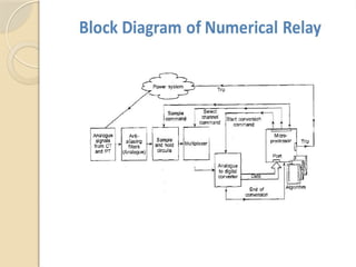
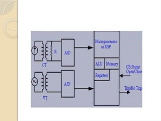
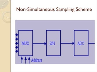
Numerical Relay
Need for protection
 A power system is not only capable to meet the
present load but also has the flexibility to meet
the future demands
 A power system is designed to generate electric
power in sufficient quantity, to meet the present
and estimated future demands of the users in a
particular area, to transmit it to the areas
where it will be used and then distribute it
within that area, on a continuous basis.
 To ensure the maximum return on the
large investment in the equipment, which
goes to make up the power system and
to keep the users satisfied with reliable
service, the whole system must be kept in
operation continuously without major
breakdowns
 Special equipment is normally installed to
detect such kind of failures (also called
‘faults’) that can possibly happen in
various sections of a system, and to
isolate faulty sections so that the
interruption is limited to a localized area
in the total system covering various area
 Hence, use of protective apparatus is very
necessary in the electrical systems, which are
expected to generate, transmit and distribute
power with least interruptions and restoration
time
 It can be well recognized that use of protective
equipment are very vital to minimize the effects
of faults, which otherwise can kill the whole
system
Basic Requirements for Protection
 A protection apparatus has three main
functions/duties:
◦ 1. Safeguard the entire system to maintain
continuity of supply
◦ 2. Minimize damage and repair costs where it
senses fault
◦ 3. Ensure safety of personnel.
Basic components of protection
 Protection of any distribution system is a function of
many elements and this manual gives a brief outline of
various components that go in protecting a system
 Following are the main components of protection;
 Fuse is the self-destructing one, which carries the
currents in a power circuit continuously and sacrifices
itself by blowing under abnormal conditions
 These are normally independent or stand-alone protective
components in an electrical system unlike a circuit
breaker, which necessarily requires the support of
external components
 These requirements are necessary, firstly for early detection and
localization of faults, and secondly for prompt removal of faulty
equipment from service
 In order to carry out the above duties, protection must have the
following qualities:
 • Selectivity:To detect and isolate the faulty item only.
 • Stability: To leave all healthy circuits intact to ensure
continuity or supply.
 • Sensitivity: To detect even the smallest fault, current or
system abnormalities and operate correctly at its setting before the
fault causes irreparable damage.
 • Speed:To operate speedily when it is called upon to do
so, thereby minimizing damage to the surroundings and ensuring
safety to personnel
 Accurate protection cannot be achieved
without properly measuring the normal and
abnormal conditions of a system
 In electrical systems, voltage and current
measurements give feedback on whether a
system is healthy or not
 Voltage transformers and current transformers
measure these basic parameters and are capable
of providing accurate measurement during fault
conditions without failure
 The measured values are converted into analog and/or
digital signals and are made to operate the relays, which
in turn isolate the circuits by opening the faulty circuits.
In most of the cases, the relays provide two functions
viz., alarm and trip, once the abnormality is noticed
 The relays in old days had very limited functions and
were quite bulky
 However, with advancement in digital technology and
use of microprocessors, relays monitor various
parameters, which give complete history of a system
during both pre-fault and post-fault conditions
Faults Types
There are two main types of faults-
 Symmetrical Faults
 Unsymmetrical Faults
Symmetrical or Balance Fault
 A balance three phase fault (L-L-L Fault) is
called as symmetrical fault. In this type of fault,
all the three phases are short circuited. Some
times all the three phases are short circuited to
the ground and in other cases all the three
phases are short circuited without involvement
of ground.The three phase fault is considered as
standard fault for determining fault level of
system.
Unsymmetrical or Unbalance Fault
 Single line to ground short circuit, double
line to ground short circuit, line to line
short circuit, single phase open circuit and
two phase open circuit are unsymmetrical
faults.
Single Line to Ground Fault (L-G Fault)
 When short circuit between any one of
the phase conductor and ground occurs
then this type of fault is called as single
line to ground fault.
Double Line to Ground Fault (L-L-G
Fault)
 When short circuit between any two
phase conductors and ground occurs
then this type of fault is called as double
line to ground fault.
Line to Line Fault (L-L Fault)
 When short circuit between any two
phase conductors occurs then this type
of fault is called as line to line fault.
Open Circuit Phases
 This type of fault is occurred when there
is break in conductor path.This type of
fault caused by breaking of one or more
phase conductors or cable joint or joints
on the overhead line fails. Such faults
occurred when isolators or circuit
breaker are open but fail to close for one
or more phase conductors.
01/17/2025
Winding Faults
 Above mentioned fault also occur on the
alternators, motors and transformers
windings.Also, short circuits of turns
which occur on winding of machine.
01/17/2025
Simultaneous Faults
 Two or more types of faults mentioned above
occurred on the system at same time, then this
type of fault is called simultaneous or multiple
faults. In this type of fault, same or different
types of faults occurred at same or different
locations of the system. For example, single line
to ground fault occur between one conductor
and ground. Breaking of other phase conductor
is second fault. Both faults occur at same time
and same location.
01/17/2025
Series Faults
 Series faults represent open conductor and occur when
unbalanced series impedance conditions of the lines are
present. Consider these examples of series fault are
when the system holds one or two broken lines, or
impedance inserted in one or two lines. In the real
world a series faults takes place, for example, when
circuit breakers controls the lines and do not open all
three phases, in this case, one or two phases of the line
may be open while the others is closed . In series faults
voltage and frequency are increase and current
decreases in the faulted phase.
01/17/2025
Shunt Faults
 The shunt faults are the most familiar
type of fault happening in the power
system network.They involve power
conductors or conductor-to-ground or
short circuits between conductors.
01/17/2025
Causes of Faults
Faults on distribution and transmission lines are due to
overvoltage caused by lightning or switching surges.
Overvoltages due to switching surges or lightning surges
cause flashover on insulator’s surface. It causes a short circuit
between phases.
Faults are caused by broken conductors falling on the ground.
Failure of joints on cables or overhead lines are also causes a
short circuit.
Faults on overhead lines are also caused by aircraft, snakes,
ice and snow loading, storms, earthquakes, creepers.
01/17/2025
Faults in cables, generators and transformers are due to
failure of solid insulation caused by aging, moisture, heat,
overvoltage, mechanical damage, accidental contact with
the ground.
Faults are also caused by flashover due to
overvoltage.Poor quality of power system equipments,
improper maintenance of equipments and errors in
the power system design causes a fault.
Defect in protective devices like circuit breakers and
relays, error in switching operation of circuit breaker,
errors in it’s testing and maintenance causes a fault.
01/17/2025
Faults on power system are caused by insulation failure
of conductor or failure of conducting path.
Failure of insulation of conductors causes short circuit
between conductors.This type of short circuits is very
harmful as it damage to power system equipments.
Faults are also caused by tree branches falling down on
overhead conducting lines. In some cases, birds are
responsible for occur a fault on overhead lines.
If body of birds touch to the conducting phases then it
may cause a short circuit.
01/17/2025
Effect of Fault
 Fault causes loss of stability of power system, loss of synchronism
of generators. It causes complete shutdown of power plant. Short
circuit causes to arcs production.
 arcs are responsible for fire hazard.This fire may destroy faulty part
of the power system. Fault causes reduction in supply voltage of
healthy feeder. So, there may be loss of industrial loads. Due to
faults, there may be interruption of power supply to consumers. It
causes revenue loss.
 Large fault current can damage to the equipment or any other
component of the power system due to creating of high
mechanical forces and overheating. Faults causes unbalance of
supply current and supply voltage, it results in heating of rotating
equipments.
General Relaying Requirement
 In order to fulfil the requirements of protection with the optimum
speed for the many different configurations, operating conditions
and construction features of power systems, it has been necessary
to develop many types of relay that respond to various functions of
the power system quantities
 For example, observation simply of the magnitude of the fault
current suffices in some cases but measurement of power or
impedance may be necessary in others
 Relays frequently measure complex functions of the system
quantities, which are only readily expressible by mathematical or
graphical means
01/17/2025
NUMERICAL RELAYS
 In utility and industrial electric power transmission and
distribution systems, a Numerical protective relay is a
computer-based system with software-based protection
algorithms for the detection of electrical faults.
 Such relays are also termed as microprocessor type
protective relays. They are functional replacements for
electro-mechanical protective relays and may include
many protection functions in one unit, as well as
providing metering, communication, and self-test
functions.
Non-Simultaneous Sampling Scheme
 A multiplexer selects the analog channel
sequentially. Typically, power system
applications involve more than one analog
input.To reduce the cost of the hardware,
multiple channels are multiplexed through
analog multiplexer to asingle ADC. An
analog multiplexer permits a single output
line to mirror the signal at the selected
input, say one of the 3 voltages/ 3 currents.
 Thus, multiplexer is a collection of analog
switches. Each channel can be selected by
supplying appropriate binary code to the
multiplexer e.g. for 8-channel multiplexer, 3 bit
address space is required. A chip disable line
permits parallel expansion if external logic is
used to select desired multiplexer.A multiplexer
has two inputs (terminals) for a single channel. It
provides better noise immunity.Accuracy of the
analog multiplexer depends on load impedance
at the output terminal.
Non-Simultaneous Sampling Scheme
Simultaneous Sampling Scheme
 In this scheme, all S&H amplifiers are set
to hold state simultaneously. This
preserves the relative phase information
between multiple analog signals.Then, the
multiplexer selects the channel
sequentially. Typically, digital relays use
successive ADC which have a conversion
time of 15-30 s.
μ
Simultaneous Sampling Scheme
01/17/2025
ADVANTAGES
 Numerical protection provides low burden on instrument
transformer (current transformer and potential transformer).
 It is programmed to detect fault in instrument transformer.
 It has self testing and self monitoring facility.
 It has standard hardware structure and standard features.
 Numerical relays have metering facility and high speed
communication facilities. Numerical protection system has
reporting facility and it can record sequence of events.
01/17/2025
Numerical relays - issues
 SoftwareVersion Control – Same
problem as for all software systems
 Relay Data Management – Large amounts
of parameters – Vendors specific vs.
standardisation
 Testing & Comissioning – Complex
equipment needed for testing – Too
complex for field repairs

NUMERICAL RELAY and its application in Engineering

  • 1.
  • 2.
    Need for protection A power system is not only capable to meet the present load but also has the flexibility to meet the future demands  A power system is designed to generate electric power in sufficient quantity, to meet the present and estimated future demands of the users in a particular area, to transmit it to the areas where it will be used and then distribute it within that area, on a continuous basis.
  • 3.
     To ensurethe maximum return on the large investment in the equipment, which goes to make up the power system and to keep the users satisfied with reliable service, the whole system must be kept in operation continuously without major breakdowns
  • 4.
     Special equipmentis normally installed to detect such kind of failures (also called ‘faults’) that can possibly happen in various sections of a system, and to isolate faulty sections so that the interruption is limited to a localized area in the total system covering various area
  • 5.
     Hence, useof protective apparatus is very necessary in the electrical systems, which are expected to generate, transmit and distribute power with least interruptions and restoration time  It can be well recognized that use of protective equipment are very vital to minimize the effects of faults, which otherwise can kill the whole system
  • 6.
    Basic Requirements forProtection  A protection apparatus has three main functions/duties: ◦ 1. Safeguard the entire system to maintain continuity of supply ◦ 2. Minimize damage and repair costs where it senses fault ◦ 3. Ensure safety of personnel.
  • 7.
    Basic components ofprotection  Protection of any distribution system is a function of many elements and this manual gives a brief outline of various components that go in protecting a system  Following are the main components of protection;  Fuse is the self-destructing one, which carries the currents in a power circuit continuously and sacrifices itself by blowing under abnormal conditions  These are normally independent or stand-alone protective components in an electrical system unlike a circuit breaker, which necessarily requires the support of external components
  • 8.
     These requirementsare necessary, firstly for early detection and localization of faults, and secondly for prompt removal of faulty equipment from service  In order to carry out the above duties, protection must have the following qualities:  • Selectivity:To detect and isolate the faulty item only.  • Stability: To leave all healthy circuits intact to ensure continuity or supply.  • Sensitivity: To detect even the smallest fault, current or system abnormalities and operate correctly at its setting before the fault causes irreparable damage.  • Speed:To operate speedily when it is called upon to do so, thereby minimizing damage to the surroundings and ensuring safety to personnel
  • 9.
     Accurate protectioncannot be achieved without properly measuring the normal and abnormal conditions of a system  In electrical systems, voltage and current measurements give feedback on whether a system is healthy or not  Voltage transformers and current transformers measure these basic parameters and are capable of providing accurate measurement during fault conditions without failure
  • 10.
     The measuredvalues are converted into analog and/or digital signals and are made to operate the relays, which in turn isolate the circuits by opening the faulty circuits. In most of the cases, the relays provide two functions viz., alarm and trip, once the abnormality is noticed  The relays in old days had very limited functions and were quite bulky  However, with advancement in digital technology and use of microprocessors, relays monitor various parameters, which give complete history of a system during both pre-fault and post-fault conditions
  • 11.
    Faults Types There aretwo main types of faults-  Symmetrical Faults  Unsymmetrical Faults
  • 12.
    Symmetrical or BalanceFault  A balance three phase fault (L-L-L Fault) is called as symmetrical fault. In this type of fault, all the three phases are short circuited. Some times all the three phases are short circuited to the ground and in other cases all the three phases are short circuited without involvement of ground.The three phase fault is considered as standard fault for determining fault level of system.
  • 13.
    Unsymmetrical or UnbalanceFault  Single line to ground short circuit, double line to ground short circuit, line to line short circuit, single phase open circuit and two phase open circuit are unsymmetrical faults.
  • 14.
    Single Line toGround Fault (L-G Fault)  When short circuit between any one of the phase conductor and ground occurs then this type of fault is called as single line to ground fault.
  • 15.
    Double Line toGround Fault (L-L-G Fault)  When short circuit between any two phase conductors and ground occurs then this type of fault is called as double line to ground fault.
  • 16.
    Line to LineFault (L-L Fault)  When short circuit between any two phase conductors occurs then this type of fault is called as line to line fault.
  • 17.
    Open Circuit Phases This type of fault is occurred when there is break in conductor path.This type of fault caused by breaking of one or more phase conductors or cable joint or joints on the overhead line fails. Such faults occurred when isolators or circuit breaker are open but fail to close for one or more phase conductors.
  • 18.
    01/17/2025 Winding Faults  Abovementioned fault also occur on the alternators, motors and transformers windings.Also, short circuits of turns which occur on winding of machine.
  • 19.
    01/17/2025 Simultaneous Faults  Twoor more types of faults mentioned above occurred on the system at same time, then this type of fault is called simultaneous or multiple faults. In this type of fault, same or different types of faults occurred at same or different locations of the system. For example, single line to ground fault occur between one conductor and ground. Breaking of other phase conductor is second fault. Both faults occur at same time and same location.
  • 20.
    01/17/2025 Series Faults  Seriesfaults represent open conductor and occur when unbalanced series impedance conditions of the lines are present. Consider these examples of series fault are when the system holds one or two broken lines, or impedance inserted in one or two lines. In the real world a series faults takes place, for example, when circuit breakers controls the lines and do not open all three phases, in this case, one or two phases of the line may be open while the others is closed . In series faults voltage and frequency are increase and current decreases in the faulted phase.
  • 21.
    01/17/2025 Shunt Faults  Theshunt faults are the most familiar type of fault happening in the power system network.They involve power conductors or conductor-to-ground or short circuits between conductors.
  • 22.
    01/17/2025 Causes of Faults Faultson distribution and transmission lines are due to overvoltage caused by lightning or switching surges. Overvoltages due to switching surges or lightning surges cause flashover on insulator’s surface. It causes a short circuit between phases. Faults are caused by broken conductors falling on the ground. Failure of joints on cables or overhead lines are also causes a short circuit. Faults on overhead lines are also caused by aircraft, snakes, ice and snow loading, storms, earthquakes, creepers.
  • 23.
    01/17/2025 Faults in cables,generators and transformers are due to failure of solid insulation caused by aging, moisture, heat, overvoltage, mechanical damage, accidental contact with the ground. Faults are also caused by flashover due to overvoltage.Poor quality of power system equipments, improper maintenance of equipments and errors in the power system design causes a fault. Defect in protective devices like circuit breakers and relays, error in switching operation of circuit breaker, errors in it’s testing and maintenance causes a fault.
  • 24.
    01/17/2025 Faults on powersystem are caused by insulation failure of conductor or failure of conducting path. Failure of insulation of conductors causes short circuit between conductors.This type of short circuits is very harmful as it damage to power system equipments. Faults are also caused by tree branches falling down on overhead conducting lines. In some cases, birds are responsible for occur a fault on overhead lines. If body of birds touch to the conducting phases then it may cause a short circuit.
  • 25.
    01/17/2025 Effect of Fault Fault causes loss of stability of power system, loss of synchronism of generators. It causes complete shutdown of power plant. Short circuit causes to arcs production.  arcs are responsible for fire hazard.This fire may destroy faulty part of the power system. Fault causes reduction in supply voltage of healthy feeder. So, there may be loss of industrial loads. Due to faults, there may be interruption of power supply to consumers. It causes revenue loss.  Large fault current can damage to the equipment or any other component of the power system due to creating of high mechanical forces and overheating. Faults causes unbalance of supply current and supply voltage, it results in heating of rotating equipments.
  • 26.
    General Relaying Requirement In order to fulfil the requirements of protection with the optimum speed for the many different configurations, operating conditions and construction features of power systems, it has been necessary to develop many types of relay that respond to various functions of the power system quantities  For example, observation simply of the magnitude of the fault current suffices in some cases but measurement of power or impedance may be necessary in others  Relays frequently measure complex functions of the system quantities, which are only readily expressible by mathematical or graphical means
  • 27.
    01/17/2025 NUMERICAL RELAYS  Inutility and industrial electric power transmission and distribution systems, a Numerical protective relay is a computer-based system with software-based protection algorithms for the detection of electrical faults.  Such relays are also termed as microprocessor type protective relays. They are functional replacements for electro-mechanical protective relays and may include many protection functions in one unit, as well as providing metering, communication, and self-test functions.
  • 30.
    Non-Simultaneous Sampling Scheme A multiplexer selects the analog channel sequentially. Typically, power system applications involve more than one analog input.To reduce the cost of the hardware, multiple channels are multiplexed through analog multiplexer to asingle ADC. An analog multiplexer permits a single output line to mirror the signal at the selected input, say one of the 3 voltages/ 3 currents.
  • 31.
     Thus, multiplexeris a collection of analog switches. Each channel can be selected by supplying appropriate binary code to the multiplexer e.g. for 8-channel multiplexer, 3 bit address space is required. A chip disable line permits parallel expansion if external logic is used to select desired multiplexer.A multiplexer has two inputs (terminals) for a single channel. It provides better noise immunity.Accuracy of the analog multiplexer depends on load impedance at the output terminal.
  • 32.
  • 33.
    Simultaneous Sampling Scheme In this scheme, all S&H amplifiers are set to hold state simultaneously. This preserves the relative phase information between multiple analog signals.Then, the multiplexer selects the channel sequentially. Typically, digital relays use successive ADC which have a conversion time of 15-30 s. μ
  • 34.
  • 35.
    01/17/2025 ADVANTAGES  Numerical protectionprovides low burden on instrument transformer (current transformer and potential transformer).  It is programmed to detect fault in instrument transformer.  It has self testing and self monitoring facility.  It has standard hardware structure and standard features.  Numerical relays have metering facility and high speed communication facilities. Numerical protection system has reporting facility and it can record sequence of events.
  • 36.
    01/17/2025 Numerical relays -issues  SoftwareVersion Control – Same problem as for all software systems  Relay Data Management – Large amounts of parameters – Vendors specific vs. standardisation  Testing & Comissioning – Complex equipment needed for testing – Too complex for field repairs