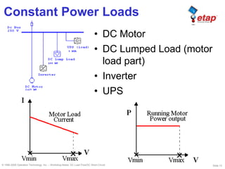
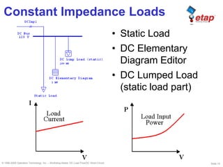
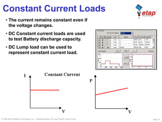
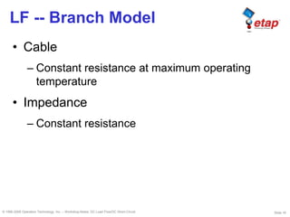
© 1996-2009 Operation Technology, Inc. – Workshop Notes: DC Load Flow/DC Short-Circuit
DC Load Flow
DC Short-Circuit
Slide 2© 1996-2009 Operation Technology, Inc. – Workshop Notes: DC Load Flow/DC Short-Circuit
Why DC System Studies?
DC systems play an ever increasing role in:
• Substation and generating station instrumentation
and control systems (IEEE Std 946)
• Class 1E power system for nuclear power
generation station – providing power to reactor trip
system and engineered safety features
(IEEE Std 308)
• Provide back-up energy for emergencies in
hospital, generation station, production line, data
processing and communication, etc.
(IEEE Std 446 Orange Book)
Slide 3© 1996-2009 Operation Technology, Inc. – Workshop Notes: DC Load Flow/DC Short-Circuit
Why DC System Studies?
• Reliable – Having redundant sources and
can operate under single failure in the
system
• Adequate – Capable of providing sufficient
power at required system voltage in
specified time duration
Due to the importance of DC systems,
it must be:
Slide 4© 1996-2009 Operation Technology, Inc. – Workshop Notes: DC Load Flow/DC Short-Circuit
Type of Studies
• Load Flow – Determine system operating
conditions and verify equipment continuous ratings
• Short-Circuit Calculation – Determine system SC
current and verify equipment SC capability
• Battery Sizing and Discharge Calculation (IEEE
Std 485) – Determine sufficient battery size to
provide required power in specified time duration
• Control System Diagram, Vd Calc – Determine
and verify sufficient voltage for control circuit
operation
Slide 5© 1996-2009 Operation Technology, Inc. – Workshop Notes: DC Load Flow/DC Short-Circuit
DC System Elements
• DC System Source
– Charger/Converter and Battery
• DC System Loads
– Static Load, DC Motor, Lump Load , and DC Elementary
Diagram
• DC System Branch
– Cable and Impedance
• DC System Other Elements
– Bus and Node, DC Converter, DC Composite Motor, and
Inverter
Slide 6© 1996-2009 Operation Technology, Inc. – Workshop Notes: DC Load Flow/DC Short-Circuit
Purpose of DC LF Study
• To determine system operating conditions --
bus voltages, branch flows, and power
provided by various sources
• To verify equipment continuous ratings
Slide 7© 1996-2009 Operation Technology, Inc. – Workshop Notes: DC Load Flow/DC Short-Circuit
LF -- Battery Model
• Constant voltage source behind battery
resistance .
• Active voltage source if Vbus < Vrate
• Inactive voltage source if Vbus > Vrate
Slide 8© 1996-2009 Operation Technology, Inc. – Workshop Notes: DC Load Flow/DC Short-Circuit
LF -- Charger Model
• Constant voltage source, if I < Imax
• Constant current source, if I > Imax,
injecting Imax into system
• Inactive if Vout < Vbus
• Constant power load to AC system
Slide 9© 1996-2009 Operation Technology, Inc. – Workshop Notes: DC Load Flow/DC Short-Circuit
LF -- Inverter Model
• Constant voltage source to AC system
• Constant power load to DC system
Slide 10© 1996-2009 Operation Technology, Inc. – Workshop Notes: DC Load Flow/DC Short-Circuit
LF -- UPS Model
• If auction diode option is checked, then DC
system provides power to UPS AC load if
Vdc > Vac.
• If auction diode option is not checked…
– and UPS AC input bus is energized, then UPS
becomes a source to DC system, similar to a
charger.
– and UPS AC input bus is not energized, then DC
system provides power to UPS AC load.
• Constant power load to DC system
Slide 11© 1996-2009 Operation Technology, Inc. – Workshop Notes: DC Load Flow/DC Short-Circuit
LF -- DC Converter Model
• Constant voltage source to output bus, if
I<Imax
• Constant current source to output bus, if
I>Imax, injecting Imax into the bus
• Constant current load to the input bus
• Inactive if Vout < Vbus
Slide 12© 1996-2009 Operation Technology, Inc. – Workshop Notes: DC Load Flow/DC Short-Circuit
LF -- Load Model
• Motor
– Constant P load, if Vmin <V<Vmax;
– Constant Z load, otherwise
• Static Load
– Constant resistance load
• Lumped Load
– Constant power, resistance, current load
• Elementary Diagram Load
– Constant resistance load
Slide 13© 1996-2009 Operation Technology, Inc. – Workshop Notes: DC Load Flow/DC Short-Circuit
Constant Power Loads
• DC Motor
• DC Lumped Load (motor
load part)
• Inverter
• UPS
Slide 14© 1996-2009 Operation Technology, Inc. – Workshop Notes: DC Load Flow/DC Short-Circuit
• Static Load
• DC Elementary
Diagram Editor
• DC Lumped Load
(static load part)
Constant Impedance Loads
Slide 15© 1996-2009 Operation Technology, Inc. – Workshop Notes: DC Load Flow/DC Short-Circuit
• The current remains constant even if
the voltage changes.
• DC Constant current loads are used
to test Battery discharge capacity.
• DC Lump load can be used to
represent constant current load.
Constant Current Loads
Slide 16© 1996-2009 Operation Technology, Inc. – Workshop Notes: DC Load Flow/DC Short-Circuit
LF -- Branch Model
• Cable
– Constant resistance at maximum operating
temperature
• Impedance
– Constant resistance
Slide 17© 1996-2009 Operation Technology, Inc. – Workshop Notes: DC Load Flow/DC Short-Circuit
LF- Adjustments
• Cable Length Tolerance
– Positive adjustment for DCLF & DCBS
– Negative adjustment for DCSC
• Cable Resistance based on Temperature
– Copper / Aluminum
– Use Maximum Temperature for DCLF & DCBS
– Use Minimum Temperature for DCSC
Slide 18© 1996-2009 Operation Technology, Inc. – Workshop Notes: DC Load Flow/DC Short-Circuit
Purpose of DC SC Study
• To determine short-circuit fault currents and
fault contributions from different sources.
– Maximum fault current
– System equivalent impedance at fault location
– Time constant for SC current rise
• To verify protective equipment capability.
Slide 19© 1996-2009 Operation Technology, Inc. – Workshop Notes: DC Load Flow/DC Short-Circuit
SC -- Battery Model
• Constant voltage source -- (Voc) behind
battery resistance
– Voc may be calculated based on battery specific
gravity (SG)
– Open Circuit Voltage (Voc) from library
– User-Defined value (% Vpc)
• Constant current source
– Ksc * One_Min_Discharge_Current
Slide 20© 1996-2009 Operation Technology, Inc. – Workshop Notes: DC Load Flow/DC Short-Circuit
SC -- Charger Model
• Constant voltage source behind AC system
impedance (converted to DC side)
• Constant current source, Ksc * Ifl
Slide 21© 1996-2009 Operation Technology, Inc. – Workshop Notes: DC Load Flow/DC Short-Circuit
SC -- UPS & Inverter Model
• UPS -- Constant current source
Ksc * Ifl
• Inverter -- Not considered in DC short-circuit
study
Slide 22© 1996-2009 Operation Technology, Inc. – Workshop Notes: DC Load Flow/DC Short-Circuit
SC -- DC Converter Model
• Constant current source, Ksc * Ifl, to faults
on output side of the system
• Short-circuit contribution calculation stops at
DC converters
Slide 23© 1996-2009 Operation Technology, Inc. – Workshop Notes: DC Load Flow/DC Short-Circuit
SC -- Load Model
• Motor – constant voltage behind transient
impedance
• Static load and ED load are considered in
calculation
Slide 24© 1996-2009 Operation Technology, Inc. – Workshop Notes: DC Load Flow/DC Short-Circuit
SC -- Branch Model
• Cable
– Constant resistance at minimum operating
temperature
• Impedance
– Constant resistance

ETAP - dc lf and dc sc | DC Load Flow & DC short-Circuit

  • 1.
    © 1996-2009 OperationTechnology, Inc. – Workshop Notes: DC Load Flow/DC Short-Circuit DC Load Flow DC Short-Circuit
  • 2.
    Slide 2© 1996-2009Operation Technology, Inc. – Workshop Notes: DC Load Flow/DC Short-Circuit Why DC System Studies? DC systems play an ever increasing role in: • Substation and generating station instrumentation and control systems (IEEE Std 946) • Class 1E power system for nuclear power generation station – providing power to reactor trip system and engineered safety features (IEEE Std 308) • Provide back-up energy for emergencies in hospital, generation station, production line, data processing and communication, etc. (IEEE Std 446 Orange Book)
  • 3.
    Slide 3© 1996-2009Operation Technology, Inc. – Workshop Notes: DC Load Flow/DC Short-Circuit Why DC System Studies? • Reliable – Having redundant sources and can operate under single failure in the system • Adequate – Capable of providing sufficient power at required system voltage in specified time duration Due to the importance of DC systems, it must be:
  • 4.
    Slide 4© 1996-2009Operation Technology, Inc. – Workshop Notes: DC Load Flow/DC Short-Circuit Type of Studies • Load Flow – Determine system operating conditions and verify equipment continuous ratings • Short-Circuit Calculation – Determine system SC current and verify equipment SC capability • Battery Sizing and Discharge Calculation (IEEE Std 485) – Determine sufficient battery size to provide required power in specified time duration • Control System Diagram, Vd Calc – Determine and verify sufficient voltage for control circuit operation
  • 5.
    Slide 5© 1996-2009Operation Technology, Inc. – Workshop Notes: DC Load Flow/DC Short-Circuit DC System Elements • DC System Source – Charger/Converter and Battery • DC System Loads – Static Load, DC Motor, Lump Load , and DC Elementary Diagram • DC System Branch – Cable and Impedance • DC System Other Elements – Bus and Node, DC Converter, DC Composite Motor, and Inverter
  • 6.
    Slide 6© 1996-2009Operation Technology, Inc. – Workshop Notes: DC Load Flow/DC Short-Circuit Purpose of DC LF Study • To determine system operating conditions -- bus voltages, branch flows, and power provided by various sources • To verify equipment continuous ratings
  • 7.
    Slide 7© 1996-2009Operation Technology, Inc. – Workshop Notes: DC Load Flow/DC Short-Circuit LF -- Battery Model • Constant voltage source behind battery resistance . • Active voltage source if Vbus < Vrate • Inactive voltage source if Vbus > Vrate
  • 8.
    Slide 8© 1996-2009Operation Technology, Inc. – Workshop Notes: DC Load Flow/DC Short-Circuit LF -- Charger Model • Constant voltage source, if I < Imax • Constant current source, if I > Imax, injecting Imax into system • Inactive if Vout < Vbus • Constant power load to AC system
  • 9.
    Slide 9© 1996-2009Operation Technology, Inc. – Workshop Notes: DC Load Flow/DC Short-Circuit LF -- Inverter Model • Constant voltage source to AC system • Constant power load to DC system
  • 10.
    Slide 10© 1996-2009Operation Technology, Inc. – Workshop Notes: DC Load Flow/DC Short-Circuit LF -- UPS Model • If auction diode option is checked, then DC system provides power to UPS AC load if Vdc > Vac. • If auction diode option is not checked… – and UPS AC input bus is energized, then UPS becomes a source to DC system, similar to a charger. – and UPS AC input bus is not energized, then DC system provides power to UPS AC load. • Constant power load to DC system
  • 11.
    Slide 11© 1996-2009Operation Technology, Inc. – Workshop Notes: DC Load Flow/DC Short-Circuit LF -- DC Converter Model • Constant voltage source to output bus, if I<Imax • Constant current source to output bus, if I>Imax, injecting Imax into the bus • Constant current load to the input bus • Inactive if Vout < Vbus
  • 12.
    Slide 12© 1996-2009Operation Technology, Inc. – Workshop Notes: DC Load Flow/DC Short-Circuit LF -- Load Model • Motor – Constant P load, if Vmin <V<Vmax; – Constant Z load, otherwise • Static Load – Constant resistance load • Lumped Load – Constant power, resistance, current load • Elementary Diagram Load – Constant resistance load
  • 13.
    Slide 13© 1996-2009Operation Technology, Inc. – Workshop Notes: DC Load Flow/DC Short-Circuit Constant Power Loads • DC Motor • DC Lumped Load (motor load part) • Inverter • UPS
  • 14.
    Slide 14© 1996-2009Operation Technology, Inc. – Workshop Notes: DC Load Flow/DC Short-Circuit • Static Load • DC Elementary Diagram Editor • DC Lumped Load (static load part) Constant Impedance Loads
  • 15.
    Slide 15© 1996-2009Operation Technology, Inc. – Workshop Notes: DC Load Flow/DC Short-Circuit • The current remains constant even if the voltage changes. • DC Constant current loads are used to test Battery discharge capacity. • DC Lump load can be used to represent constant current load. Constant Current Loads
  • 16.
    Slide 16© 1996-2009Operation Technology, Inc. – Workshop Notes: DC Load Flow/DC Short-Circuit LF -- Branch Model • Cable – Constant resistance at maximum operating temperature • Impedance – Constant resistance
  • 17.
    Slide 17© 1996-2009Operation Technology, Inc. – Workshop Notes: DC Load Flow/DC Short-Circuit LF- Adjustments • Cable Length Tolerance – Positive adjustment for DCLF & DCBS – Negative adjustment for DCSC • Cable Resistance based on Temperature – Copper / Aluminum – Use Maximum Temperature for DCLF & DCBS – Use Minimum Temperature for DCSC
  • 18.
    Slide 18© 1996-2009Operation Technology, Inc. – Workshop Notes: DC Load Flow/DC Short-Circuit Purpose of DC SC Study • To determine short-circuit fault currents and fault contributions from different sources. – Maximum fault current – System equivalent impedance at fault location – Time constant for SC current rise • To verify protective equipment capability.
  • 19.
    Slide 19© 1996-2009Operation Technology, Inc. – Workshop Notes: DC Load Flow/DC Short-Circuit SC -- Battery Model • Constant voltage source -- (Voc) behind battery resistance – Voc may be calculated based on battery specific gravity (SG) – Open Circuit Voltage (Voc) from library – User-Defined value (% Vpc) • Constant current source – Ksc * One_Min_Discharge_Current
  • 20.
    Slide 20© 1996-2009Operation Technology, Inc. – Workshop Notes: DC Load Flow/DC Short-Circuit SC -- Charger Model • Constant voltage source behind AC system impedance (converted to DC side) • Constant current source, Ksc * Ifl
  • 21.
    Slide 21© 1996-2009Operation Technology, Inc. – Workshop Notes: DC Load Flow/DC Short-Circuit SC -- UPS & Inverter Model • UPS -- Constant current source Ksc * Ifl • Inverter -- Not considered in DC short-circuit study
  • 22.
    Slide 22© 1996-2009Operation Technology, Inc. – Workshop Notes: DC Load Flow/DC Short-Circuit SC -- DC Converter Model • Constant current source, Ksc * Ifl, to faults on output side of the system • Short-circuit contribution calculation stops at DC converters
  • 23.
    Slide 23© 1996-2009Operation Technology, Inc. – Workshop Notes: DC Load Flow/DC Short-Circuit SC -- Load Model • Motor – constant voltage behind transient impedance • Static load and ED load are considered in calculation
  • 24.
    Slide 24© 1996-2009Operation Technology, Inc. – Workshop Notes: DC Load Flow/DC Short-Circuit SC -- Branch Model • Cable – Constant resistance at minimum operating temperature • Impedance – Constant resistance