This document provides an overview of control system diagrams (CSDs) and how they can be modeled, simulated, and integrated with other systems. Key points include:
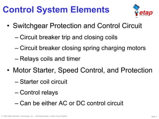
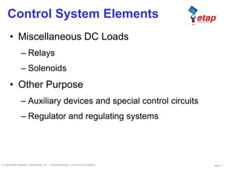
- CSDs can model elements like circuit breakers, motor starters, and other control devices and loads.
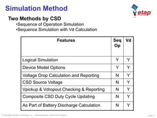
- The CSD allows editing elements, connections, and engineering data, and simulating operations.
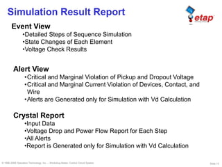
- Simulation can analyze control logic, device duty cycles, voltage drops, and detect alerts.
- CSDs can have their duty cycles and simulations updated from other systems like elementary diagrams or battery discharge studies to integrate control and power systems modeling.