Downloaded 13 times

![IJRET: International Journal of Research in Engineering and Technology eISSN: 2319-1163 | pISSN: 2321-7308
_______________________________________________________________________________________
Volume: 03 Special Issue: 12 | ICAESA - 2014 | Jun-2014, Available @ http://www.ijret.org 12
0 2 4 6 8 10 12
x 10
4
-500
-400
-300
-200
-100
0
100
200
300
400
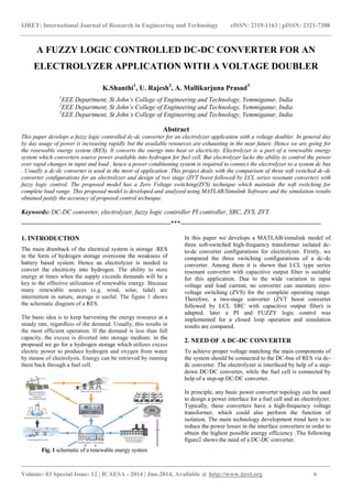
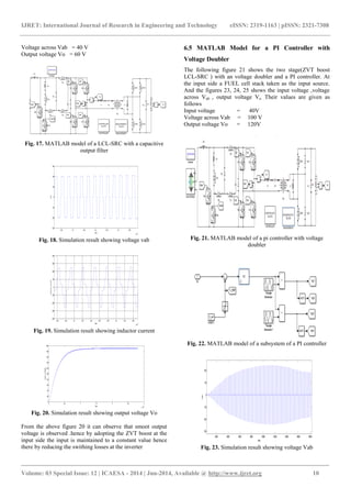
Fig. 32. Simulation result showing voltage Vab
In the above figure 27 a fuzzy logic controller was
implemented with mamdani fuzzy inference type.when
compared the results of PI and fuzzy controller from the
figures 24and 30 it can be shown that even low voltage
application also the fuzzy controller can reduce the output
distortions.And also it maintains the ZVS for all switches
reducing the switching losses.
fuell stack rating = 6KW-45V DC
no of cells = 65
voltage at Vab = 100 v
output voltage = 120 V
7. CONCLUSIONS
In this paper a fuzzy logic controlled DC-DC converter for an
electrolyzer application has been implemented using
MATLAB/simulink. Among available converter
configurations it is shown that the a ZVT BOOST along with
LCL –SRC converter is best one for the electrolyzer. To
reduce the output distortions a PI controller was kept in order
to reduce the steady state error. A voltage doubler introduced
in the circuit acts as both rectifier and as voltage doubler .the
simulation results are checked for both fuzzy and PI
controller. It is shown that by using fuzzy logic controlled
converter the conversion can be operated smoothly and
efficiently for electrolyzer application compared to the other
converters. And the output voltage range also doubled .
REFERENCES
[1] D. Shapiro, J. Duffy, M. Kimble, and M. Pien, “Solar-powered
regenerative PEM electrolyzer/fuel cell
system,” J. Solar Energy, vol. 79, pp. 544–550, 2005.
[2] X. Zhang, H. S.-H. Chung, X. Ruan, and A. Ioinovici,
“A ZCS full-bridge converter without voltage
overstress on the switches,” IEEE Trans.
PowerElectron., vol. 25, no. 3, pp. 686–698, Mar. 201
[3] D. S. Gautam and A. K. S. Bhat, “A two-stage soft-switched
converter for electrolyser application,” in
Proc. Nat. Power Syst. Conf., Mumbai, India, 2008,
pp. 524–528.
[4] A.K.S. Bhat, "Analysis and design of LCL-type
resonant converter", IEEE Trans. on Industrial
Electronics, vol. 41, no. 1, pp. 118-124, Feb. 1994.
[5] A.K.S. Bhat, "Analysis and design of a fixed
frequency LCL-type series resonant converter," IEEE
Trans. on Aerospace and Electronic Systems,vol. 31,
no. 1, Jan. 1995, 125-137.
[6] Ahmadi, P., Dincer, I., Rosen, M.A., 2013. Energy
and exergy analyses of hydrogen production via solar-boosted
ocean thermal energy conversion and PEM
electrolysis. International Journal of Hydrogen
Energy, 38 (4) : 1795- 1805.
[doi:10.1016/j.ijhydene.2012.11.025]
[7] Arriaga, L.G., Martinez, W., Cano, U., Blud, H.,
2007. Direct coupling of a solar-hydrogen system in
Mexico. International Journal of Hydrogen Energy,
32 (13): 2247- 2252.
[doi:10.1016/j.ijhydene.2006.10.067]
[8] Y. Jang and M. M. Jovanovic, “A new family of full-bridge
ZVS converters,” IEEE Trans. Power
Electron., vol. 19, no. 3, pp. 701–708, May 2004.
[9] H. Bodur and A. F. Bakan, “A new ZVT-PWM DC-DC
converter,” IEEE Trans. on Power Electr., vol.
17, no. 1, Jan. 2002, pp. 40-47.
[10] R. Streit and D. Tollik, “High efficiency telecom
rectifier using a novel soft-switched boost based input
current shaper”, IEEE INTELC Conf. Record, 1991,
pp.720-726.
[11] Ferraro, “An overview of low-loss snubber
technology for transistor converters,” in Proc. IEEE
Power Electron. Spec. Conf., 1982, pp.466–477.
[12] G. Hua, C. S. Leu, Y. Jiang, and F. C. Y. Lee, “Novel
zero-voltagetransition PWM converters,” IEEE Trans.
Power Electron., vol. 9, pp. 213–219, Mar. 1994.
601–606, Nov. 1994.
[13] D. S. Gautam and A. K. S. Bhat, “A two-stage soft-switched
converter for electrolyser application,” in
Proc. Nat. Power Syst. Conf., Mumbai, India, 2008,
pp. 524–528.](https://image.slidesharecdn.com/afuzzylogiccontrolleddc-dcconverterforan-140827000004-phpapp02/85/A-fuzzy-logic-controlled-dc-dc-converter-for-an-7-320.jpg)

This document presents a fuzzy logic controlled DC-DC converter designed for electrolyzer applications within renewable energy systems. It discusses the necessity of such converters to manage energy storage and power supply variations, along with the simulation results of various soft-switched high-frequency transformer isolated configurations. The analysis highlights the performance improvements achieved through the incorporation of fuzzy logic control in maintaining zero-voltage switching across diverse operating conditions.


![6.[36 45]seven level modified cascaded inverter for induction motor drive app...](https://cdn.slidesharecdn.com/ss_thumbnails/6-36-45sevenlevelmodifiedcascadedinverterforinductionmotordriveapplications-111118181646-phpapp02-thumbnail.jpg?width=640&height=640&fit=bounds)


