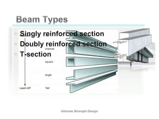
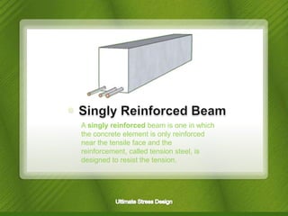
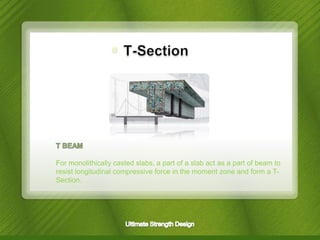
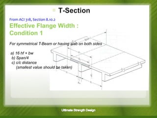
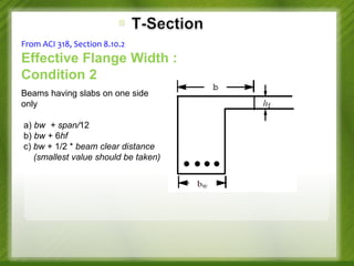
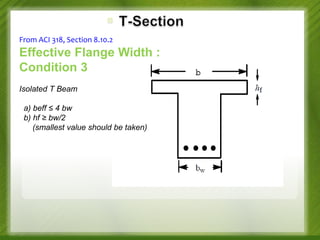
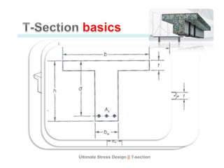
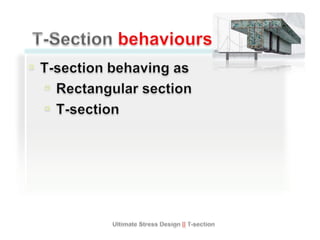
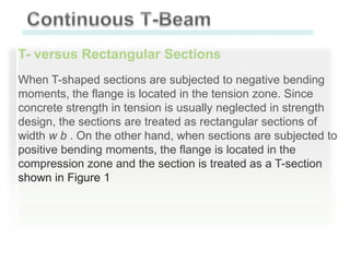
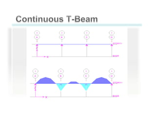
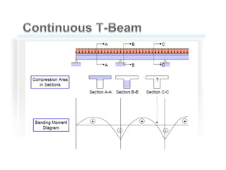
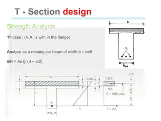
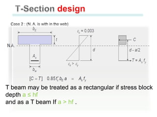
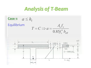
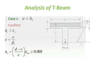
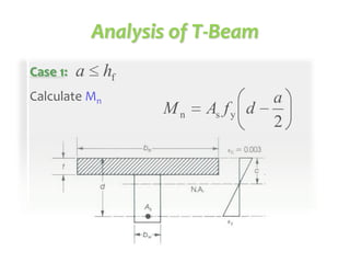
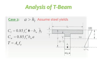
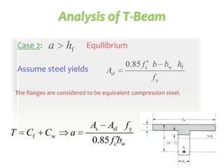
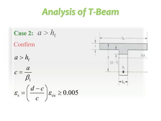
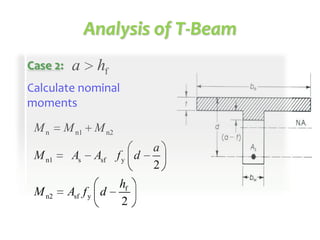
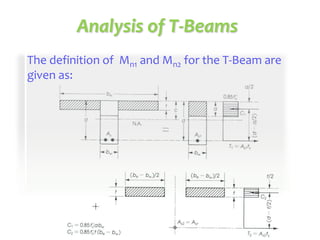
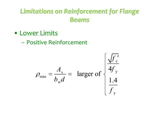
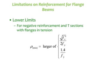
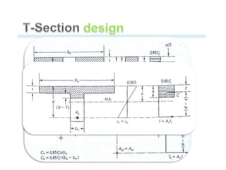
13. A singly reinforced beam is one in which
the concrete element is only reinforced
near the tensile face and the
reinforcement, called tension steel, is
designed to resist the tension.
14. A doubly reinforced beam is one in which besides the tensile
reinforcement the concrete element is also reinforced near the
compressive face to help the concrete resist compression. The
latter reinforcement is called compression steel. When the
compression zone of a concrete is inadequate to resist the
compressive moment (positive moment), extra reinforcement has
to be provided if the architect limits the dimensions of the section.
15. For monolithically casted slabs, a part of a slab act as a part of beam to
resist longitudinal compressive force in the moment zone and form a TSection.
16. From ACI 318, Section 8.10.2
Effective Flange Width :
Condition 1
For symmetrical T-Beam or having slab on both sides
a) 16 hf + bw
b) Span/4
c) c/c distance
(smallest value should be taken)
17. From ACI 318, Section 8.10.2
Effective Flange Width :
Condition 2
Beams having slabs on one side
only
a) bw + span/12
b) bw + 6hf
c) bw + 1/2 * beam clear distance
(smallest value should be taken)
18. From ACI 318, Section 8.10.2
Effective Flange Width :
Condition 3
Isolated T Beam
a) beff ≤ 4 bw
b) hf ≥ bw/2
(smallest value should be taken)
19.
20.
21. T- versus Rectangular Sections
When T-shaped sections are subjected to negative bending
moments, the flange is located in the tension zone. Since
concrete strength in tension is usually neglected in strength
design, the sections are treated as rectangular sections of
width w b . On the other hand, when sections are subjected to
positive bending moments, the flange is located in the
compression zone and the section is treated as a T-section
shown in Figure 1
22.
23.
24. Strength Analysis :
1st case : (N.A. is with in the flange)
Analyze as a rectangular beam of width b = beff
Mn = As fy (d − a/2)
25. Case 2 : (N. A. is with in the web)
T beam may be treated as a rectangular if stress block
depth a ≤ hf
and as a T beam If a > hf .
29. Analysis of T-Beam
Case 2:
a
hf
Assume steel yields
Cf
0.85 f c b bw hf
Cw
0.85 f c bw a
T
As f y
30. Analysis of T-Beam
Case 2:
a
hf
Equilibrium
Assume steel yields
Asf
0.85 f c b bw hf
fy
The flanges are considered to be equivalent compression steel.
T
Cf
Cw
a
As
Asf f y
0.85 fcbw
34. Limitations on Reinforcement for Flange
Beams
• Lower Limits
– Positive Reinforcement
min
As
b wd
larger of
fc
4f y
1.4
fy
35. Limitations on Reinforcement for Flange
Beams
• Lower Limits
– For negative reinforcement and T sections
with flanges in tension
fc
(min)
larger of
2f y
1.4
fy