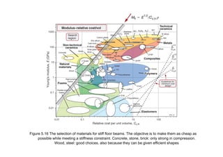
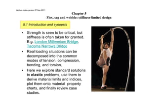
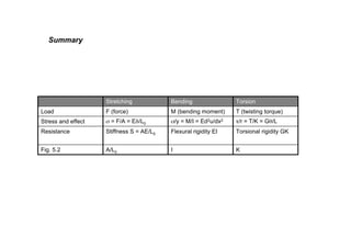
This document discusses stiffness-limited design and standard solutions to elastic problems. It covers five topics:
1) Elastic extension or compression, where stiffness S is defined as AE/L0
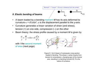
2) Elastic bending of beams, where flexural rigidity EI relates bending moment M to curvature κ
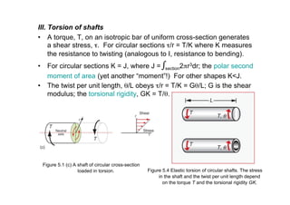
3) Torsion of shafts, where torsional rigidity GK relates torque T to twist θ/L
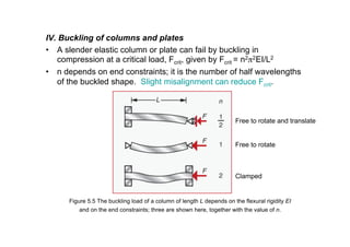
4) Buckling of columns and plates, where critical buckling load depends on flexural rigidity EI
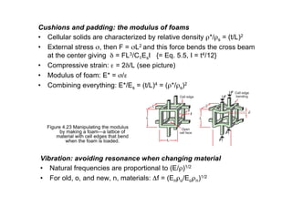
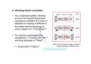
5) Vibrating beams and plates, where natural frequency depends on flexural rigidity EI and mass m.
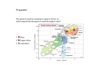
Material indices like E/ρ, E1


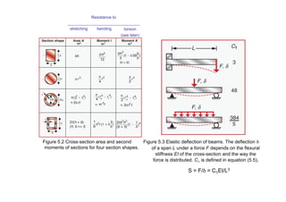


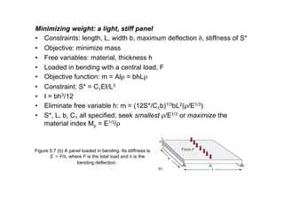
![Figure 5.7 (c) A beam of square section, loaded
in bending. Its stiffness is S = F/δ, where F
is the load and δ is the bending deflection.
Minimizing weight: a light, stiff beam
• Constraints: the shape must be self-similar (all dimensions change
in proportion as the overall size is varied, a simplification) length, L,
square section, maximum deflection δ, stiffness of S*
• Objective: minimize mass
• Free variables: material, area of cross section
• Loaded in bending with a central load, F
• Objective function: m = ALρ = b2Lρ
• Constraint: S* = C1EI/L3
• I = b4/12 = A2/12 [other shape: always a constant times A2]
• Eliminate free variable b: m = (12S*L3/C1)1/2L(ρ/E1/2)
• S*, L, C1 all specified; seek smallest ρ/E1/2 or maximize the material
index Mb = E1/2/ρ; other shapes give the same answer, only with a
different factor than 12.
Factor 12: incorrect in book (p. 95, top)](https://image.slidesharecdn.com/materiaalkunde1slideschapter5-230319081127-2b7a37c7/85/Materiaalkunde_1_slides_chapter5-pdf-21-320.jpg)