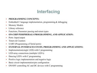
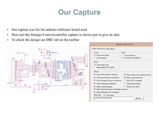
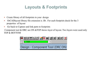
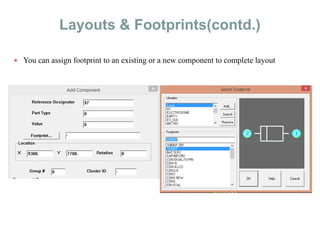
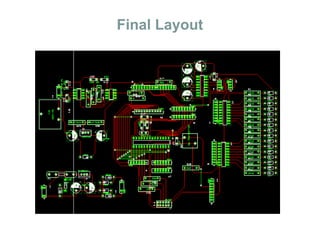
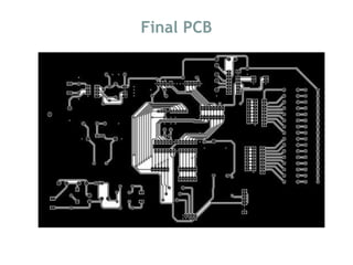
ARDUINO & PCB design
(basics)
What is a Microcontroller
• A small computer on a single chip containing a processor, memory,
and input/output
• Typically "embedded" inside some device that they control
• A microcontroller is often small and low cost
The Arduino Development Board
The Arduino Microcontroller: Atmel ARV
Atmega 8
What is the Arduino
Our First Program
Interfacing
 PROGRAMMING CONCEPTS:
 Embedded C language implementation, programming,& debugging
 Memory Models
 Library reference
 Functions, Parameter passing and return types
 ON-CHIP PERIPHERALS PROGRAMMING, AND APPLICATION:
 Ports: Input/output
 Timers & Counters
 UART (Programming of Serial ports)
 EXTERNAL INTERFACES STUDY, PROGRAMMING AND APPLICATIONS:
 Implementation(single LED) with C programming
 LED array connections (multiple LED’s)
 Dancing LED’s with C programming
 Positive logic implementation and negative logic
 Basic circuit implementation/pin configuration
 ON/OFF controlling AC and DC devices with C programming
Interfacing (contd.)
 LCD
 16×2 LCD hardware connections
 Displaying own text on 16×2 LCD with C programming
 LCD interfacing with push buttons in C program
 Custom Character Generation
 Combining LCD and switch for a password system
 FLAME SENSOR RECEIVER MODULE
 Application in fire alarm systems
 GAS SENSOR
 Air Quality Gas Sensor MQ-135
 Can be used in alcohol sensor systems
 BLUETOOTH
 HC-06 Bluetooth Module Serial port Bluetooth
 Easy to use as it is based on Rx-Tx model
 Can be connected easily to smartphones and used even with voice control
FLAME SENSOR 16X2 LCD
MQ135 GAS SENSOR
Interfacing (contd.)
 RFID
 RFID module RDM-630
 Can be used in any kind of identification system
 Passive tags used to interact with module
 Doesn’t require line of sight like bar code reader
 Easy to use as it is based on Rx-Tx model
 Short range RFID used in industrial data collection
 ULTRASONIC MODULE
 HC-SR04 Ultrasonic Module
 You only need to supply a short 10uS pulse to the trigger input to start the ranging, and then the
module will send out an 8 cycle burst of ultrasound at 40 kHz and raise its echo. The Echo is a
distance object that is pulse width and the range in proportion .You can calculate the range
through the time interval between sending trigger signal and receiving echo signal.
Interfacing (contd.)
 RF RX-TX MODULES
 RF transmitter FS1000A
 3 pin 433MHz RF transmitter
 2 arduino UNO boards to be used to catch the data through RF module
 RF receiver PCR2A is a 4-pin receiver module
 If receiver is receiving the signals from transmitter , then LED on both the boards must blink
simultaneously.
 Can be used with HT12E/D encoder-decoder pair
 HT12E converts parallel data from switches to serial form
 HT12D converts serially received data from transmitter to parallel output
 Parallel output is displayed using LEDs
RFID HC-SR04
Interfacing (contd.)
 RELAY & DC MOTOR
 Relays are simple switches operated electrically and mechanically.
 Used when low power signal is used to control a circuit
 Used when one signal is used to control many circuits
 Basically of 4 types :- 1) SPST 2) SPDT 3) DPST 4) DPDT
 For standard unidirectional motor we use SPDT type
Interfacing (contd.)
 H-BRIDGE CONTROL FOR DC-MOTOR
 Electronic circuit that allows voltage to be applied across a load in either direction
 Used in motor control
 H-bridge can be realized using semiconductor devices or using relay or can be purchased in the
form of an IC
 The dc motor can be run in both the directions unlike the unidirectional motion as seen in SPDT
model
Interfacing (contd.)
 DPDT RELAY FOR MOTOR
 DPDT relay is an 8-terminal device and stands for dual POLE dual THROW
Interfacing (contd.)
 H-BRIDGE IC FOR DC-MOTOR
 H-bridge can be implemented by an IC-L293D
 A 16-pin IC and can control 2 sets of DC motors simultaneously in any direction
Interfacing(contd.)
 GPS MODULE
 GPS module NEO-6M
 Arduino code used read the info like, date, time, location in view from NMEA data streams
 The most common string $GPRMC was decoded
 $GPRMC string contains following data :- time stamp , current latitude & longitude, speed
over ground in knots, date of fix
 GSM MODULE
 GSM module called SIM900
 Supports communication in 900MHz band
 Works on a 12V input
 Once, connection is established status LED will blink continuously every 3 seconds
 Instruction set for GSM
ata =(attend call) ath=(reject call)
AT+CMGF=1 (sets GSM in text mode)
AT+CGMR=1 (displays first text message in memory)
AT+ CGMD=2 (delete 2nd message frrom memory)
GPS SIM900(GSM)
Interfacing(contd.)
 MPU-6050
 InvenSense MPU-6050 sensor contains a MEMS accelerometer and a MEMS gyro in a single
chip.
 It is very accurate, as it contains 16-bits analog to digital conversion hardware for each channel.
 it captures the x, y, and z channel at the same time. The sensor uses the I2C-bus to interface with
the Arduino.
 It always acts as a slave with the SDA & SCL pins connected to I2C bus.
 KEYPAD
 4X4 matrix keypad used
 Princple to detect the key press & decoding logic for key pressed is same as keyboard for
microprocessor
 Same logic of grounding the rows and checking columns and debounce
MPU-6050 KEYPAD
Introduction to Or CAD for Board
Design
Using Capture and Layout
Before We Start
What is a schematic ?
--The board schematic is the logical representation of physical
implementation.
Create a project in Capture
Project Navigator
 The .opjfile is the
Capture project File
 The .dsnfile is the
schematics
 The .olbfile is the
Capture library file
Drawing Parts & Capture
Name
 – Use Part Number with package information
Ref Designators
– Ufor IC, R for Resistor, C for Capacitor, L for inductor,
X forOscillator, J for Connector, JP for Jumper, etc.
Packages
 – PCB Footprint can be linked to Layout
Multiple Part
 – Homogenous
 – Heterogeneous
Pins
 – Polarity
 – Number or letter
 – Symbol
Our Capture
 Our capture was for the arduino reference board used
 Here just the Atmega 8 microcontroller capture is shown just to give an idea
 To check the design use DRC tab on the toolbar
Layouts & Footprints
 Create library of all footprints in your design
 OrCADlayout library file extension is .llb . For each footprint check for the 3
properties of layout
 Go back to Capture and link parts to footprints
Component tool & DRC are ON &TOP shows layer of layout. Two layers were used only
TOP & BOTTOM
Layouts & Footprints(contd.)
 You can assign footprint to an existing or a new component to complete layout
Final Layout
Final PCB

Embedded & pcb design

  • 1.
    ARDUINO & PCBdesign (basics)
  • 2.
    What is aMicrocontroller • A small computer on a single chip containing a processor, memory, and input/output • Typically "embedded" inside some device that they control • A microcontroller is often small and low cost
  • 3.
  • 4.
    The Arduino Microcontroller:Atmel ARV Atmega 8
  • 5.
    What is theArduino
  • 6.
  • 7.
    Interfacing  PROGRAMMING CONCEPTS: Embedded C language implementation, programming,& debugging  Memory Models  Library reference  Functions, Parameter passing and return types  ON-CHIP PERIPHERALS PROGRAMMING, AND APPLICATION:  Ports: Input/output  Timers & Counters  UART (Programming of Serial ports)  EXTERNAL INTERFACES STUDY, PROGRAMMING AND APPLICATIONS:  Implementation(single LED) with C programming  LED array connections (multiple LED’s)  Dancing LED’s with C programming  Positive logic implementation and negative logic  Basic circuit implementation/pin configuration  ON/OFF controlling AC and DC devices with C programming
  • 8.
    Interfacing (contd.)  LCD 16×2 LCD hardware connections  Displaying own text on 16×2 LCD with C programming  LCD interfacing with push buttons in C program  Custom Character Generation  Combining LCD and switch for a password system  FLAME SENSOR RECEIVER MODULE  Application in fire alarm systems  GAS SENSOR  Air Quality Gas Sensor MQ-135  Can be used in alcohol sensor systems  BLUETOOTH  HC-06 Bluetooth Module Serial port Bluetooth  Easy to use as it is based on Rx-Tx model  Can be connected easily to smartphones and used even with voice control
  • 9.
    FLAME SENSOR 16X2LCD MQ135 GAS SENSOR
  • 10.
    Interfacing (contd.)  RFID RFID module RDM-630  Can be used in any kind of identification system  Passive tags used to interact with module  Doesn’t require line of sight like bar code reader  Easy to use as it is based on Rx-Tx model  Short range RFID used in industrial data collection  ULTRASONIC MODULE  HC-SR04 Ultrasonic Module  You only need to supply a short 10uS pulse to the trigger input to start the ranging, and then the module will send out an 8 cycle burst of ultrasound at 40 kHz and raise its echo. The Echo is a distance object that is pulse width and the range in proportion .You can calculate the range through the time interval between sending trigger signal and receiving echo signal.
  • 11.
    Interfacing (contd.)  RFRX-TX MODULES  RF transmitter FS1000A  3 pin 433MHz RF transmitter  2 arduino UNO boards to be used to catch the data through RF module  RF receiver PCR2A is a 4-pin receiver module  If receiver is receiving the signals from transmitter , then LED on both the boards must blink simultaneously.  Can be used with HT12E/D encoder-decoder pair  HT12E converts parallel data from switches to serial form  HT12D converts serially received data from transmitter to parallel output  Parallel output is displayed using LEDs
  • 12.
  • 13.
    Interfacing (contd.)  RELAY& DC MOTOR  Relays are simple switches operated electrically and mechanically.  Used when low power signal is used to control a circuit  Used when one signal is used to control many circuits  Basically of 4 types :- 1) SPST 2) SPDT 3) DPST 4) DPDT  For standard unidirectional motor we use SPDT type
  • 14.
    Interfacing (contd.)  H-BRIDGECONTROL FOR DC-MOTOR  Electronic circuit that allows voltage to be applied across a load in either direction  Used in motor control  H-bridge can be realized using semiconductor devices or using relay or can be purchased in the form of an IC  The dc motor can be run in both the directions unlike the unidirectional motion as seen in SPDT model
  • 15.
    Interfacing (contd.)  DPDTRELAY FOR MOTOR  DPDT relay is an 8-terminal device and stands for dual POLE dual THROW
  • 16.
    Interfacing (contd.)  H-BRIDGEIC FOR DC-MOTOR  H-bridge can be implemented by an IC-L293D  A 16-pin IC and can control 2 sets of DC motors simultaneously in any direction
  • 17.
    Interfacing(contd.)  GPS MODULE GPS module NEO-6M  Arduino code used read the info like, date, time, location in view from NMEA data streams  The most common string $GPRMC was decoded  $GPRMC string contains following data :- time stamp , current latitude & longitude, speed over ground in knots, date of fix  GSM MODULE  GSM module called SIM900  Supports communication in 900MHz band  Works on a 12V input  Once, connection is established status LED will blink continuously every 3 seconds  Instruction set for GSM ata =(attend call) ath=(reject call) AT+CMGF=1 (sets GSM in text mode) AT+CGMR=1 (displays first text message in memory) AT+ CGMD=2 (delete 2nd message frrom memory)
  • 18.
  • 19.
    Interfacing(contd.)  MPU-6050  InvenSenseMPU-6050 sensor contains a MEMS accelerometer and a MEMS gyro in a single chip.  It is very accurate, as it contains 16-bits analog to digital conversion hardware for each channel.  it captures the x, y, and z channel at the same time. The sensor uses the I2C-bus to interface with the Arduino.  It always acts as a slave with the SDA & SCL pins connected to I2C bus.  KEYPAD  4X4 matrix keypad used  Princple to detect the key press & decoding logic for key pressed is same as keyboard for microprocessor  Same logic of grounding the rows and checking columns and debounce
  • 20.
  • 21.
    Introduction to OrCAD for Board Design Using Capture and Layout
  • 22.
    Before We Start Whatis a schematic ? --The board schematic is the logical representation of physical implementation. Create a project in Capture
  • 23.
    Project Navigator  The.opjfile is the Capture project File  The .dsnfile is the schematics  The .olbfile is the Capture library file
  • 24.
    Drawing Parts &Capture Name  – Use Part Number with package information Ref Designators – Ufor IC, R for Resistor, C for Capacitor, L for inductor, X forOscillator, J for Connector, JP for Jumper, etc. Packages  – PCB Footprint can be linked to Layout Multiple Part  – Homogenous  – Heterogeneous Pins  – Polarity  – Number or letter  – Symbol
  • 25.
    Our Capture  Ourcapture was for the arduino reference board used  Here just the Atmega 8 microcontroller capture is shown just to give an idea  To check the design use DRC tab on the toolbar
  • 26.
    Layouts & Footprints Create library of all footprints in your design  OrCADlayout library file extension is .llb . For each footprint check for the 3 properties of layout  Go back to Capture and link parts to footprints Component tool & DRC are ON &TOP shows layer of layout. Two layers were used only TOP & BOTTOM
  • 27.
    Layouts & Footprints(contd.) You can assign footprint to an existing or a new component to complete layout
  • 28.
  • 29.