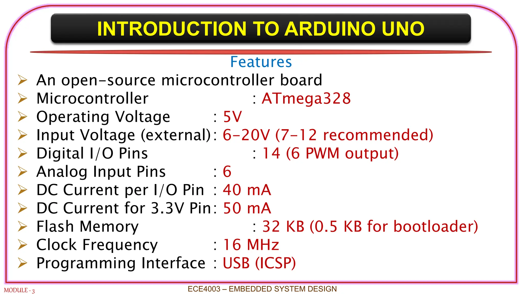
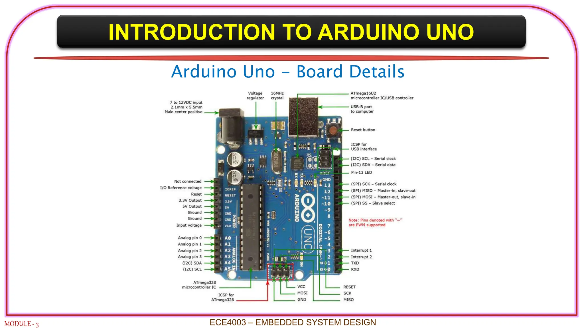
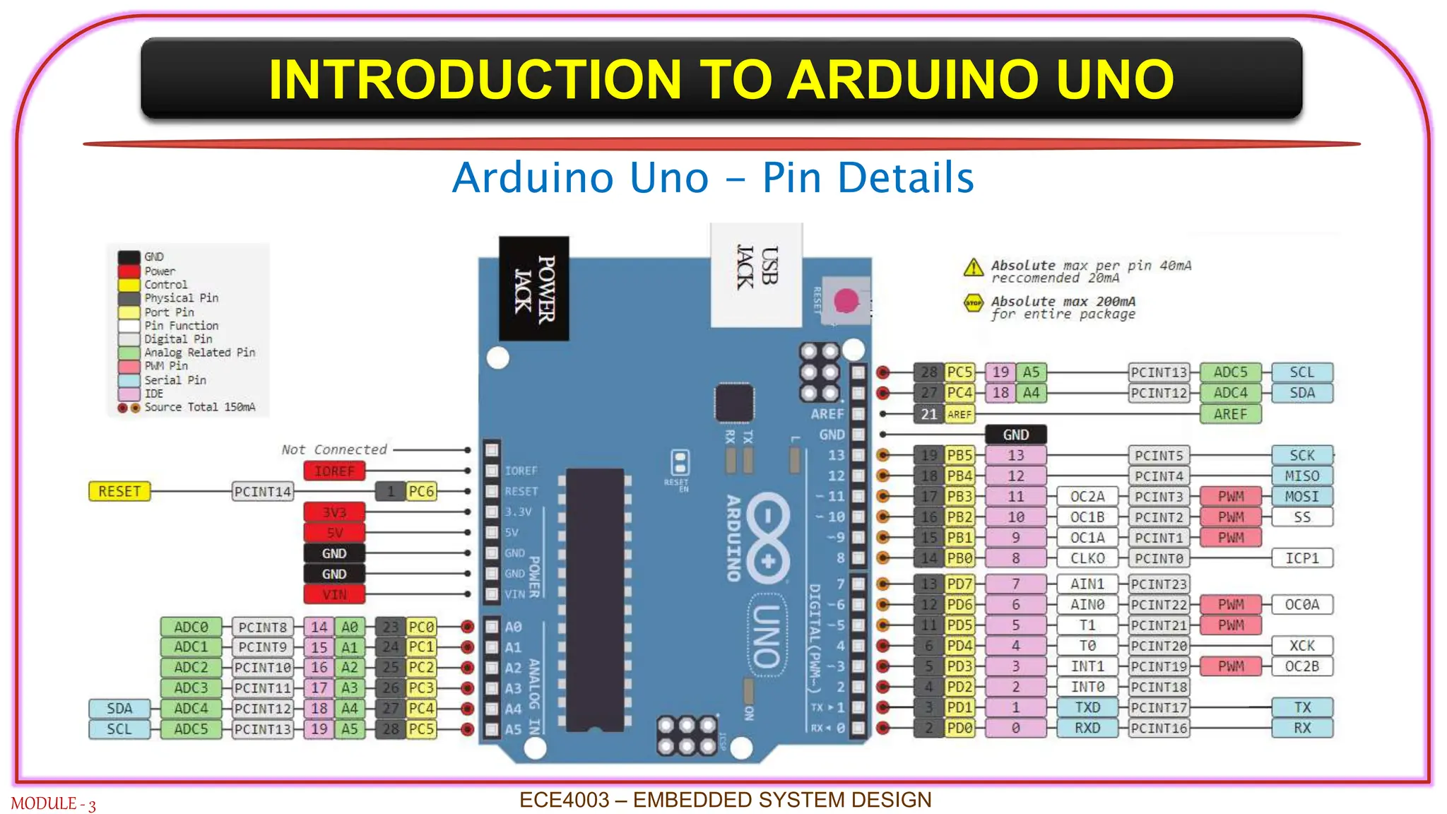
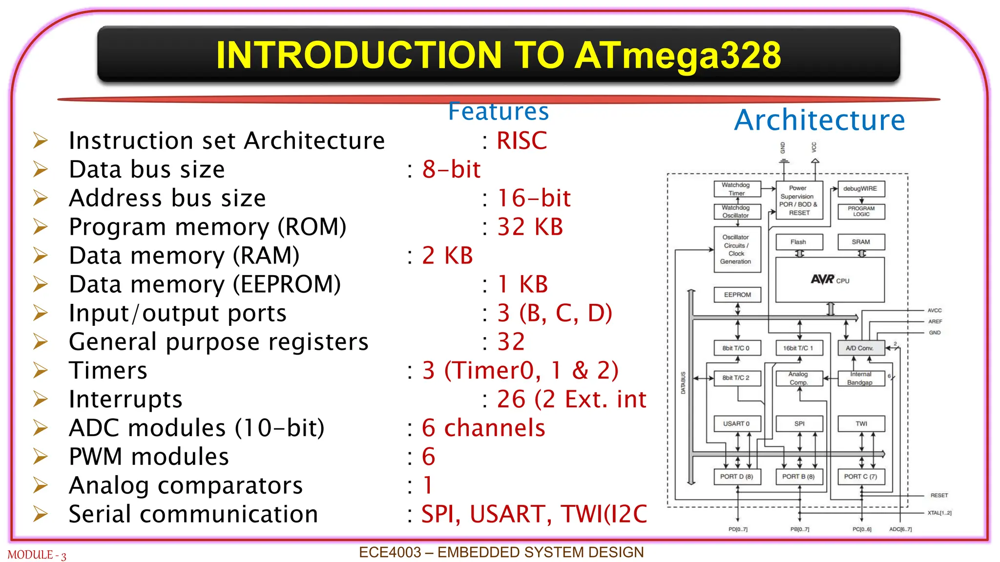
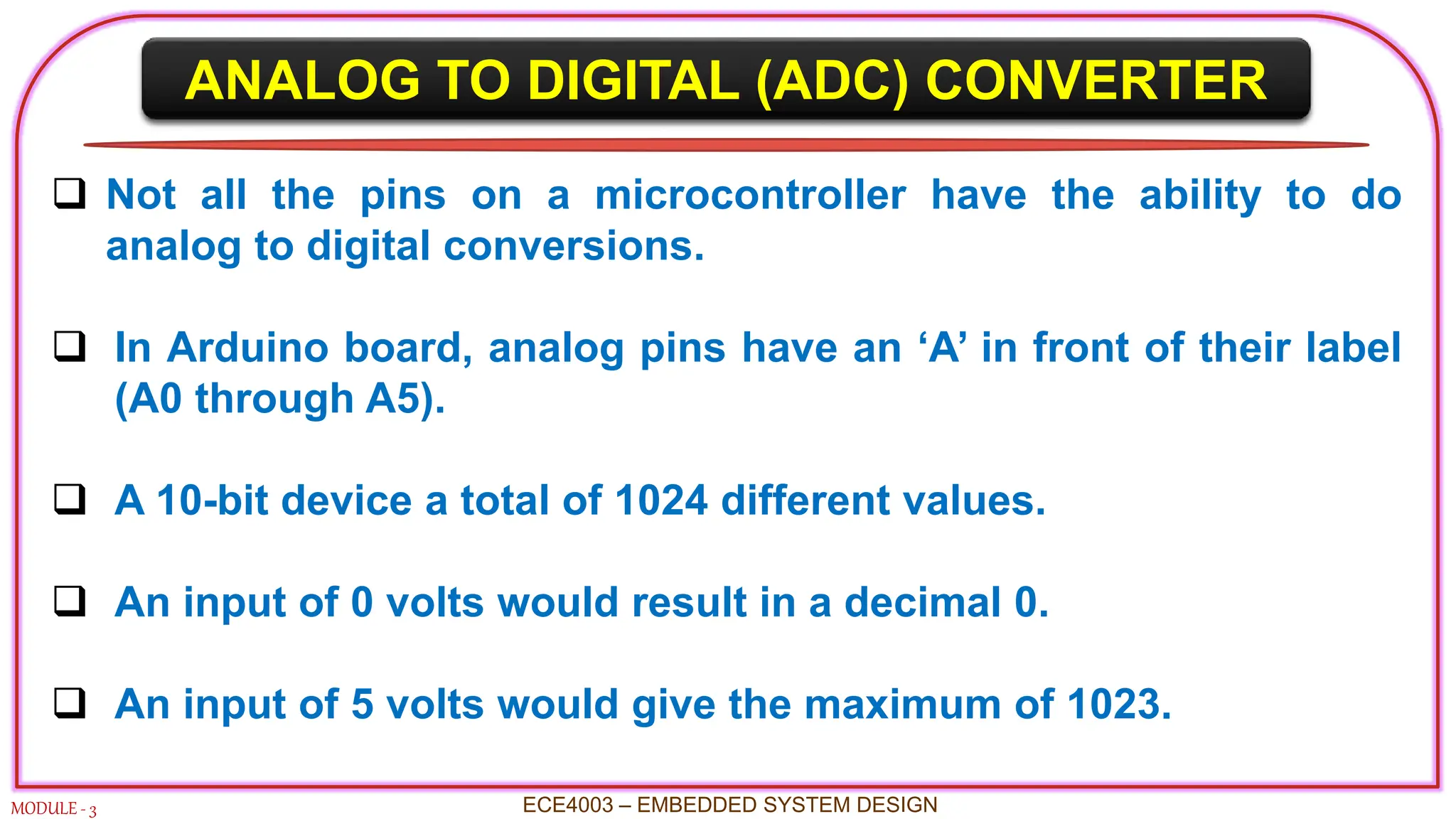
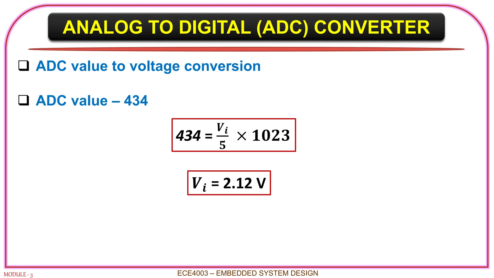
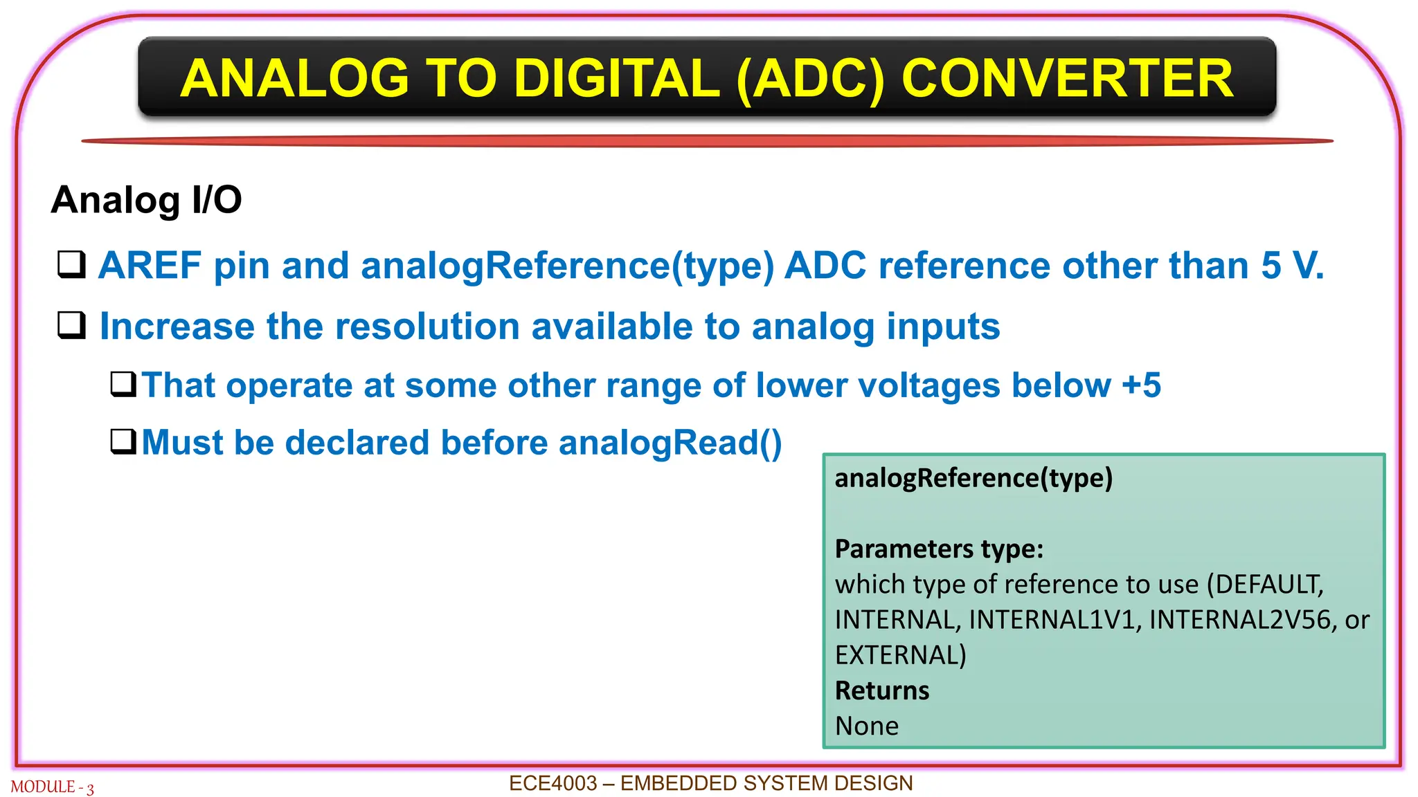
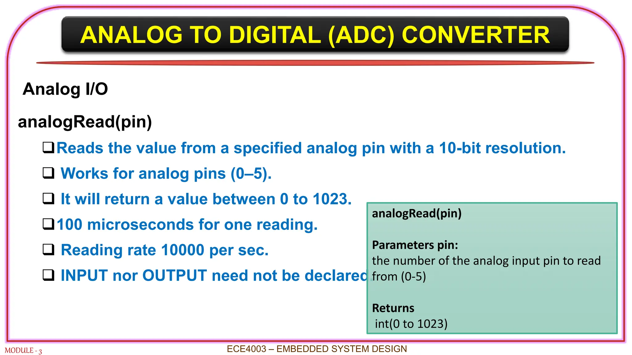
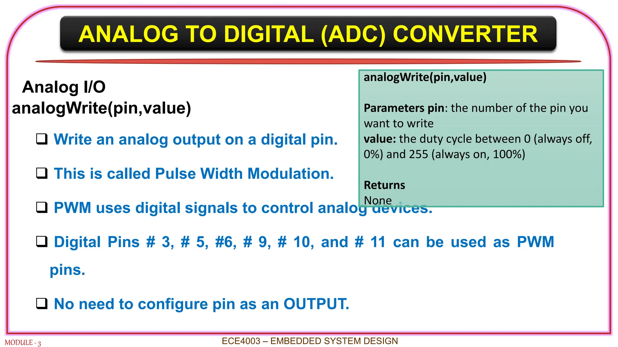
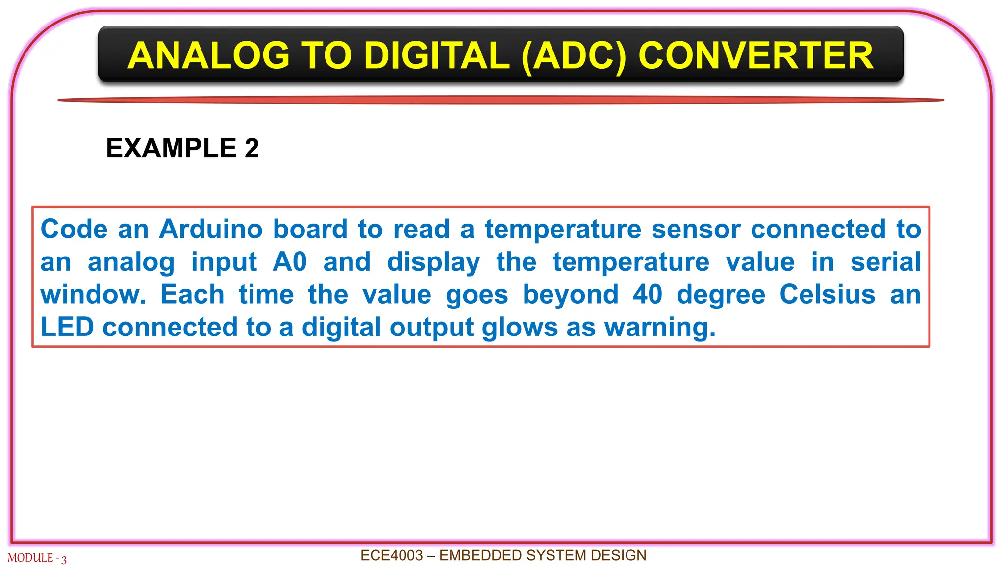
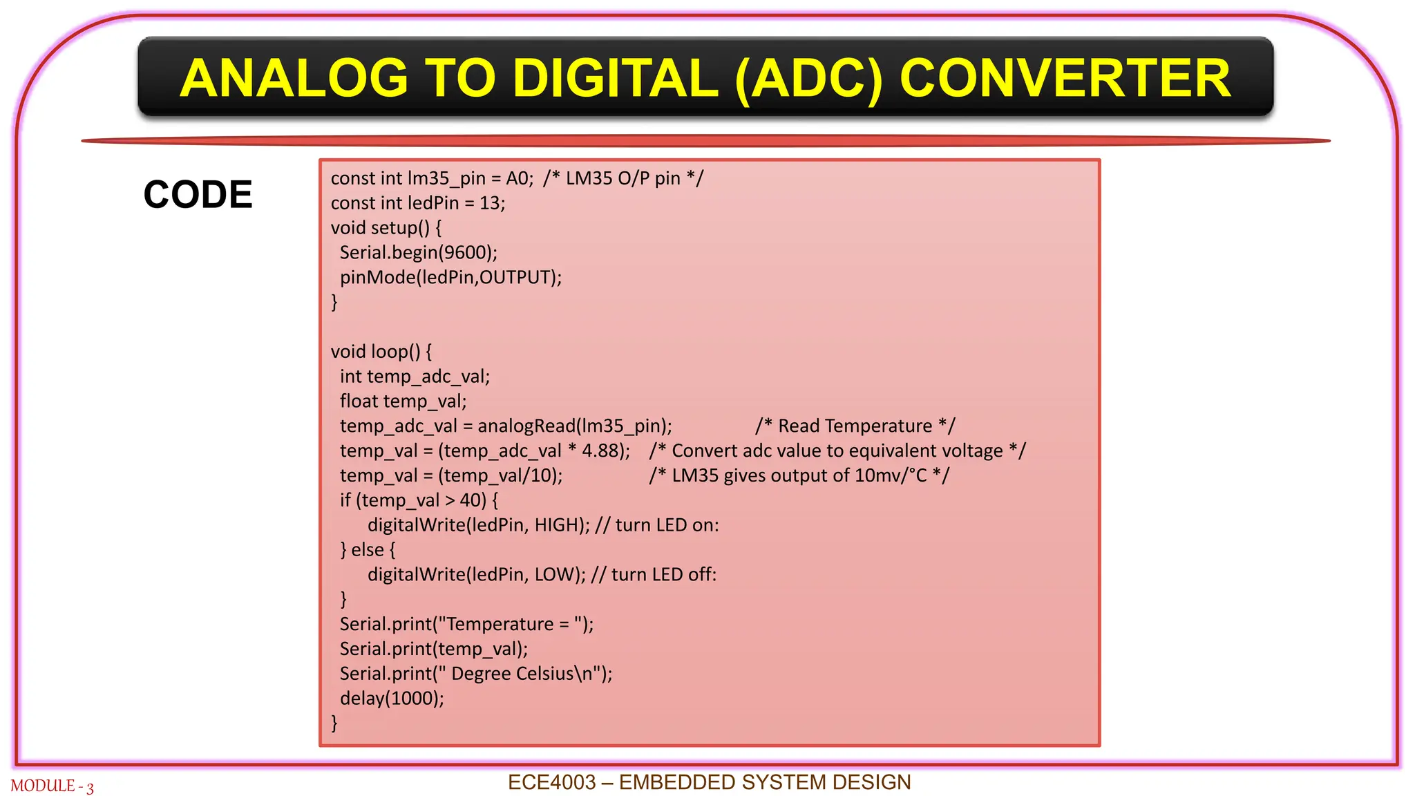
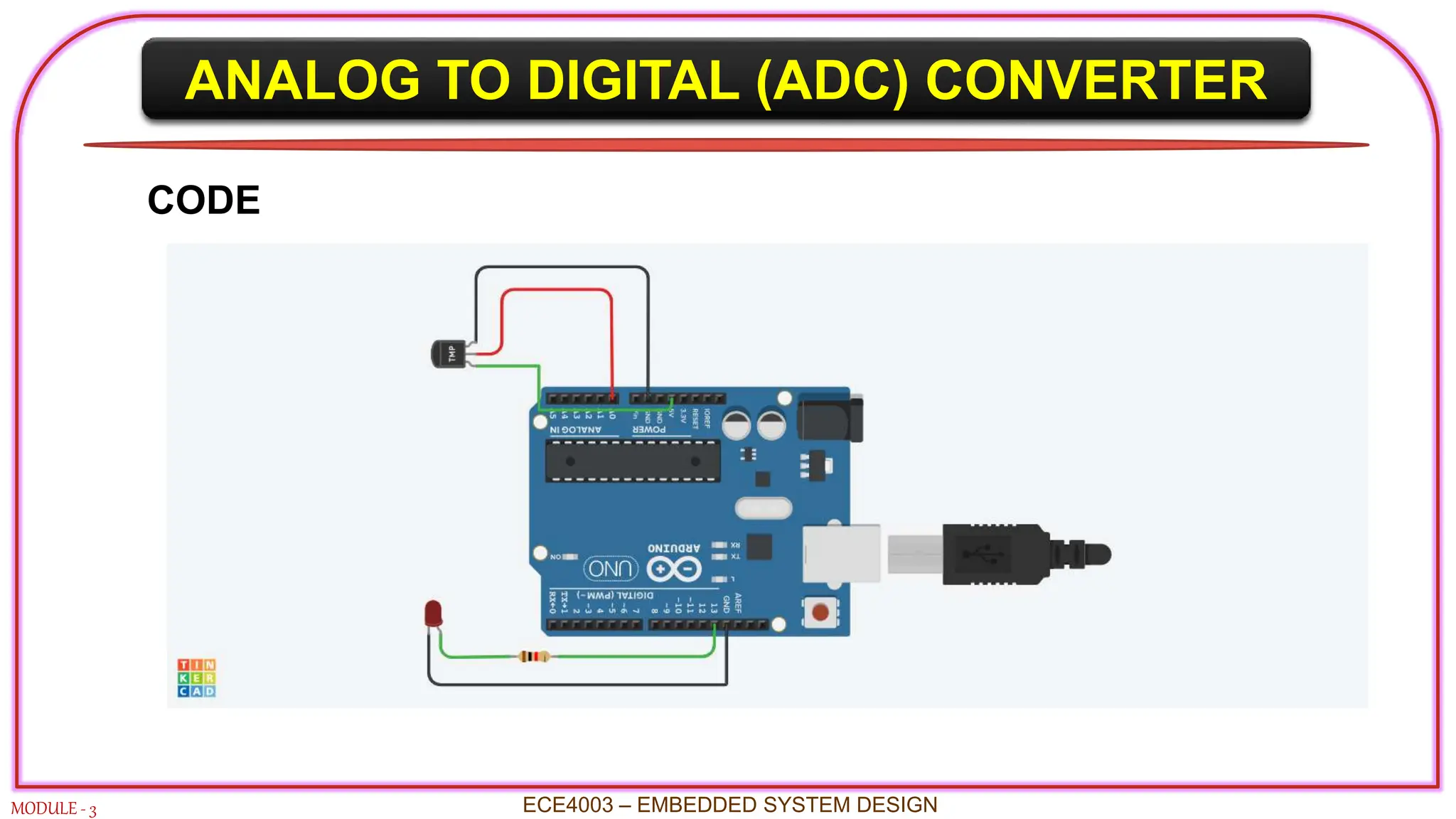
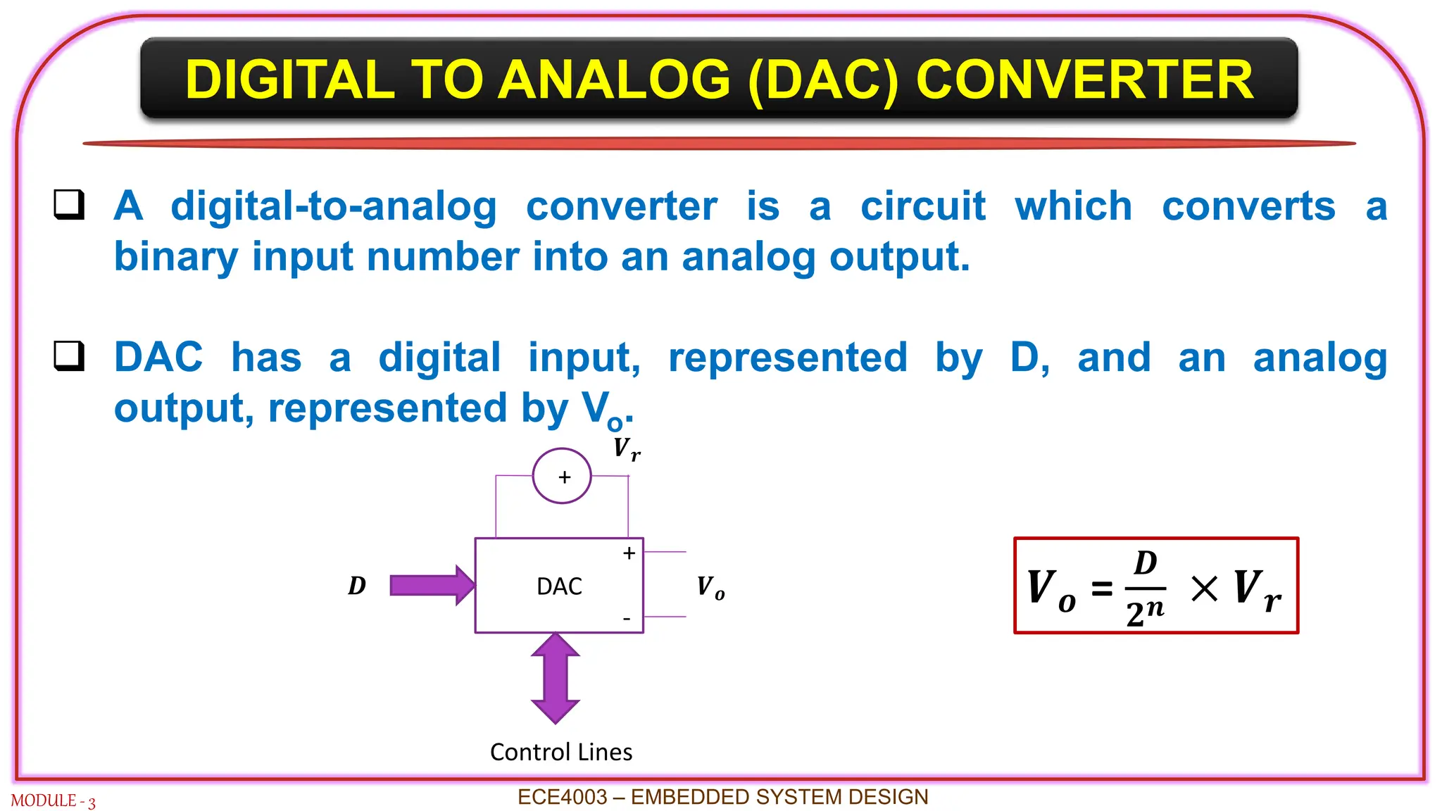
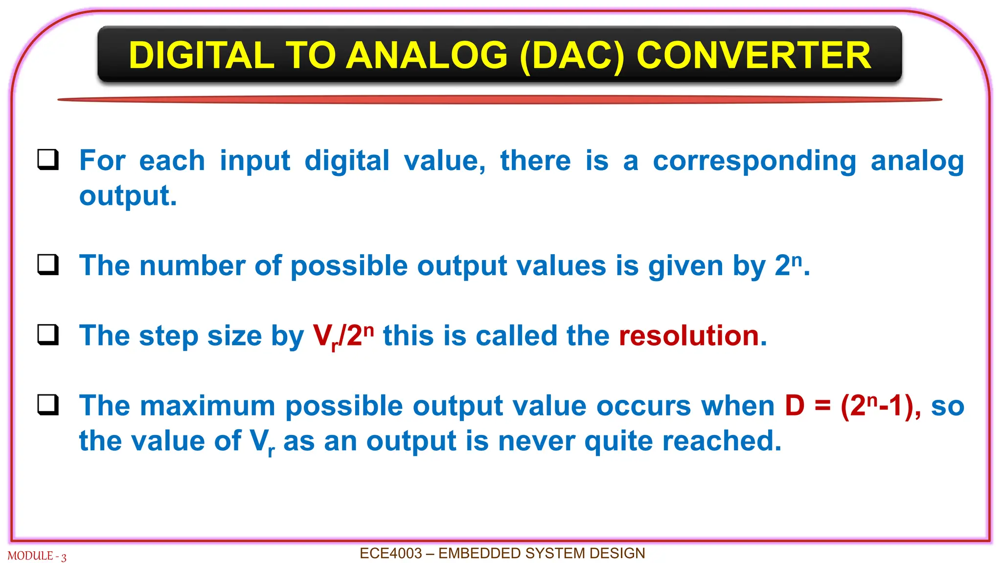
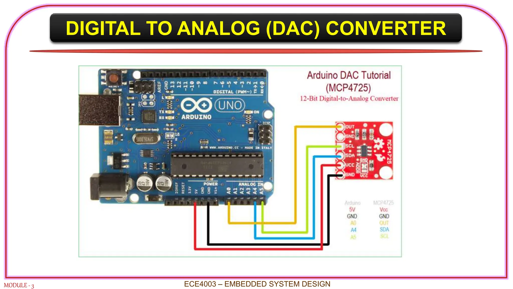
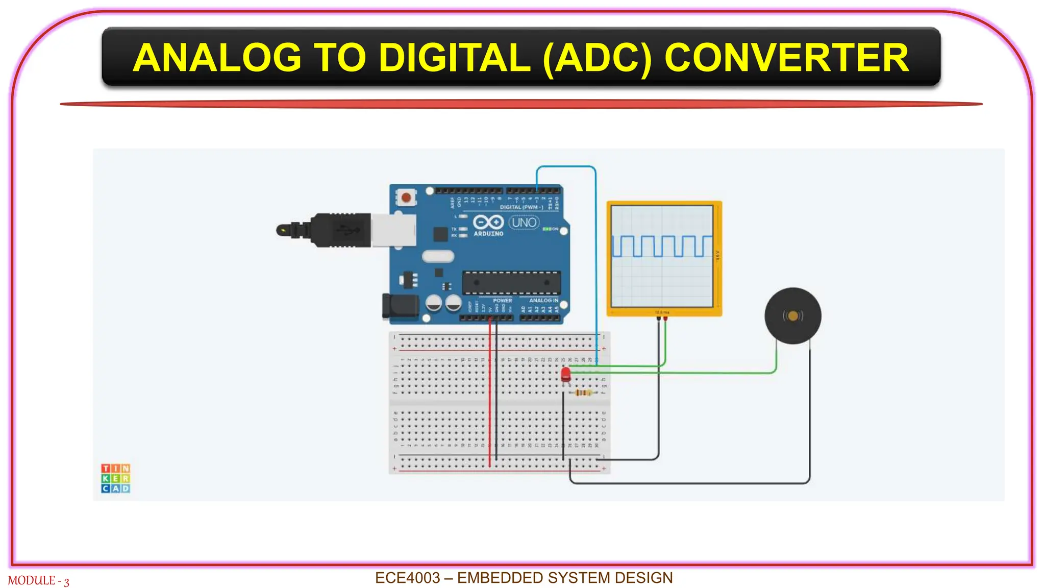
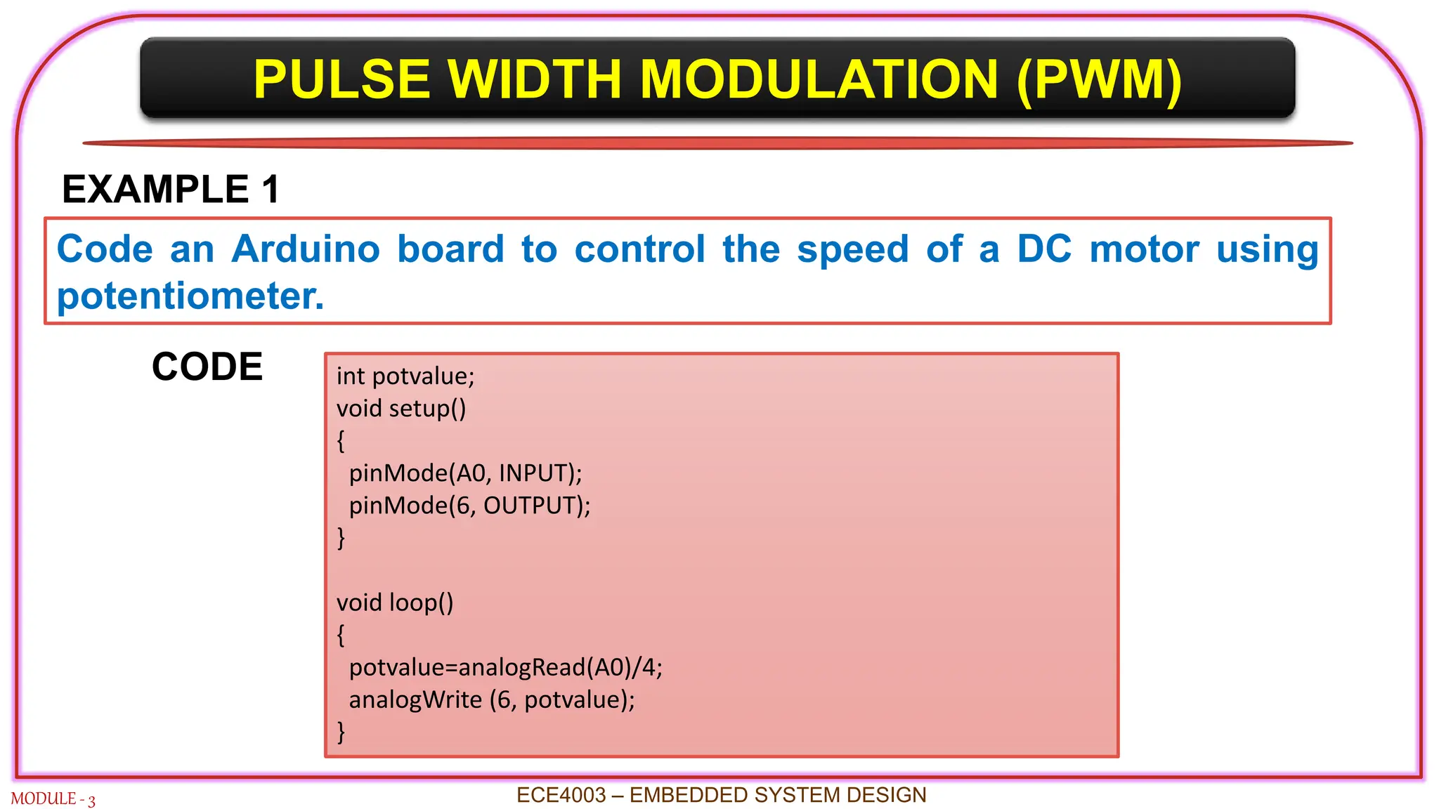
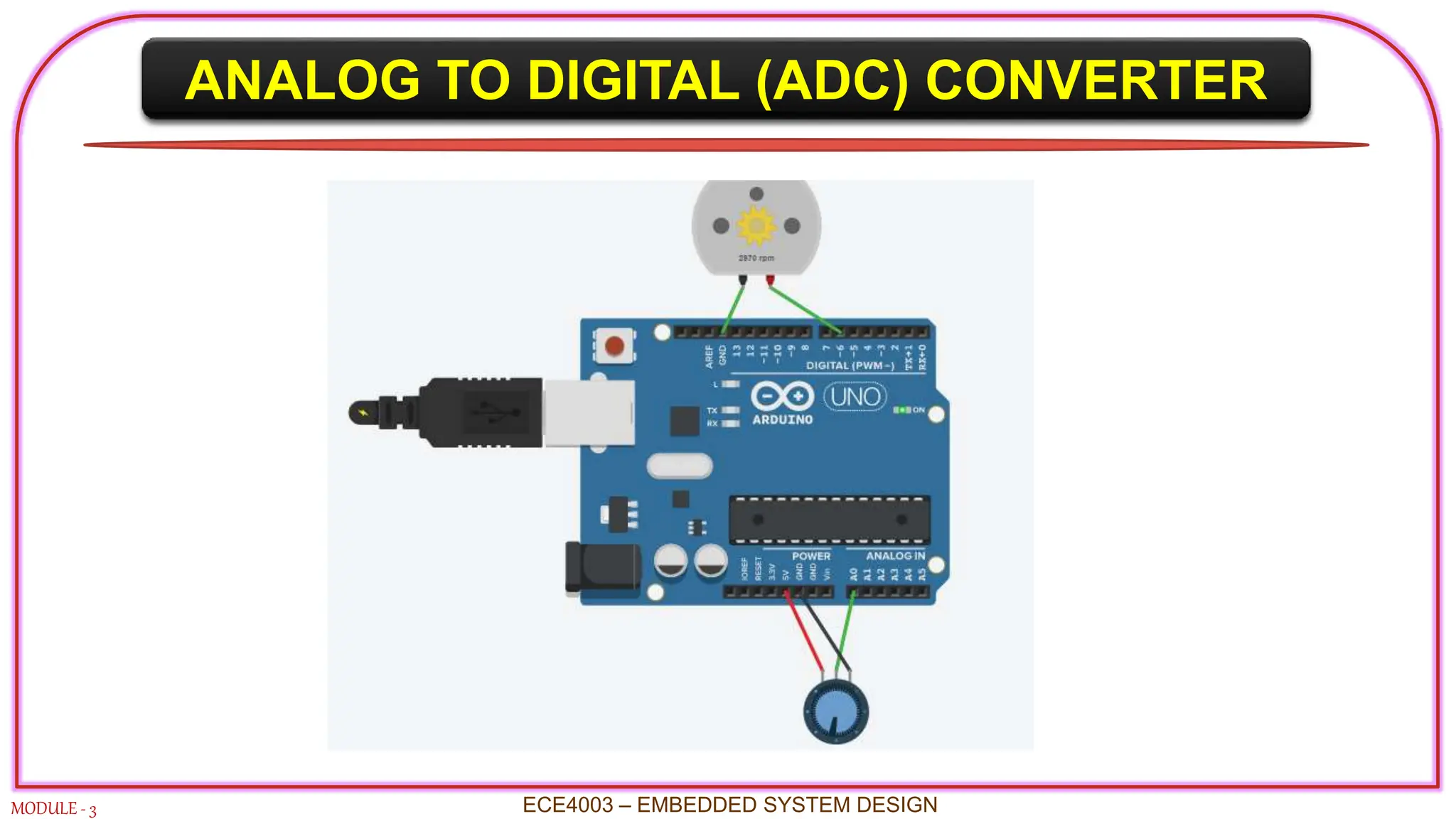
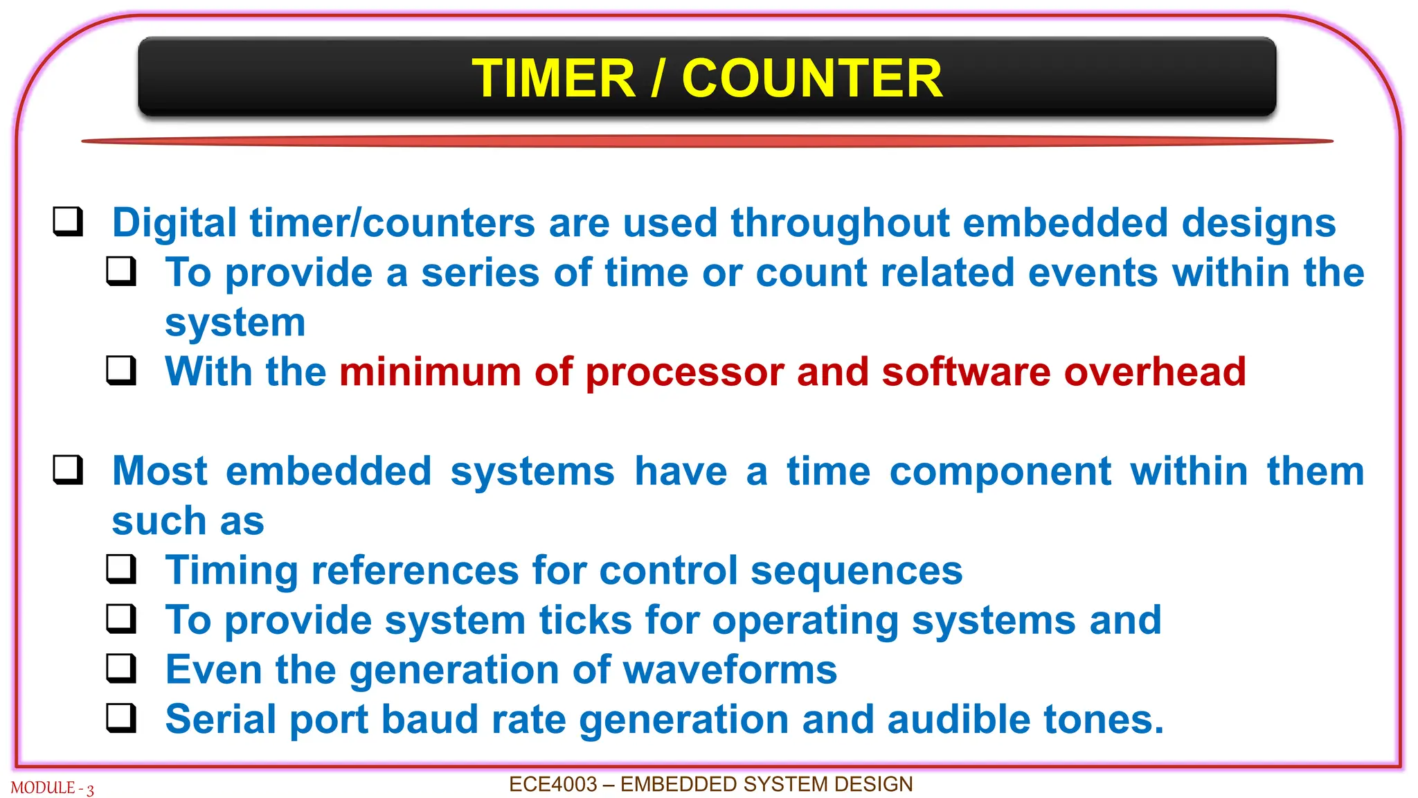
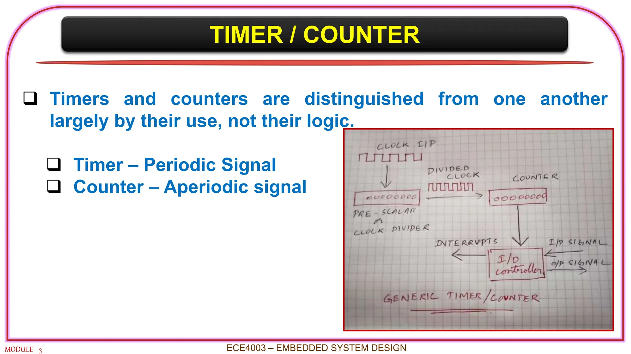
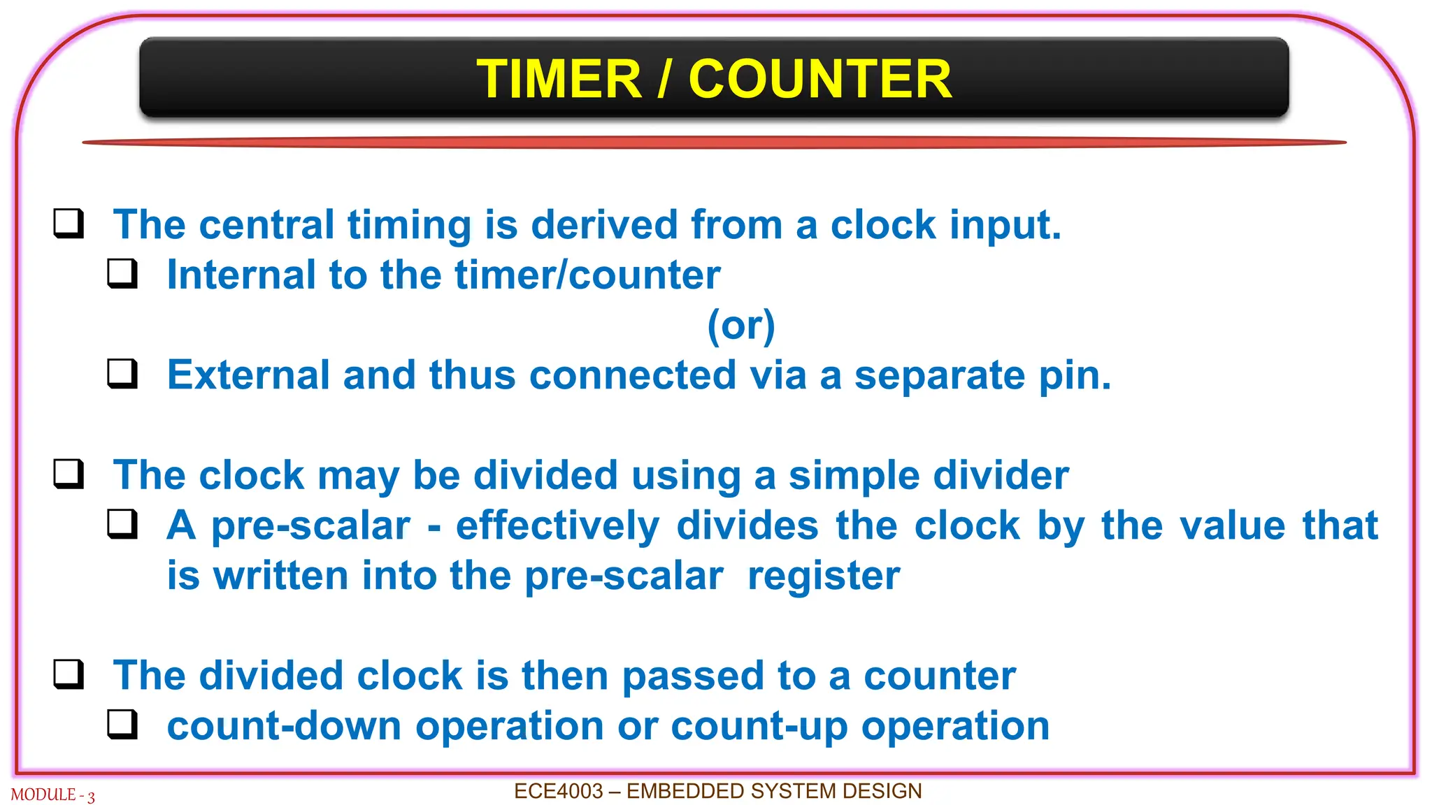
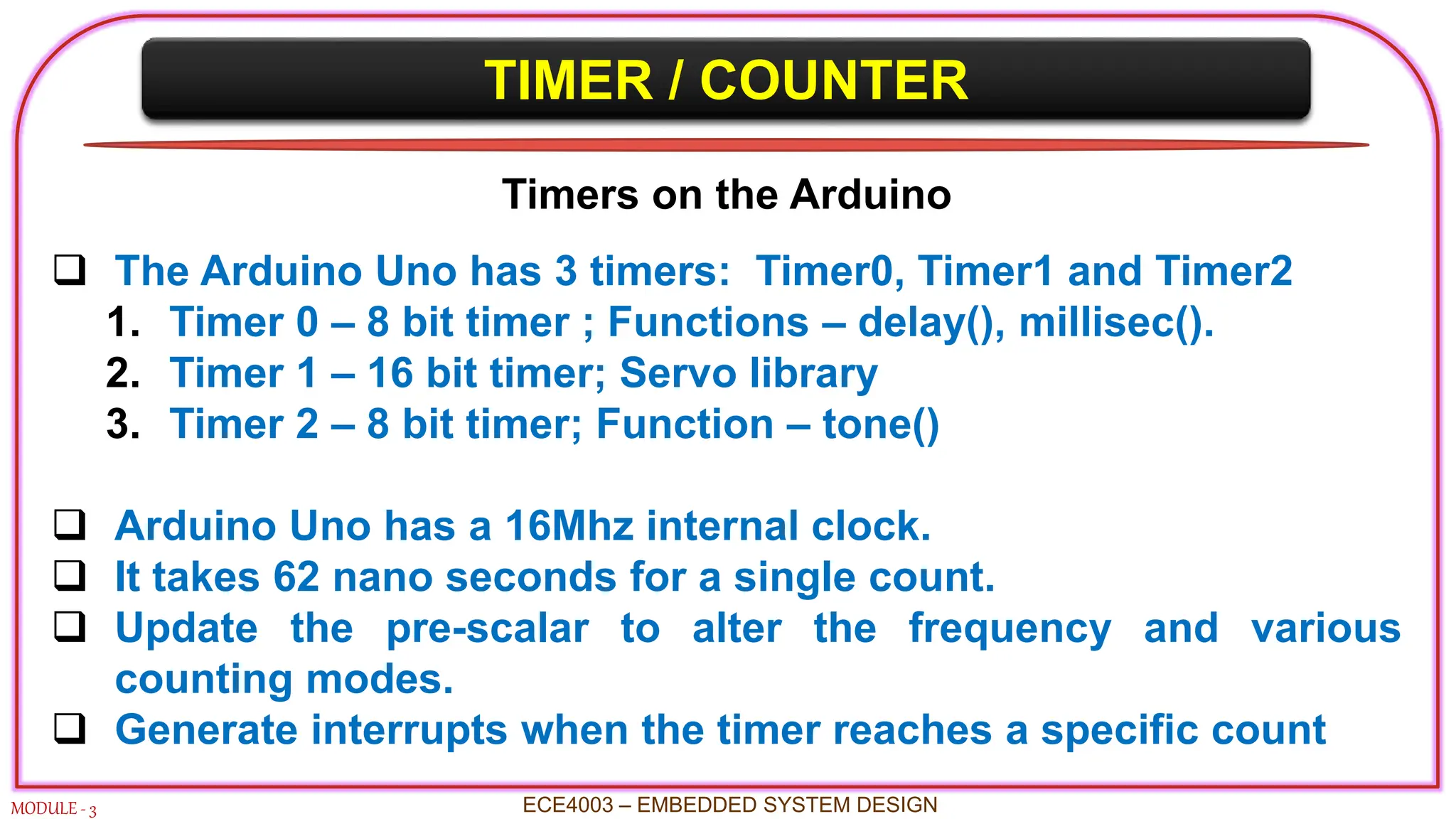
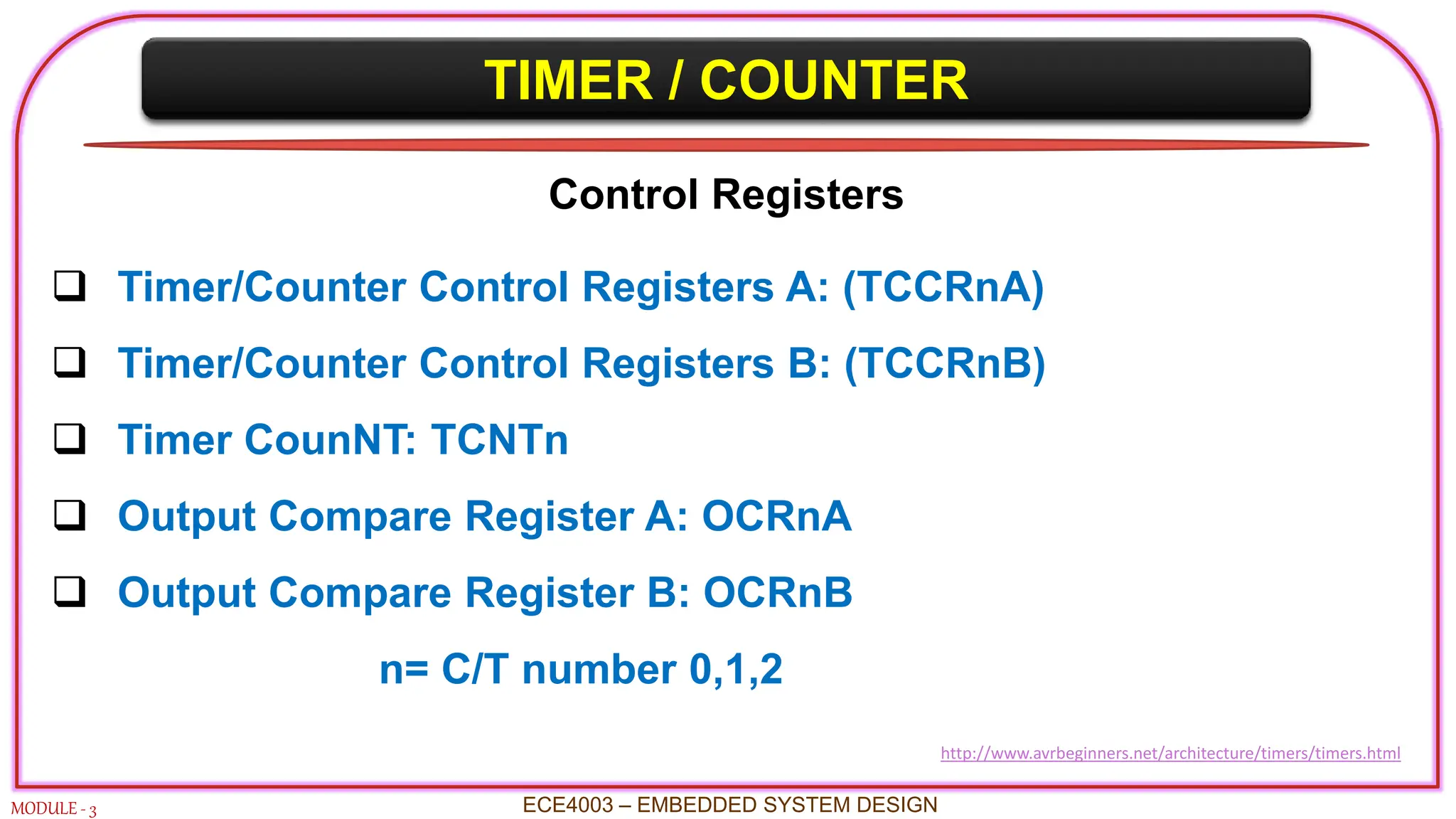
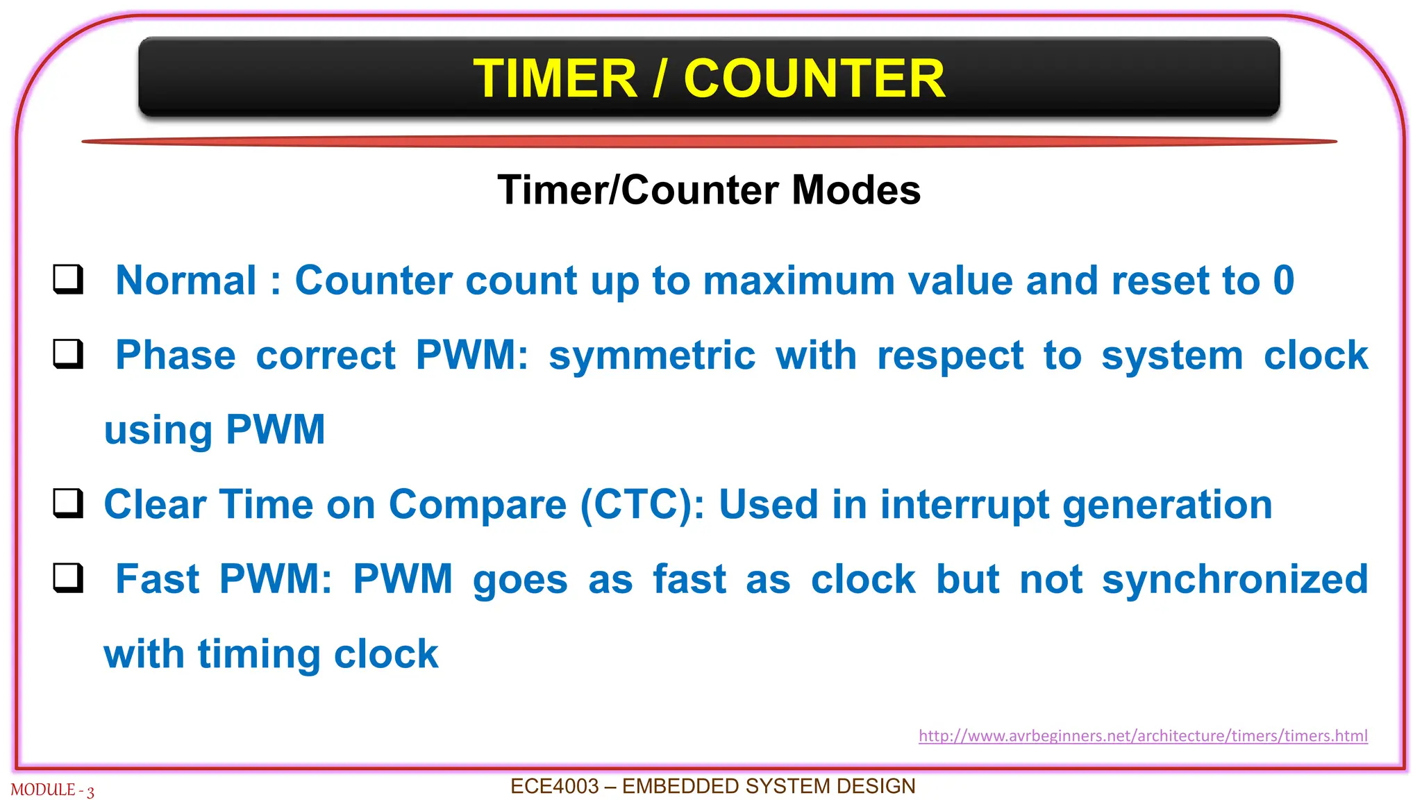
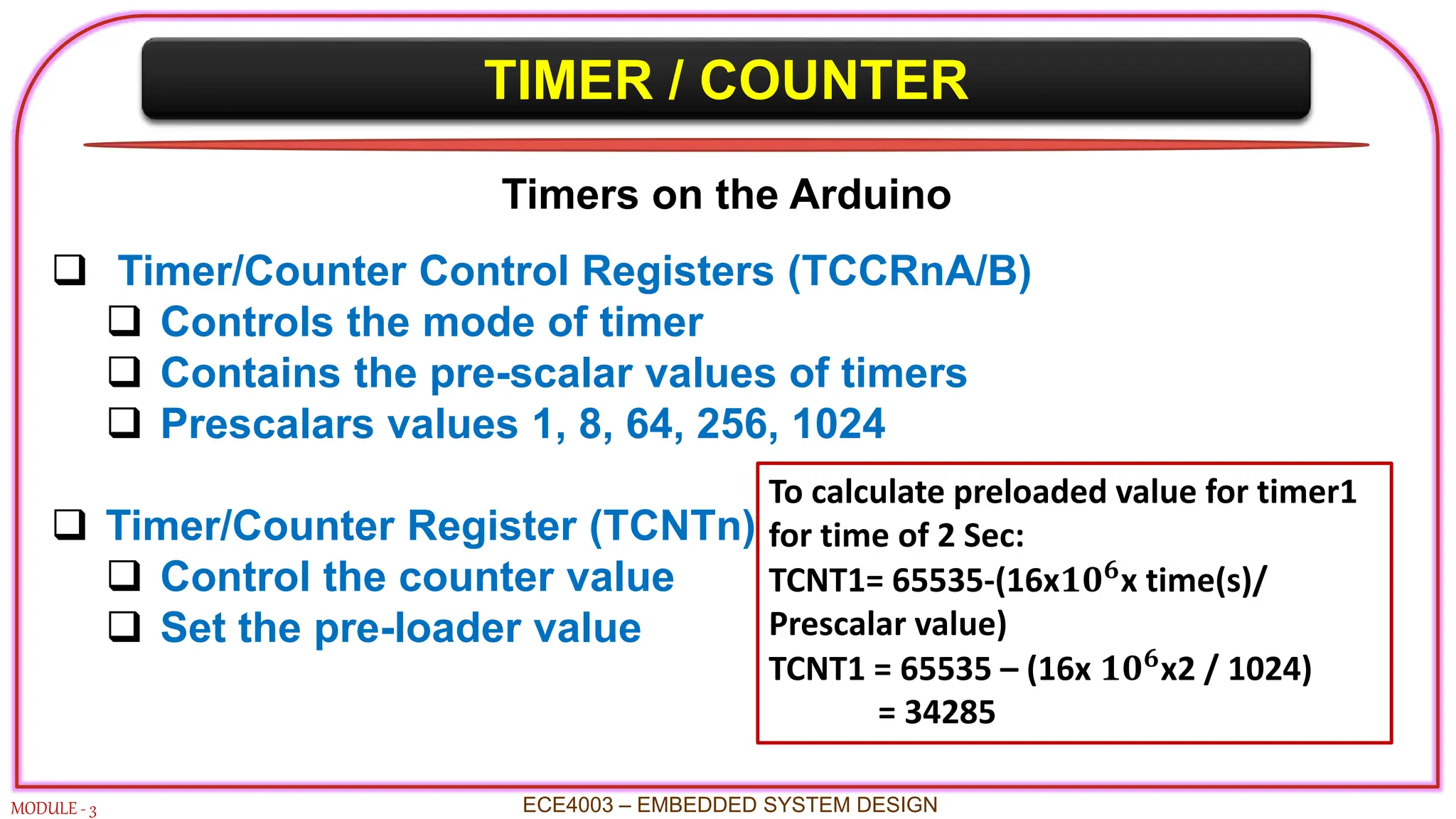
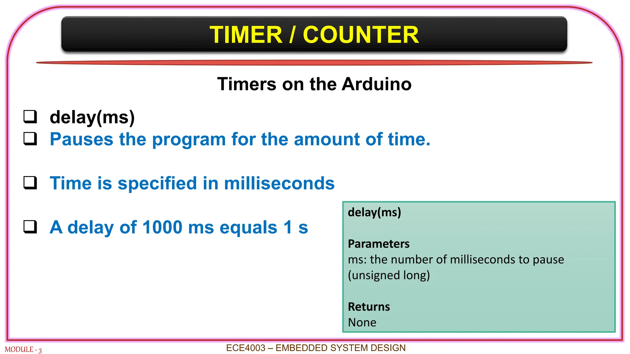
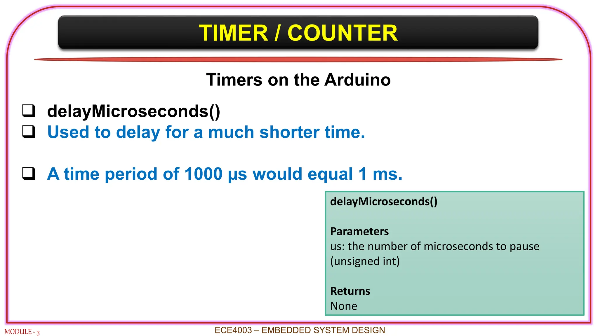
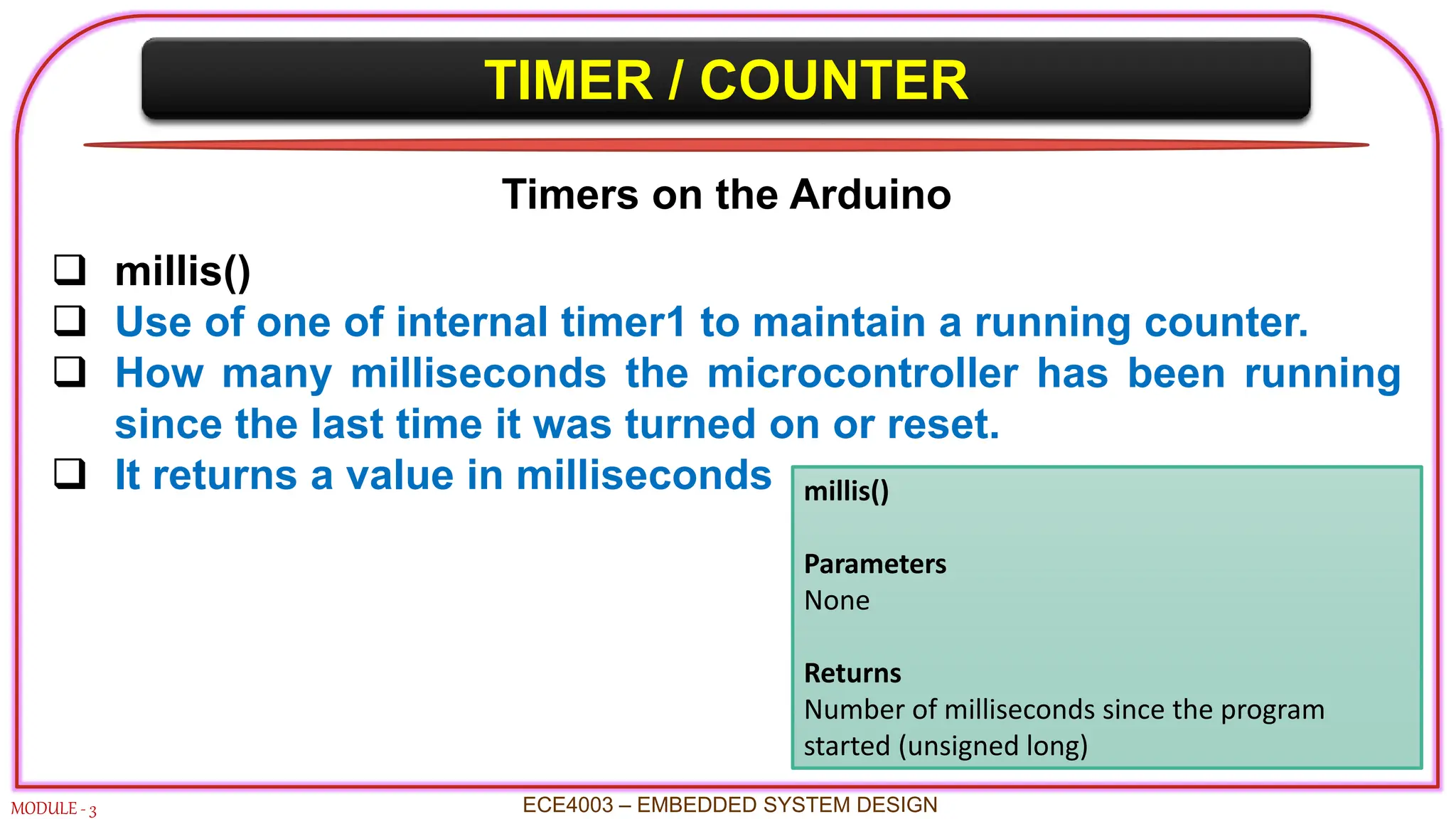
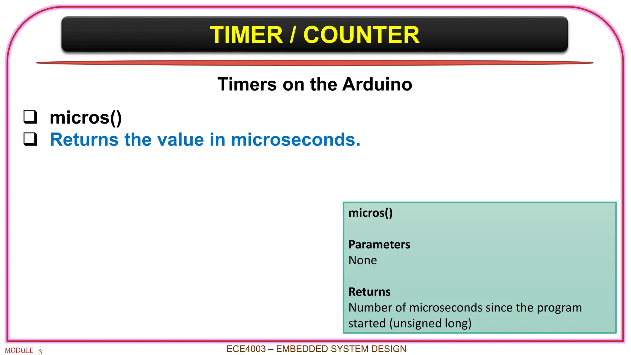
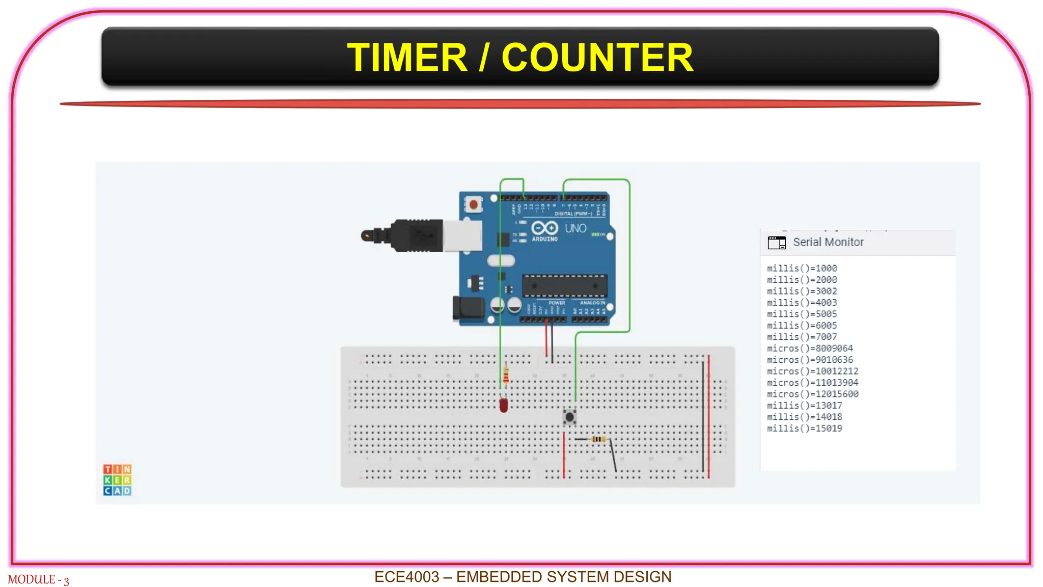
INTRODUCTION TO ARDUINO UNO
MODULE - 3 ECE4003 – EMBEDDED SYSTEM DESIGN
Features
 An open-source microcontroller board
 Microcontroller : ATmega328
 Operating Voltage : 5V
 Input Voltage (external): 6-20V (7-12 recommended)
 Digital I/O Pins : 14 (6 PWM output)
 Analog Input Pins : 6
 DC Current per I/O Pin : 40 mA
 DC Current for 3.3V Pin: 50 mA
 Flash Memory : 32 KB (0.5 KB for bootloader)
 Clock Frequency : 16 MHz
 Programming Interface : USB (ICSP)
INTRODUCTION TO ARDUINO UNO
MODULE - 3 ECE4003 – EMBEDDED SYSTEM DESIGN
Arduino Uno - Board Details
INTRODUCTION TO ARDUINO UNO
MODULE - 3 ECE4003 – EMBEDDED SYSTEM DESIGN
Arduino Uno - Pin Details
INTRODUCTION TO ATmega328
MODULE - 3 ECE4003 – EMBEDDED SYSTEM DESIGN
Features
 Instruction set Architecture : RISC
 Data bus size : 8-bit
 Address bus size : 16-bit
 Program memory (ROM) : 32 KB
 Data memory (RAM) : 2 KB
 Data memory (EEPROM) : 1 KB
 Input/output ports : 3 (B, C, D)
 General purpose registers : 32
 Timers : 3 (Timer0, 1 & 2)
 Interrupts : 26 (2 Ext. interrupts)
 ADC modules (10-bit) : 6 channels
 PWM modules : 6
 Analog comparators : 1
 Serial communication : SPI, USART, TWI(I2C)
Architecture
PROGRAMMING I/P and O/P
MODULE - 3 ECE4003 – EMBEDDED SYSTEM DESIGN
Information exchange is done by input and output devices
It may be digital or analog signal
Digital signals will be directly interfaced to CPU
Analog devices requires some converter for interfacing with CPU
All peripherals can not be always on-chip
PROGRAMMING I/P and O/P
MODULE - 3 ECE4003 – EMBEDDED SYSTEM DESIGN
Internal I/O devices
Physically silicon devices
Small size
Ex: RTC, ADCs, memory
External I/O devices
Have large size
Has bus interface
Ex: LCD, keypad, MIC
PROGRAMMING INPUT & OUTPUT
MODULE - 3 ECE4003 – EMBEDDED SYSTEM DESIGN
 CPU communicates to the device by reading and writing to the
registers.
 Data register – read and write, Status register – read only
CPU
Status
Register
Data
Register
Device
Mechanism
PROGRAMMING INPUT & OUTPUT
MODULE - 3 ECE4003 – EMBEDDED SYSTEM DESIGN
 Microcontroller programming input and output
 I/O mapped I/O
 Memory mapped I/O (widely used)
 Memory mapped I/O –
 Common address shared by both memory and I/O
 Read and write instructions to communicate with the devices
 Example: In 8051 Timer Register - MOV TMOD,#01H
PROGRAMMING INPUT & OUTPUT
MODULE - 3 ECE4003 – EMBEDDED SYSTEM DESIGN
 Busy-Wait I/O
 Checking an I/O device if it has completed the task by reading its status
register often called polling.
 Example: AGAIN: JNB TF0, AGAIN
 Interrupts
 It enables I/O devices to signal the completion or status and force
execution of a particular piece of code.
 Example: MOV IE, #82H
ANALOG TO DIGITAL (ADC) CONVERTER
MODULE - 3
 An ADC is an electronic circuit whose digital output is
proportional to its analog input.
 Effectively it “measures” the input voltage and gives a binary
output number proportional to its size.
 The list of possible analog input signals is endless, (e.g. audio
and video, medical or climatic variables)
 The ADC when operates within a larger environment, often
called a data acquisition system.
ECE4003 – EMBEDDED SYSTEM DESIGN
ANALOG TO DIGITAL (ADC) CONVERTER
MODULE - 3
 ADC conversion
Where,
 Vi is the input voltage
 Vr the reference voltage
 n the number of bits in the converter output
 D the digital output value.
 The output binary number D is an integer
 For an n-bit number can take any value from 0 to (2n - 1).
ECE4003 – EMBEDDED SYSTEM DESIGN
D =
𝑽𝒊
𝑽𝒓
× 𝟐𝒏
ANALOG TO DIGITAL (ADC) CONVERTER
MODULE - 3
 ADC has maximum and minimum permissible input values.
 Resolution is a measure of how precisely an ADC can convert
and represent a given input voltage.
 Arduino ADC is 10-bit. This leads to a resolution of 5/1024, or
4.88 mV.
ECE4003 – EMBEDDED SYSTEM DESIGN
Resolution =
𝑽𝒓
𝟐𝒏
ANALOG TO DIGITAL (ADC) CONVERTER
MODULE - 3 ECE4003 – EMBEDDED SYSTEM DESIGN
 Not all the pins on a microcontroller have the ability to do
analog to digital conversions.
 In Arduino board, analog pins have an ‘A’ in front of their label
(A0 through A5).
 A 10-bit device a total of 1024 different values.
 An input of 0 volts would result in a decimal 0.
 An input of 5 volts would give the maximum of 1023.
ANALOG TO DIGITAL (ADC) CONVERTER
MODULE - 3 ECE4003 – EMBEDDED SYSTEM DESIGN
 ADC value to voltage conversion
 ADC value – 434
434 =
𝑽𝒊
𝟓
× 𝟏𝟎𝟐𝟑
𝑽𝒊 = 2.12 V
ANALOG TO DIGITAL (ADC) CONVERTER
MODULE - 3 ECE4003 – EMBEDDED SYSTEM DESIGN
Analog I/O
 AREF pin and analogReference(type) ADC reference other than 5 V.
 Increase the resolution available to analog inputs
That operate at some other range of lower voltages below +5
Must be declared before analogRead()
analogReference(type)
Parameters type:
which type of reference to use (DEFAULT,
INTERNAL, INTERNAL1V1, INTERNAL2V56, or
EXTERNAL)
Returns
None
ANALOG TO DIGITAL (ADC) CONVERTER
MODULE - 3 ECE4003 – EMBEDDED SYSTEM DESIGN
Analog I/O
analogRead(pin)
Reads the value from a specified analog pin with a 10-bit resolution.
 Works for analog pins (0–5).
 It will return a value between 0 to 1023.
100 microseconds for one reading.
 Reading rate 10000 per sec.
 INPUT nor OUTPUT need not be declared.
analogRead(pin)
Parameters pin:
the number of the analog input pin to read
from (0-5)
Returns
int(0 to 1023)
ANALOG TO DIGITAL (ADC) CONVERTER
MODULE - 3 ECE4003 – EMBEDDED SYSTEM DESIGN
Analog I/O
analogWrite(pin,value)
 Write an analog output on a digital pin.
 This is called Pulse Width Modulation.
 PWM uses digital signals to control analog devices.
 Digital Pins # 3, # 5, #6, # 9, # 10, and # 11 can be used as PWM
pins.
 No need to configure pin as an OUTPUT.
analogWrite(pin,value)
Parameters pin: the number of the pin you
want to write
value: the duty cycle between 0 (always off,
0%) and 255 (always on, 100%)
Returns
None
ANALOG TO DIGITAL (ADC) CONVERTER
MODULE - 3 ECE4003 – EMBEDDED SYSTEM DESIGN
EXAMPLE 1
Program an Arduino board to read analog value from an analogy input
pin, convert the value into digital value and display it in a serial window.
ANALOG TO DIGITAL (ADC) CONVERTER
MODULE - 3 ECE4003 – EMBEDDED SYSTEM DESIGN
CODE int sensorValue = 0;
void setup()
{
//monitor output in serial port
Serial.begin(9600); //intitating serial communication with 9600 baud rate
}
void loop()
{
sensorValue = analogRead(A0);
//analog input is read from A0 pin
Serial.println(sensorValue);
//printing the output in serial port
delay(100); // simple delay of 100ms
}
ANALOG TO DIGITAL (ADC) CONVERTER
MODULE - 3 ECE4003 – EMBEDDED SYSTEM DESIGN
CODE
ANALOG TO DIGITAL (ADC) CONVERTER
MODULE - 3 ECE4003 – EMBEDDED SYSTEM DESIGN
EXAMPLE 2
Code an Arduino board to read a temperature sensor connected to
an analog input A0 and display the temperature value in serial
window. Each time the value goes beyond 40 degree Celsius an
LED connected to a digital output glows as warning.
ANALOG TO DIGITAL (ADC) CONVERTER
MODULE - 3 ECE4003 – EMBEDDED SYSTEM DESIGN
const int lm35_pin = A0; /* LM35 O/P pin */
const int ledPin = 13;
void setup() {
Serial.begin(9600);
pinMode(ledPin,OUTPUT);
}
void loop() {
int temp_adc_val;
float temp_val;
temp_adc_val = analogRead(lm35_pin); /* Read Temperature */
temp_val = (temp_adc_val * 4.88); /* Convert adc value to equivalent voltage */
temp_val = (temp_val/10); /* LM35 gives output of 10mv/°C */
if (temp_val > 40) {
digitalWrite(ledPin, HIGH); // turn LED on:
} else {
digitalWrite(ledPin, LOW); // turn LED off:
}
Serial.print("Temperature = ");
Serial.print(temp_val);
Serial.print(" Degree Celsiusn");
delay(1000);
}
CODE
ANALOG TO DIGITAL (ADC) CONVERTER
MODULE - 3 ECE4003 – EMBEDDED SYSTEM DESIGN
CODE
DIGITAL TO ANALOG (DAC) CONVERTER
MODULE - 3
 A digital-to-analog converter is a circuit which converts a
binary input number into an analog output.
 DAC has a digital input, represented by D, and an analog
output, represented by Vo.
ECE4003 – EMBEDDED SYSTEM DESIGN
𝑽𝒐 =
𝑫
𝟐𝒏 × 𝑽𝒓
DAC
+
𝑽𝒐
+
-
𝑽𝒓
𝑫
Control Lines
DIGITAL TO ANALOG (DAC) CONVERTER
MODULE - 3
 For each input digital value, there is a corresponding analog
output.
 The number of possible output values is given by 2n.
 The step size by Vr/2n this is called the resolution.
 The maximum possible output value occurs when D = (2n-1), so
the value of Vr as an output is never quite reached.
ECE4003 – EMBEDDED SYSTEM DESIGN
DIGITAL TO ANALOG (DAC) CONVERTER
MODULE - 3 ECE4003 – EMBEDDED SYSTEM DESIGN
ANALOG TO DIGITAL (ADC) CONVERTER
MODULE - 3 ECE4003 – EMBEDDED SYSTEM DESIGN
PULSE WIDTH MODULATION (PWM)
MODULE - 3 ECE4003 – EMBEDDED SYSTEM DESIGN
EXAMPLE 1
Code an Arduino board to control the speed of a DC motor using
potentiometer.
int potvalue;
void setup()
{
pinMode(A0, INPUT);
pinMode(6, OUTPUT);
}
void loop()
{
potvalue=analogRead(A0)/4;
analogWrite (6, potvalue);
}
CODE
ANALOG TO DIGITAL (ADC) CONVERTER
MODULE - 3 ECE4003 – EMBEDDED SYSTEM DESIGN
TIMER / COUNTER
MODULE - 3
 Digital timer/counters are used throughout embedded designs
 To provide a series of time or count related events within the
system
 With the minimum of processor and software overhead
 Most embedded systems have a time component within them
such as
 Timing references for control sequences
 To provide system ticks for operating systems and
 Even the generation of waveforms
 Serial port baud rate generation and audible tones.
ECE4003 – EMBEDDED SYSTEM DESIGN
TIMER / COUNTER
MODULE - 3
 Timers and counters are distinguished from one another
largely by their use, not their logic.
 Timer – Periodic Signal
 Counter – Aperiodic signal
ECE4003 – EMBEDDED SYSTEM DESIGN
TIMER / COUNTER
MODULE - 3
 The central timing is derived from a clock input.
 Internal to the timer/counter
(or)
 External and thus connected via a separate pin.
 The clock may be divided using a simple divider
 A pre-scalar - effectively divides the clock by the value that
is written into the pre-scalar register
 The divided clock is then passed to a counter
 count-down operation or count-up operation
ECE4003 – EMBEDDED SYSTEM DESIGN
TIMER / COUNTER
MODULE - 3
 When a zero count is reached, an event occurs.
 such as an interrupt of an external line changing state.
 The final block is an I/O control block
 It generates interrupts
 Can control the counter based on external signals
ECE4003 – EMBEDDED SYSTEM DESIGN
TIMER / COUNTER
MODULE - 3
Timers on the Arduino
 The Arduino Uno has 3 timers: Timer0, Timer1 and Timer2
1. Timer 0 – 8 bit timer ; Functions – delay(), millisec().
2. Timer 1 – 16 bit timer; Servo library
3. Timer 2 – 8 bit timer; Function – tone()
 Arduino Uno has a 16Mhz internal clock.
 It takes 62 nano seconds for a single count.
 Update the pre-scalar to alter the frequency and various
counting modes.
 Generate interrupts when the timer reaches a specific count
ECE4003 – EMBEDDED SYSTEM DESIGN
TIMER / COUNTER
MODULE - 3
Control Registers
 Timer/Counter Control Registers A: (TCCRnA)
 Timer/Counter Control Registers B: (TCCRnB)
 Timer CounNT: TCNTn
 Output Compare Register A: OCRnA
 Output Compare Register B: OCRnB
n= C/T number 0,1,2
ECE4003 – EMBEDDED SYSTEM DESIGN
http://www.avrbeginners.net/architecture/timers/timers.html
TIMER / COUNTER
MODULE - 3
Timer/Counter Modes
 Normal : Counter count up to maximum value and reset to 0
 Phase correct PWM: symmetric with respect to system clock
using PWM
 Clear Time on Compare (CTC): Used in interrupt generation
 Fast PWM: PWM goes as fast as clock but not synchronized
with timing clock
ECE4003 – EMBEDDED SYSTEM DESIGN
http://www.avrbeginners.net/architecture/timers/timers.html
TIMER / COUNTER
MODULE - 3
Timers on the Arduino
 Timer/Counter Control Registers (TCCRnA/B)
 Controls the mode of timer
 Contains the pre-scalar values of timers
 Prescalars values 1, 8, 64, 256, 1024
 Timer/Counter Register (TCNTn)
 Control the counter value
 Set the pre-loader value
ECE4003 – EMBEDDED SYSTEM DESIGN
To calculate preloaded value for timer1
for time of 2 Sec:
TCNT1= 65535-(16x𝟏𝟎𝟔x time(s)/
Prescalar value)
TCNT1 = 65535 – (16x 𝟏𝟎𝟔
x2 / 1024)
= 34285
TIMER / COUNTER
MODULE - 3 ECE4003 – EMBEDDED SYSTEM DESIGN
Timers on the Arduino
 delay(ms)
 Pauses the program for the amount of time.
 Time is specified in milliseconds
 A delay of 1000 ms equals 1 s
delay(ms)
Parameters
ms: the number of milliseconds to pause
(unsigned long)
Returns
None
TIMER / COUNTER
MODULE - 3 ECE4003 – EMBEDDED SYSTEM DESIGN
Timers on the Arduino
 delayMicroseconds()
 Used to delay for a much shorter time.
 A time period of 1000 µs would equal 1 ms.
delayMicroseconds()
Parameters
us: the number of microseconds to pause
(unsigned int)
Returns
None
TIMER / COUNTER
MODULE - 3 ECE4003 – EMBEDDED SYSTEM DESIGN
Timers on the Arduino
 millis()
 Use of one of internal timer1 to maintain a running counter.
 How many milliseconds the microcontroller has been running
since the last time it was turned on or reset.
 It returns a value in milliseconds millis()
Parameters
None
Returns
Number of milliseconds since the program
started (unsigned long)
TIMER / COUNTER
MODULE - 3 ECE4003 – EMBEDDED SYSTEM DESIGN
Timers on the Arduino
 micros()
 Returns the value in microseconds.
micros()
Parameters
None
Returns
Number of microseconds since the program
started (unsigned long)
TIMER / COUNTER
MODULE - 3 ECE4003 – EMBEDDED SYSTEM DESIGN
EXAMPLE
Code an Arduino board to read a pushbutton connected to a digital
input to display millis() when ON and display micros() when OFF.
Blink an LED connected to a digital output with 500 ms delay.
TIMER / COUNTER
MODULE - 3 ECE4003 – EMBEDDED SYSTEM DESIGN
#define LED 13
int buttonState = 0;
void setup() {
Serial.begin(9600);
pinMode(LED, OUTPUT);
pinMode(7, INPUT);}
void loop() {
digitalWrite(LED, HIGH);
delay(500);
digitalWrite(LED, LOW);
delay(500);
buttonState = digitalRead(7);
if(buttonState==LOW) {
Serial.write("micros()=");
Serial.println(micros());
}else {
Serial.write("millis()=");
Serial.println(millis());
}}
CODE
TIMER / COUNTER
MODULE - 3 ECE4003 – EMBEDDED SYSTEM DESIGN

Embedded systems optimization memory requirments.pptx

  • 2.
    INTRODUCTION TO ARDUINOUNO MODULE - 3 ECE4003 – EMBEDDED SYSTEM DESIGN Features  An open-source microcontroller board  Microcontroller : ATmega328  Operating Voltage : 5V  Input Voltage (external): 6-20V (7-12 recommended)  Digital I/O Pins : 14 (6 PWM output)  Analog Input Pins : 6  DC Current per I/O Pin : 40 mA  DC Current for 3.3V Pin: 50 mA  Flash Memory : 32 KB (0.5 KB for bootloader)  Clock Frequency : 16 MHz  Programming Interface : USB (ICSP)
  • 3.
    INTRODUCTION TO ARDUINOUNO MODULE - 3 ECE4003 – EMBEDDED SYSTEM DESIGN Arduino Uno - Board Details
  • 4.
    INTRODUCTION TO ARDUINOUNO MODULE - 3 ECE4003 – EMBEDDED SYSTEM DESIGN Arduino Uno - Pin Details
  • 5.
    INTRODUCTION TO ATmega328 MODULE- 3 ECE4003 – EMBEDDED SYSTEM DESIGN Features  Instruction set Architecture : RISC  Data bus size : 8-bit  Address bus size : 16-bit  Program memory (ROM) : 32 KB  Data memory (RAM) : 2 KB  Data memory (EEPROM) : 1 KB  Input/output ports : 3 (B, C, D)  General purpose registers : 32  Timers : 3 (Timer0, 1 & 2)  Interrupts : 26 (2 Ext. interrupts)  ADC modules (10-bit) : 6 channels  PWM modules : 6  Analog comparators : 1  Serial communication : SPI, USART, TWI(I2C) Architecture
  • 6.
    PROGRAMMING I/P andO/P MODULE - 3 ECE4003 – EMBEDDED SYSTEM DESIGN Information exchange is done by input and output devices It may be digital or analog signal Digital signals will be directly interfaced to CPU Analog devices requires some converter for interfacing with CPU All peripherals can not be always on-chip
  • 7.
    PROGRAMMING I/P andO/P MODULE - 3 ECE4003 – EMBEDDED SYSTEM DESIGN Internal I/O devices Physically silicon devices Small size Ex: RTC, ADCs, memory External I/O devices Have large size Has bus interface Ex: LCD, keypad, MIC
  • 8.
    PROGRAMMING INPUT &OUTPUT MODULE - 3 ECE4003 – EMBEDDED SYSTEM DESIGN  CPU communicates to the device by reading and writing to the registers.  Data register – read and write, Status register – read only CPU Status Register Data Register Device Mechanism
  • 9.
    PROGRAMMING INPUT &OUTPUT MODULE - 3 ECE4003 – EMBEDDED SYSTEM DESIGN  Microcontroller programming input and output  I/O mapped I/O  Memory mapped I/O (widely used)  Memory mapped I/O –  Common address shared by both memory and I/O  Read and write instructions to communicate with the devices  Example: In 8051 Timer Register - MOV TMOD,#01H
  • 10.
    PROGRAMMING INPUT &OUTPUT MODULE - 3 ECE4003 – EMBEDDED SYSTEM DESIGN  Busy-Wait I/O  Checking an I/O device if it has completed the task by reading its status register often called polling.  Example: AGAIN: JNB TF0, AGAIN  Interrupts  It enables I/O devices to signal the completion or status and force execution of a particular piece of code.  Example: MOV IE, #82H
  • 12.
    ANALOG TO DIGITAL(ADC) CONVERTER MODULE - 3  An ADC is an electronic circuit whose digital output is proportional to its analog input.  Effectively it “measures” the input voltage and gives a binary output number proportional to its size.  The list of possible analog input signals is endless, (e.g. audio and video, medical or climatic variables)  The ADC when operates within a larger environment, often called a data acquisition system. ECE4003 – EMBEDDED SYSTEM DESIGN
  • 13.
    ANALOG TO DIGITAL(ADC) CONVERTER MODULE - 3  ADC conversion Where,  Vi is the input voltage  Vr the reference voltage  n the number of bits in the converter output  D the digital output value.  The output binary number D is an integer  For an n-bit number can take any value from 0 to (2n - 1). ECE4003 – EMBEDDED SYSTEM DESIGN D = 𝑽𝒊 𝑽𝒓 × 𝟐𝒏
  • 14.
    ANALOG TO DIGITAL(ADC) CONVERTER MODULE - 3  ADC has maximum and minimum permissible input values.  Resolution is a measure of how precisely an ADC can convert and represent a given input voltage.  Arduino ADC is 10-bit. This leads to a resolution of 5/1024, or 4.88 mV. ECE4003 – EMBEDDED SYSTEM DESIGN Resolution = 𝑽𝒓 𝟐𝒏
  • 15.
    ANALOG TO DIGITAL(ADC) CONVERTER MODULE - 3 ECE4003 – EMBEDDED SYSTEM DESIGN  Not all the pins on a microcontroller have the ability to do analog to digital conversions.  In Arduino board, analog pins have an ‘A’ in front of their label (A0 through A5).  A 10-bit device a total of 1024 different values.  An input of 0 volts would result in a decimal 0.  An input of 5 volts would give the maximum of 1023.
  • 16.
    ANALOG TO DIGITAL(ADC) CONVERTER MODULE - 3 ECE4003 – EMBEDDED SYSTEM DESIGN  ADC value to voltage conversion  ADC value – 434 434 = 𝑽𝒊 𝟓 × 𝟏𝟎𝟐𝟑 𝑽𝒊 = 2.12 V
  • 17.
    ANALOG TO DIGITAL(ADC) CONVERTER MODULE - 3 ECE4003 – EMBEDDED SYSTEM DESIGN Analog I/O  AREF pin and analogReference(type) ADC reference other than 5 V.  Increase the resolution available to analog inputs That operate at some other range of lower voltages below +5 Must be declared before analogRead() analogReference(type) Parameters type: which type of reference to use (DEFAULT, INTERNAL, INTERNAL1V1, INTERNAL2V56, or EXTERNAL) Returns None
  • 18.
    ANALOG TO DIGITAL(ADC) CONVERTER MODULE - 3 ECE4003 – EMBEDDED SYSTEM DESIGN Analog I/O analogRead(pin) Reads the value from a specified analog pin with a 10-bit resolution.  Works for analog pins (0–5).  It will return a value between 0 to 1023. 100 microseconds for one reading.  Reading rate 10000 per sec.  INPUT nor OUTPUT need not be declared. analogRead(pin) Parameters pin: the number of the analog input pin to read from (0-5) Returns int(0 to 1023)
  • 19.
    ANALOG TO DIGITAL(ADC) CONVERTER MODULE - 3 ECE4003 – EMBEDDED SYSTEM DESIGN Analog I/O analogWrite(pin,value)  Write an analog output on a digital pin.  This is called Pulse Width Modulation.  PWM uses digital signals to control analog devices.  Digital Pins # 3, # 5, #6, # 9, # 10, and # 11 can be used as PWM pins.  No need to configure pin as an OUTPUT. analogWrite(pin,value) Parameters pin: the number of the pin you want to write value: the duty cycle between 0 (always off, 0%) and 255 (always on, 100%) Returns None
  • 20.
    ANALOG TO DIGITAL(ADC) CONVERTER MODULE - 3 ECE4003 – EMBEDDED SYSTEM DESIGN EXAMPLE 1 Program an Arduino board to read analog value from an analogy input pin, convert the value into digital value and display it in a serial window.
  • 21.
    ANALOG TO DIGITAL(ADC) CONVERTER MODULE - 3 ECE4003 – EMBEDDED SYSTEM DESIGN CODE int sensorValue = 0; void setup() { //monitor output in serial port Serial.begin(9600); //intitating serial communication with 9600 baud rate } void loop() { sensorValue = analogRead(A0); //analog input is read from A0 pin Serial.println(sensorValue); //printing the output in serial port delay(100); // simple delay of 100ms }
  • 22.
    ANALOG TO DIGITAL(ADC) CONVERTER MODULE - 3 ECE4003 – EMBEDDED SYSTEM DESIGN CODE
  • 23.
    ANALOG TO DIGITAL(ADC) CONVERTER MODULE - 3 ECE4003 – EMBEDDED SYSTEM DESIGN EXAMPLE 2 Code an Arduino board to read a temperature sensor connected to an analog input A0 and display the temperature value in serial window. Each time the value goes beyond 40 degree Celsius an LED connected to a digital output glows as warning.
  • 24.
    ANALOG TO DIGITAL(ADC) CONVERTER MODULE - 3 ECE4003 – EMBEDDED SYSTEM DESIGN const int lm35_pin = A0; /* LM35 O/P pin */ const int ledPin = 13; void setup() { Serial.begin(9600); pinMode(ledPin,OUTPUT); } void loop() { int temp_adc_val; float temp_val; temp_adc_val = analogRead(lm35_pin); /* Read Temperature */ temp_val = (temp_adc_val * 4.88); /* Convert adc value to equivalent voltage */ temp_val = (temp_val/10); /* LM35 gives output of 10mv/°C */ if (temp_val > 40) { digitalWrite(ledPin, HIGH); // turn LED on: } else { digitalWrite(ledPin, LOW); // turn LED off: } Serial.print("Temperature = "); Serial.print(temp_val); Serial.print(" Degree Celsiusn"); delay(1000); } CODE
  • 25.
    ANALOG TO DIGITAL(ADC) CONVERTER MODULE - 3 ECE4003 – EMBEDDED SYSTEM DESIGN CODE
  • 26.
    DIGITAL TO ANALOG(DAC) CONVERTER MODULE - 3  A digital-to-analog converter is a circuit which converts a binary input number into an analog output.  DAC has a digital input, represented by D, and an analog output, represented by Vo. ECE4003 – EMBEDDED SYSTEM DESIGN 𝑽𝒐 = 𝑫 𝟐𝒏 × 𝑽𝒓 DAC + 𝑽𝒐 + - 𝑽𝒓 𝑫 Control Lines
  • 27.
    DIGITAL TO ANALOG(DAC) CONVERTER MODULE - 3  For each input digital value, there is a corresponding analog output.  The number of possible output values is given by 2n.  The step size by Vr/2n this is called the resolution.  The maximum possible output value occurs when D = (2n-1), so the value of Vr as an output is never quite reached. ECE4003 – EMBEDDED SYSTEM DESIGN
  • 28.
    DIGITAL TO ANALOG(DAC) CONVERTER MODULE - 3 ECE4003 – EMBEDDED SYSTEM DESIGN
  • 29.
    ANALOG TO DIGITAL(ADC) CONVERTER MODULE - 3 ECE4003 – EMBEDDED SYSTEM DESIGN
  • 30.
    PULSE WIDTH MODULATION(PWM) MODULE - 3 ECE4003 – EMBEDDED SYSTEM DESIGN EXAMPLE 1 Code an Arduino board to control the speed of a DC motor using potentiometer. int potvalue; void setup() { pinMode(A0, INPUT); pinMode(6, OUTPUT); } void loop() { potvalue=analogRead(A0)/4; analogWrite (6, potvalue); } CODE
  • 31.
    ANALOG TO DIGITAL(ADC) CONVERTER MODULE - 3 ECE4003 – EMBEDDED SYSTEM DESIGN
  • 33.
    TIMER / COUNTER MODULE- 3  Digital timer/counters are used throughout embedded designs  To provide a series of time or count related events within the system  With the minimum of processor and software overhead  Most embedded systems have a time component within them such as  Timing references for control sequences  To provide system ticks for operating systems and  Even the generation of waveforms  Serial port baud rate generation and audible tones. ECE4003 – EMBEDDED SYSTEM DESIGN
  • 34.
    TIMER / COUNTER MODULE- 3  Timers and counters are distinguished from one another largely by their use, not their logic.  Timer – Periodic Signal  Counter – Aperiodic signal ECE4003 – EMBEDDED SYSTEM DESIGN
  • 35.
    TIMER / COUNTER MODULE- 3  The central timing is derived from a clock input.  Internal to the timer/counter (or)  External and thus connected via a separate pin.  The clock may be divided using a simple divider  A pre-scalar - effectively divides the clock by the value that is written into the pre-scalar register  The divided clock is then passed to a counter  count-down operation or count-up operation ECE4003 – EMBEDDED SYSTEM DESIGN
  • 36.
    TIMER / COUNTER MODULE- 3  When a zero count is reached, an event occurs.  such as an interrupt of an external line changing state.  The final block is an I/O control block  It generates interrupts  Can control the counter based on external signals ECE4003 – EMBEDDED SYSTEM DESIGN
  • 37.
    TIMER / COUNTER MODULE- 3 Timers on the Arduino  The Arduino Uno has 3 timers: Timer0, Timer1 and Timer2 1. Timer 0 – 8 bit timer ; Functions – delay(), millisec(). 2. Timer 1 – 16 bit timer; Servo library 3. Timer 2 – 8 bit timer; Function – tone()  Arduino Uno has a 16Mhz internal clock.  It takes 62 nano seconds for a single count.  Update the pre-scalar to alter the frequency and various counting modes.  Generate interrupts when the timer reaches a specific count ECE4003 – EMBEDDED SYSTEM DESIGN
  • 38.
    TIMER / COUNTER MODULE- 3 Control Registers  Timer/Counter Control Registers A: (TCCRnA)  Timer/Counter Control Registers B: (TCCRnB)  Timer CounNT: TCNTn  Output Compare Register A: OCRnA  Output Compare Register B: OCRnB n= C/T number 0,1,2 ECE4003 – EMBEDDED SYSTEM DESIGN http://www.avrbeginners.net/architecture/timers/timers.html
  • 39.
    TIMER / COUNTER MODULE- 3 Timer/Counter Modes  Normal : Counter count up to maximum value and reset to 0  Phase correct PWM: symmetric with respect to system clock using PWM  Clear Time on Compare (CTC): Used in interrupt generation  Fast PWM: PWM goes as fast as clock but not synchronized with timing clock ECE4003 – EMBEDDED SYSTEM DESIGN http://www.avrbeginners.net/architecture/timers/timers.html
  • 40.
    TIMER / COUNTER MODULE- 3 Timers on the Arduino  Timer/Counter Control Registers (TCCRnA/B)  Controls the mode of timer  Contains the pre-scalar values of timers  Prescalars values 1, 8, 64, 256, 1024  Timer/Counter Register (TCNTn)  Control the counter value  Set the pre-loader value ECE4003 – EMBEDDED SYSTEM DESIGN To calculate preloaded value for timer1 for time of 2 Sec: TCNT1= 65535-(16x𝟏𝟎𝟔x time(s)/ Prescalar value) TCNT1 = 65535 – (16x 𝟏𝟎𝟔 x2 / 1024) = 34285
  • 41.
    TIMER / COUNTER MODULE- 3 ECE4003 – EMBEDDED SYSTEM DESIGN Timers on the Arduino  delay(ms)  Pauses the program for the amount of time.  Time is specified in milliseconds  A delay of 1000 ms equals 1 s delay(ms) Parameters ms: the number of milliseconds to pause (unsigned long) Returns None
  • 42.
    TIMER / COUNTER MODULE- 3 ECE4003 – EMBEDDED SYSTEM DESIGN Timers on the Arduino  delayMicroseconds()  Used to delay for a much shorter time.  A time period of 1000 µs would equal 1 ms. delayMicroseconds() Parameters us: the number of microseconds to pause (unsigned int) Returns None
  • 43.
    TIMER / COUNTER MODULE- 3 ECE4003 – EMBEDDED SYSTEM DESIGN Timers on the Arduino  millis()  Use of one of internal timer1 to maintain a running counter.  How many milliseconds the microcontroller has been running since the last time it was turned on or reset.  It returns a value in milliseconds millis() Parameters None Returns Number of milliseconds since the program started (unsigned long)
  • 44.
    TIMER / COUNTER MODULE- 3 ECE4003 – EMBEDDED SYSTEM DESIGN Timers on the Arduino  micros()  Returns the value in microseconds. micros() Parameters None Returns Number of microseconds since the program started (unsigned long)
  • 45.
    TIMER / COUNTER MODULE- 3 ECE4003 – EMBEDDED SYSTEM DESIGN EXAMPLE Code an Arduino board to read a pushbutton connected to a digital input to display millis() when ON and display micros() when OFF. Blink an LED connected to a digital output with 500 ms delay.
  • 46.
    TIMER / COUNTER MODULE- 3 ECE4003 – EMBEDDED SYSTEM DESIGN #define LED 13 int buttonState = 0; void setup() { Serial.begin(9600); pinMode(LED, OUTPUT); pinMode(7, INPUT);} void loop() { digitalWrite(LED, HIGH); delay(500); digitalWrite(LED, LOW); delay(500); buttonState = digitalRead(7); if(buttonState==LOW) { Serial.write("micros()="); Serial.println(micros()); }else { Serial.write("millis()="); Serial.println(millis()); }} CODE
  • 47.
    TIMER / COUNTER MODULE- 3 ECE4003 – EMBEDDED SYSTEM DESIGN