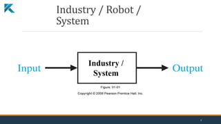
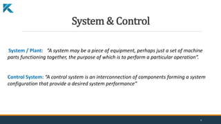
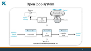
Download to read offline
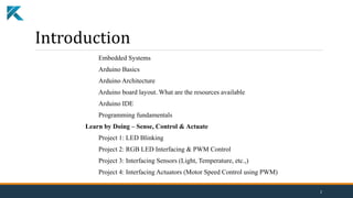
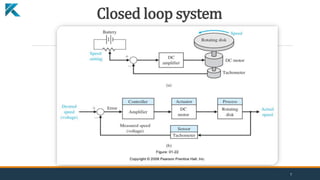
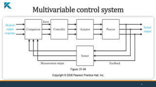
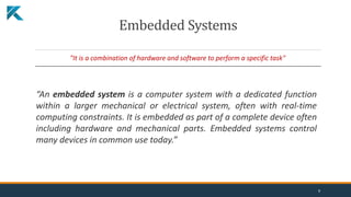
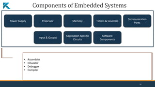
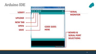
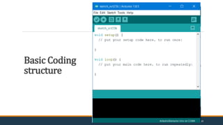
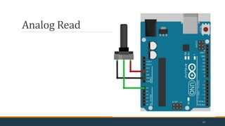
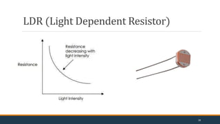
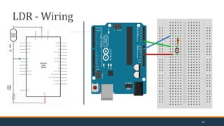
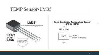
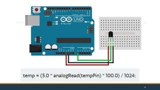
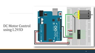
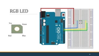


The document provides an overview of an Arduino workshop that covers embedded systems and the Arduino development board. It includes sections on Arduino basics, architecture, components, programming fundamentals, and example projects interfacing LEDs, sensors and actuators. The workshop introduces concepts like open and closed loop control systems. It also explains the Arduino IDE, basic coding structures like setup and loop functions, and how to interface common electronic components like sensors, displays and motors to an Arduino board. Project examples include blinking an LED, controlling an RGB LED using PWM, reading from light and temperature sensors, and controlling motor speed.