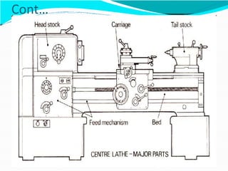
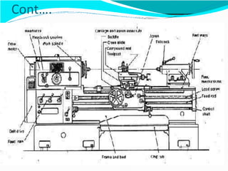
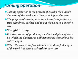
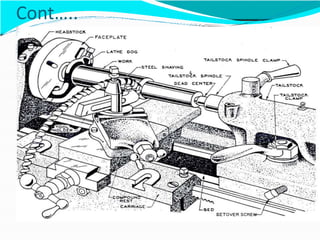
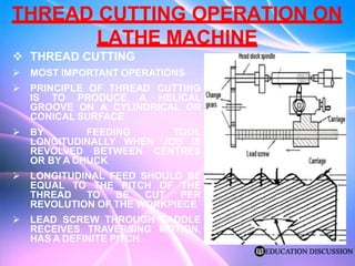
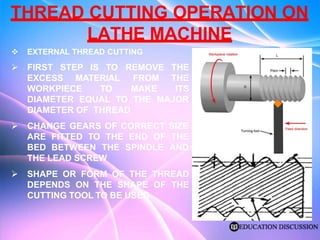
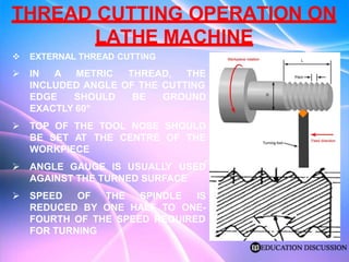
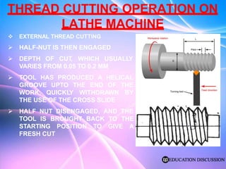
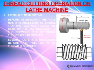
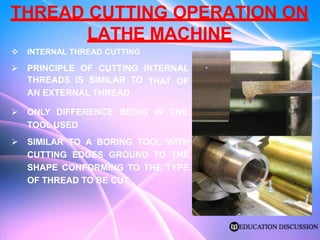
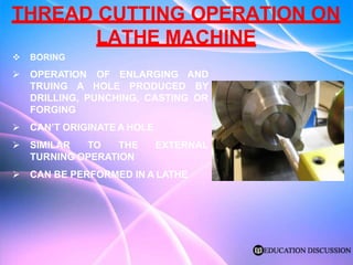
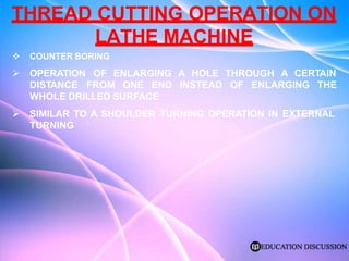
2. WHAT IS A LATHE?
⚫The lathe is a versatile machine tool in which the work
is held and rotated.
⚫A cutting tool is moved along the work to produce
cylindrical shapes (turning), or across the work to
form flat surfaces (facing).
⚫The speed of thework can bevaried tosuitdifferent
diameters, operations or materials.
⚫ The movements of the tool can be combined to
produce a variety of cylindrical and f lat surfaces.
⚫ The general purposeof a lathe is usuallyreferred toa
center lathe. It Is the type most commonly found in
anyworkshop
3. Observe the following important points when
using lathes:
⚫Be tidy
⚫Wear suitable clothes
⚫Use correct tools and equipment
⚫Becareful
⚫Behave safely
⚫Wear adequate eye protection
⚫Use correct lifting methods
⚫Useserviceable tools
4. Cont…..
⚫The primary function of a lathe is to provide a means of
removing metal by rotating thework and feeding acutting
tool against thework.
⚫Thereare three featuresof a lathe:
⚫A support forthe lathecomponents
⚫A meansof holding and rotating thework
⚫A method of holding and removing thecutting tool
⚫5 MAJOR PARTS OF A LATHE
⚫The Bed
⚫The Headstock
⚫TheTailstock
⚫The Carriage
⚫The Feed Mechanism
7. Parts of the lathe machine and
their functions
BED
⚫The bed is the partof the lathe that providessupport
for the other components. It is the foundation on
which all theotherpartsare fitted.
HEADSTOCK
⚫The headstock is the lathe feature that provides the
meansof holding and rotating thework accurately.
TAILSTOCK
⚫The tailstock is used mainly tosupport the right hand
end of the work. It may be moved and clamped in
positionalong the bed.
8. Cont….
The tailstock spindle is located at the same heightand
parallel to the headstock spindle.
⚫The spindle may be moved in and outof the body by
meansof a hand wheel and threaded spindle.
CARRIAGE
⚫The carriage is the lathe that provides the method of
holding and moving thecutting tool accurately.
⚫It consists of two major parts:
⚫Apron
⚫Saddle
9. Cont…
⚫a . APRON
⚫Theapron is bolted to the frontof the saddle.
⚫ It contains the mechanism for moving and controlling
thecarriage.
⚫b . SADDLE
⚫The saddle is the partof thecarriage that fits across
and moves along the bed, between the head and
tailstock.
⚫The cross slide is mounted on topof the saddleand
providesa cross movement for thecutting tool.
⚫The slide is at right angles to the bed and is moved by
meansof a screwed spindle fitted with a handle.
10. Cont…..
⚫Thecompound rest is fitted on topand to the frontof
thecross slide.
⚫The compound rest may be swiveled horizontally
through 360.
⚫The topslide is fitted on topof thecompound rest.
⚫ It providesa meansof supporting the tool post, which
holds thecutting tool.
⚫The topslide provides a limited horizontal movement
for thecutting tool.
⚫Byswiveling thecompound rest, the topslide may be
setan angle to thecross slide.
⚫Normally thecompound rest is setso that the topslide
is at the right angles to thecross slide.
11. Cont….
FEED MECHANISM
⚫Most center lathes have some form of power feed
mechanism to provide automatic movement to the cutting
tool.
⚫Power feed can beapplied to both thesaddle and cross
slide.
a. QUICK CHANGE BOX
⚫This box provides a means of changing the speed of the
feed shaft.
⚫The rate of feed can be varied in relation to the revolutions
of thework to suitdifferent materialsand operations.
b. FEED SHAFT
⚫Power is transmitted from the rear end of the headstock
spindle through thequick change gear box to the feed shaft
located at the front of the lathe bed.
12. Cont….
⚫ c. LEAD SCREW
⚫ Center lathesequipped with power feed also have provision forscrewcutting. A
special threaded spindle is mounted on the front of the lathe bed adjacent to
the feed shaft. It is driven through thequick changegear box.
⚫ Both the lead screw and the feed shaft pass through the apron of the carriage.
Controls on the apron enable the feed shaft or the lead screw to be connected
to thecarriage.
d . FEED LEVER
When the feed lever is engaged power is connected from the feed shaft to the
saddleand crossslide. This provides automatic feeding for facing and turning.
e. LEAD SCREW ENGAGEMENT LEVER
⚫ The lead screw is connected and released from thecarriage by meansof half
nuts. The lead screw engagement lever on the apron operates the half nuts.
These nuts are halved toenable the lead screwto beengaged ordisengaged
easily.
⚫ An interlocking mechanism between the levers prevents the lead screwand the
feed shaft from being engaged at thesame time.
⚫ The arrangement of gears in the feed drive mechanism provides a means of
reversing thedirection of rotation of the feed shaftand the lead screw. Moving
the feed directional lever to reversedoes this.
⚫
13. Cont….
6.TOOL POST
⚫The tool post is fixed on the top of the top slide.
⚫Several typesare used. Theyall have the featuresof
firmly supporting and holding thecutting tool.
⚫The mostwidelyused types are:
1. Square tool post
2. Rigid tool post
3. Standard tool post
⚫The square tool post is a common type.
⚫Itprovides positions for holding fourdifferent cutting
tools. The post can be indexed to position a selected
tool against thework.
14. Cont…
7.HEADSTOCK ACCESSORIES
Types of spindle noses
⚫There are fourtypesof headstock spindle noses to
whichaccessories are fitted. Theyare:
⚫Threaded spindle
⚫Taper and locking ring
⚫Cam lock
⚫Bolted
7.aThreaded spindle
⚫Accessoriesare screwed directlyon to the spindle.
⚫The fit of the threaded holds theaccessory true to the
axis of the spindle. A shoulder bears against the
necessary to hold it square to the spindle.
16. Cont….
7.b Taper and locking ring
⚫When a threaded locking ring is tightened the
accessory is firmly held on the taper.
7.c Cam lock
⚫When the cam locks are tightened, the accessory is
drawn firmlyon toa short taperand againsta flange.
7.d Bolted
⚫The accessory is bolted to a flange on the spindle by a
number of studs that protrude from the rear face of the
accessory.
⚫ A short taper locates theaccessorycentrally. Drive is
provided bya locating key.
17. Cont…
7.1 TYPES OF ACCESSORIES
⚫Theaccessories fitted to the headstock spindleare used for
holding ordriving thework.
⚫Theaccessories are:
Drive plate
Face plate
Chucks
Headstock center
7.1a The drive plate
⚫The plate is used todrivework that has been set up
between centers.
7.1bThe faceplate
⚫The face plate is used to hold and drive work thatcannot be
held between centers or in achuck.
18. Cont….
7.1c Chucks
⚫Chucksarework holding devices, which grip work of
varioussize and shape by meansof adjustable jaws.
⚫The mostcommonlyused chucksare:
Three jawself - centering chuck
Four jaw independent chuck
The Three jawself - centering chuck is used to hold
round and hexagonal work.
• A chuck key is used torotatea scroll that moves the
three jawssimultaneously.
The Four jaw independentchuck is used to hold
regular and irregular or odd shaped work.
19. Cont….
Advantages:
⚫Each jaw can be moved independently
⚫Work can be held very firmly becauseeach jaw
opposes theothers
⚫Work can be set up torunvery true byadjusting the
jawsand checking thework with a dial indicator
⚫Each jaw can be reserved independently to enable odd
shaped work to be held
⚫Concentriccircles marked on the faceassist in locating
work centrally
20. LATHE CARRIERS
⚫ Work to be turned between centers is driven bya
clamp attached to the end of the work.
⚫Theclampcalled acarrier has a leg or tail that locates
against the pin of the driving plate fitted to the lathe
spindle.
⚫Bent tail carriers engage intoa slot in thedrive plate.
22. TAILSTOCK CENTERS
⚫ The tailstock center is held in the tapered boreof the tailstock spindle. It
supports the right hand end of work to be turned between centers.
⚫ Plaincenters
⚫ Plain centersare hardened. Thework rotateson the tailstockcenter, therefore,
the mating surfaces between thecenterand thework must be lubricated.
⚫ Live center
⚫ Live center are tailstock center that run on roller or ball bearings. This enables
the point of the center to rotate with the work.
⚫ Excessive pressureon thecenterwould cause the bearings tooverheatand
become damaged.
⚫ Live center have the following advantages:
⚫ Lubrication is not needed between the center and the work
⚫ The work can be rotated at a higher speeds
⚫ Heavy cutting loads can becarried by thecenter
⚫ Pipecenters
⚫ Pipe centersaresimilarto live centers. Cones can beattached toenable the
centertosupport work that hasa large bore.
⚫ Pipe centerswould not normally be run atas high a speed as a live center.
24. STEADY RESTS
⚫Steady restsare latheattachmentused tosupport long
or slender work.
⚫They prevent thework from being bentordeflected by
thecutting tool during machining.
Twotypesof steadiesare used. Theyare:
⚫Travelling steady
⚫Fixed steady
25. Cont….
Travelling steady
⚫The travelling steady is bolted to the saddleof the
lathe and moves along with the cutting tool.
⚫The steady is used to prevent long slender work from
springing away from thecutting tool while thework is
being turned.
⚫The steadyconsistsof a frame holding twoadjustable
bearing pads. The padsare positioned 90 apart.
⚫One pad is situated behind thework, directlyopposite
thecutting tool.
⚫Theotherpad is situated on topof thework.
⚫Each pad is adjusted by meansof a screw thread and
can be locked in the required position.
27. Cont…..
Fixed steady
⚫The fixed steady is bolted directlyon the topof the
lathe bed.
⚫Itcan be positioned anywherealong the bed.
⚫The steady is used tosupport long slenderwork that is
held between centers, or to support one end of long
work that has itsotherend held in a chuck.
⚫The steadyconsistsof a frame that has threeadjustable
bearing pads.
⚫Each pad is operated bya screw thread and can be
locked in the required position.
29. TOOL HOLDERS
Straight tool holder: is used forgeneral purpose
machining and for thread cutting.
⚫Some makesof holders have the letter S stamped on
their bodies to make them easily identifiable.
Right hand tool holder: is used for facing operation
and for machining work close to the tailstock. Some
makes of holders have the letter R stamped on their
bodies to make them easily identifiable.
Left hand tool holder: is used for facing operations
and for machining work close to the headstock.
• Some makesof holders have the letter L stamped on
their bodies to make them easily identifiable.
31. LATHE MACHINE OPERATIONS AND
Functions of a lathe machine
A. Facing operation
⚫Facing operation is the process of removing stock at the
end of the work piece thus reducing its length and
making the end square with both the work and the lathe
axis.
Methods of Facing
⚫ From center to out
⚫From out to center
33. Procedure for facing
⚫Measure the length todetermine how much stock is to
be removed.
⚫Machineoff justenough stock from the firstend to
clean up thatend.
⚫Feed the facing tool from centerout, rather than from
theoutside toward thecenter.
⚫Machine the remaining stock from theoppositeend to
face it to the length required.
⚫Step facing:
⚫ is the removal of large amount of material by making
series of deep cuts longitudinally rather from the center
going outward.
35. Turning operation
⚫Turning operation is the process of cutting the outside
diameter of the work piece thus reducing its diameter.
⚫The purpose of turning work on a lathe is to produce a
true cylindrical surface and to cut the work to a specific
size.
⚫Straight turning
⚫It is the process of producing a cylindrical piece of work
on which the diameter is uniform in size throughout its
entire length.
⚫When the turned surfaces do not extend the full length
of the work it is term as shoulder turning.
38. Taper turning
⚫A taper can be defined as a uniform change of
diameteralong the length of a cylinder. The surfaceso
produced is a conical surface.
⚫Tapers provide rapid and accurate means of aligning
and holding machine parts. The taperensuresa tight
fit, and partsare readily assembled and separated.
⚫Tapers permit the interchangeabilityof certain cutting
tools or attachments with extreme accuracy. Some
milling cutters, twist drills, reamers, and lathe centers
have tapered shanks which fit into the tapered spindle
of a machine tool
40. Methods of taper turning
a. Compound rest method
⚫ By swiveling thecompound rest to the desired angleand feeding
the tool by hand using the topslide hand wheel.
⚫ Short lengthorstep taperscan becut.
b .Taper attachment method
⚫ The taperattachment is a fixed casting attached to the back of
thecarriage. It is used forturning and boring tapers.
⚫ Into thecasting is filled a sliding part, on the topof which is a
guide bar.
⚫ Eithertheguide baror the sliding part is graduated in degreesat
oneend, and in taperperfooton theotherend.
⚫ A clamp holds the sliding part to the lathe ways in a fixed
position. When theguide bar is set toacertain taper, thecross –
feed follows the set angle or taper and in turn produces thin
taper on the work piece.
42. Tailstock off – set method
⚫When the lathe is notequipped with a taperattachment
and the part to be turned is held between centers, the
tailstock center may be offset from the centerline to
producea taper.
⚫Theamount that the tailstock centercan beoffset is
limited.
⚫This method is particularlysuited to the turning of slow
tapers.
⚫Standard taperscannot be turned on a long work piece.
⚫Holding work between chuck and center is not
advisable.
⚫
45. Chamfering operation
⚫Chamfering :is theoperationof producing a beveled edge
ata specified angleon theend of a turned diameter.
⚫This isdone to break off or remove thesharpedgeand
finish thework piece.
⚫Chamfering is also done to aid in starting a round piece,
such as adowel pin, straight in a hole.
⚫Procedures for chamfering
⚫Set thecompound slideat the required angleand feeding
the tool bit by hand to producea specified chamfer
⚫When the chamfer angle and the length are not specified,
the tool bit may be set at an angle
⚫Then feed against the revolving work piece, ora file may be
used
47. KNURLING, GROOVING, AND
FORM TURNING
⚫Operations such as knurling, grooving, and form turning
are used to alter either the shape or the finish of a round
work-piece.
⚫These operations are normally performed on work
mounted in achuck; however, theycan also be performed
on work mounted between lathe centers if certain
precautionsareobserved.
⚫Knurling is used to improve the surface finish on thework
and providea handgripon thediameter.
⚫Grooving is used to providea relief at theend of a thread or
a seat forsnapor O-rings.
⚫Form turning produces aconcave orconvex form on
internal orexternal surfaces of awork piece.
48. Knurling
⚫ Knurling is a process of impressing a diamond-shaped or straight-line
pattern into thesurfaceof thework piece to improve itsappearance orto
provide a better gripping surface.
⚫ Straight knurling is often used to increase thework piece diameterwhen a
press fit is required.
⚫ Diamond- and straight- pattern rollsareavailable in threestyles: fine,
medium, and coarse (Figure 1).
⚫ The knurling tool (Figure 2) is a tool post-type tool-holderon which pairof
hardened-steel rolls is mounted.
⚫ These rolls may beobtained in diamond and straight-linepatterns, and in
coarse, medium, and fine pitches.
⚫ Some knurling toolsare madewith the threevarious pitched rollerson one
holder (Figure 3).
⚫ Fine, medium, and Coarse Diamond Patterns
⚫ Fine, medium, and Coarse Straight Patterns
⚫ Figure 2. A Knurling tool with oneset of rolls in a self-centering head
⚫ Figure 3. A Knurling tool with threesets of rolls in a revolving head
50. GROOVING
⚫Grooving is commonlycalled recessing, undercutting,
or necking.
⚫It is often doneat theend of a thread to permit full
travel of the nut up toa shoulder, orat theedgeof a
shoulder to ensure a proper fit of mating parts.
Grooves are generally square, round or V-shaped
⚫Rounded grooves are usually used where there is a
strain on the part and where a square corner would
lead to a fracturing of the metal at this point.
52. FORM TURNING ON A LATHE
⚫It is often necessary to form irregular shapes or
contourson a work-piece. Form turning may be done
on a lathe by three methods:
⚫Freehand
⚫Form-turning tool
⚫Hydraulic tracer attachment
⚫TURNING A FREEHAND FORM OR RADIUS
⚫Freehand form turning probably presents the greatest
problem to the beginning latheoperator. Coordination
of both hands is required and practice is important in
mastering this skill.
53. FORM TURNING TOOLS
⚫ A form turning tool conveniently formssmallerradii and
contourson awork piece.
⚫ The lathe tool bit is ground to thedesired radius and used to
form the contour on the work piece.
⚫ Tool bits mayalso beground to produce aconcave radius
⚫ This method of forming radii and contours eliminates the need
for checking with a gage or template once the tool bit is ground
to thedesired shape.
⚫ Duplicate contours mayalso be formed on several work pieces
when thesame tool bit is used.
⚫ When producing aconvex radius, it is necessary to leaveacollar
of thedesired sizeon thework piece
⚫ Toproduce agood finish by this method, thework should be
revolved slowly.
⚫ The tool should be fed into thework slowly while cutting oil is
applied.
⚫ Toeliminate chatter during the cutting operation, the cutting
tool should be moved slightly back and forth (longitudinally).
55. DRILLING, BORING, AND TAPPING
⚫Internal operations such as boring, reaming, and
tapping can be performed on work being held in a
chuck.
⚫Boring toolsare mounted in the tool post, whiledrills,
reamers, and taps may be held either in a drill chuck
mounted in the tailstock spindle or directly in the
tailstock spindle.
⚫Since the work held in the chuck is generally
machined true, theseoperations are usually machined
concentric totheoutsidediameterof theworkpiece.
56. BORING
⚫Boring is theoperationof enlarging and truing adrilled or
cored holewith a single-pointcutting tool.
⚫Boring can produce special diameter holes, forwhich no
drills are available.
⚫Holes may be drilled in a lathe; however, such holes are
generally not considered accurate although thedrill may
have started straight.
⚫During the drilling process, the drill may become dull or
hita hard spot or blowhole in the metal, which will cause
thedrill towander or run off center.
⚫If such a hole is reamed, the reamer will follow the drilled
holeand as a result, the holewill not be straight.
⚫Therefore, if it is important thata reamed hole is straight,
and true, the holeshould first be bored and reamed.
57. Cont….
⚫REAMING
⚫Reaming may be performed in a lathe toquicklyobtain
an accurately sized hole and to produce a good surface
finish.
⚫Reaming may be performed after a hole has been
drilled or bored. If a true, accurate hole is required; it
should be bored before the reaming operation.
58. TAPPING
⚫Tapping is one method of producing internal threads on a
lathe.
⚫The tap is aligned by placing the point of the lathe dead
center in the shank end of the tap toguide itwhile the tap
is turned bya tapwrench.
⚫A standard tap may be used for this operation; however, a
gun tap is preferred because thechipsarecleared ahead of
the tap.
⚫When tapping a hole in a lathe, lock the spindleand turn
the tap by hand.
61. THREAD CUTTING OPERATION ON
LATHE MACHINE
INTRODUCTION
A MACHINE TOOL IS A POWER DRIVEN APPARATUS
DESIGNED TO PERFORM METAL CUTTING BY VARIOUS TYPES
OF CUTTING TOOLS
MOSTLY THE MACHINED SURFACES ARE REQUIRED TO BE
CYLINDRICAL OR FLAT
THE WORK OF MACHINE TOOLS IN GENERAL IS CONCERNED
WITH PRODUCING ONE OR BOTH
62. THREAD CUTTING OPERATION ON
LATHE MACHINE
INTRODUCTION
THE LATHE IS A MACHINE TOOL
REMOVES THE METAL FROM A PIECE OF WORK TO GIVE THE
REQUIRED SHAPE AND SIZE.
BY HOLDING THE WORK SECURELY AND RIGIDLY ON THE
MACHINE AND THEN TURNING IT AGAINST CUTTING TOOL
REMOVE METAL FROM THE WORK IN THE FORM OF CHIPS
63. THREAD CUTTING OPERATION ON
LATHE MACHINE
COMMON OPERATIONS
THREAD CUTTING - A THREAD IS A UNIFORM HELICAL
GROOVE CUT INSIDE OF A CYLINDRICAL WORKPIECE, OR ON
THE OUTSIDE OF A TUBE OR SHAFT
BORING - ALSO CALLED INTERNAL TURNING, IS USED TO
INCREASE THE INSIDE DIAMETER OF A HOLE. THE ORIGINAL
HOLE IS MADE WITH A DRILL, OR IT MAY BE A CORED HOLE IN
A CASTING
64. THREAD CUTTING OPERATION ON
LATHE MACHINE
THREAD CUTTING
MOST IMPORTANT OPERATIONS
PRINCIPLE OF THREAD CUTTING
IS TO PRODUCE A HELICAL
GROOVE ON A CYLINDRICAL OR
CONICAL SURFACE
BY FEEDING TOOL
LONGITUDINALLY WHEN JOB IS
REVOLVED BETWEEN CENTRES
OR BY A CHUCK
LONGITUDINAL FEED SHOULD BE
EQUAL TO THE PITCH OF THE
THREAD TO BE CUT PER
REVOLUTION OF THE WORKPIECE
LEAD SCREW THROUGH SADDLE
RECEIVES TRAVERSING MOTION,
HAS A DEFINITE PITCH
65. THREAD CUTTING OPERATION ON
LATHE MACHINE
EXTERNAL THREAD CUTTING
FIRST STEP IS TO
EXCESS MATERIAL
WORKPIECE TO
REMOVE THE
FROM THE
MAKE ITS
DIAMETER EQUAL TO THE MAJOR
DIAMETER OF THREAD
CHANGE GEARS OF CORRECT SIZE
ARE FITTED TO
BED BETWEEN
THE END OF THE
THE SPINDLE AND
THE LEAD SCREW
SHAPE OR FORM OF THE THREAD
DEPENDS ON THE SHAPE OF THE
CUTTING TOOL TO BE USED
66. THREAD CUTTING OPERATION ON
LATHE MACHINE
EXTERNAL THREAD CUTTING
IN A METRIC THREAD, THE
INCLUDED ANGLE OF THE CUTTING
EDGE SHOULD BE GROUND
EXACTLY 60°
TOP OF THE TOOL NOSE SHOULD
BE SET AT THE CENTRE OF THE
WORKPIECE
ANGLE GAUGE IS USUALLY USED
AGAINST THE TURNED SURFACE
SPEED OF
REDUCED BY
THE SPINDLE IS
ONE HALF TO ONE-
FOURTH OF THE SPEED REQUIRED
FOR TURNING
67. THREAD CUTTING OPERATION ON
LATHE MACHINE
EXTERNAL THREAD CUTTING
HALF-NUT IS THEN ENGAGED
DEPTH OF CUT
, WHICH USUALLY
VARIES FROM 0.05 TO 0.2 MM
TOOL HAS PRODUCED A HELICAL
GROOVE UPTO THE END OF THE
WORK, QUICKLY WITHDRAWN BY
THE USE OF THE CROSS SLIDE
HALF NUT DISENGAGED, AND THE
TOOL IS BROUGHT BACK TO THE
STARTING POSITION TO GIVE A
FRESH CUT
68. THREAD CUTTING OPERATION ON
LATHE MACHINE
EXTERNAL THREAD CUTTING
BEFORE RE-ENGAGING THE HALF
NUT, IT IS NECESSARY TO ENSURE
THAT THE TOOL WILL FOLLOW THE
SAME PATH IT HAS TRAVERSED IN
THE PREVIOUS CUT, OTHERWISE
THE JOB WILL BE SPOILED
NECESSARY
DEPTH OF
SEVERAL CUTS ARE
BEFORE THE FULL
THREAD IS REACHED.
69. THREAD CUTTING OPERATION ON
LATHE MACHINE
INTERNAL THREAD CUTTING
PRINCIPLE OF CUTTING INTERNAL
THAT OF
THREADS IS SIMILAR TO
AN EXTERNAL THREAD
ONLY DIFFERENCE BEING IN THE
TOOL USED
SIMILAR TO A BORING TOOL WITH
CUTTING EDGES GROUND TO THE
SHAPE CONFORMING TO THE TYPE
OF THREAD TO BE CUT
70. THREAD CUTTING OPERATION ON
LATHE MACHINE
INTERNAL THREAD CUTTING
HOLE IS FIRST BORED TO THE ROOT
DIAMETER OF THE THREAD.
TOOL IS FIXED ON THE TOOL POST
OR ON THE BORING BAR AFTER
SETTING IT AT RIGHT ANGLES TO
THE LATHE AXIS, USING A THREAD
GAUGE/ANGLE GAUGE.
DEPTH OF CUT IS GIVEN BY THE
COMPOUND SLIDE AND THE
THREAD IS FINISHED IN THE USUAL
71. THREAD CUTTING OPERATION ON
LATHE MACHINE
BORING
OPERATION OF
TRUING A HOLE PRODUCED
ENLARGING AND
BY
DRILLING, PUNCHING, CASTING OR
FORGING
CAN’T ORIGINATE A HOLE
SIMILAR TO THE EXTERNAL
TURNING OPERATION
CAN BE PERFORMED IN A LATHE
72. THREAD CUTTING OPERATION ON
LATHE MACHINE
COUNTER BORING
OPERATION OF ENLARGING A HOLE THROUGH A CERTAIN
DISTANCE FROM ONE END INSTEAD OF ENLARGING THE
WHOLE DRILLED SURFACE
SIMILAR TO A SHOULDER TURNING OPERATION IN EXTERNAL
TURNING
73. THREAD CUTTING OPERATION ON
LATHE MACHINE
TAPER BORING
THE PRINCIPLE OF TURNING A TAPER HOLE IS SIMILAR TO THE
EXTERNAL TAPER TURNING OPERATION
ACCOMPLISHED BY ROTATING THE WORK ON A CHUCK AND
FEEDING THE TOOL AT AN ANGLE TO THE AXIS OF ROTATION
OF THE WORK PIECE
74. Machining Parameters
⚫Primary Machining Parameters
⚫Cutting Speed – (v)
⚫ Primary motion
⚫ Peripheral speed
⚫Feed – (f)
m/min ft/min
⚫ Secondary motion
⚫ Turning: mm/rev in/rev
⚫ Milling: mm/tooth in/tooth
⚫Depth of Cut – (d)
in
⚫ Penetration of tool below original work surface
⚫ Single parameter mm
⚫ Resulting in Material Removal Rate – (MRR)
MRR = v f d mm3/s in3/min
⚫where v = cutting speed; f = feed; d = depth of cut
76. Lathe Speeds and Feeds
Determining the most advantageous feeds and speeds
for a particular lathe operation depends on numerous
factors :such as :
the kind of material being worked on,
the typeof tool,
thediameterand length of thework piece,
the typeof cutdesired (rough or finished),
thecutting oil used, and
thecondition of the lathe being used.
77. Cutting Speed
(a) The cutting speed of a cutter bit is defined as :
⚫the number of feet of work-piece surface, measured at
the circumference, that pass the cutter bit in 1
minute.
⚫The cutting speed, expressed in feet per minute
(fpm), must not be confused with the spindle speed
of the lathe which is expressed in revolutions per
minute (rpm).
⚫ To obtain uniform cutting speed, the lathe spindle
must be revolved faster for work-pieces of small
diameter and slower for work-pieces of large
diameters.
78. Cont……
(b) The proper cutting speed for a given job depends upon:
the hardness of the material being worked on,
the material of thecutter bit, and
the feed and depthof cut to be used.
Table 2 lists specific ranges of cutting speeds for straight
turning and for threading under normal conditions. It is
proper to start machining operations at these speeds and
observe theeffecton thecutter bitand work-piece.
If thecutter bitdoes not cut satisfactorily, thespeed
should be reduced.
If itdesired to increase eitherthe feed or thedepth of cut,
the cutting speed should be proportionally reduced to
preventoverheating and excessivecutter bitwear
80. Cont…
⚫(c) To determine the rotational speed necessary to
produceagiven cutting speed:
⚫ it is necessary to know the diameter of the work-
piece to be cut.
⚫Tocalculate the spindlespeed, knowing thediameter
of theworkpiece,
⚫use the following formula:
83. Cont….
⚫(d) Another factor toconsider when selecting cutting
speed includes
the useof cutting oils,
the length and diameterof thework-piece, and
thecondition of the lathe.
⚫If a large stream of proper cutting oil is applied to the
work-piece at the cutter bit, the cutting speed can be
increased as much as 40 percent.
⚫If the diameter of the work-piece is small and its length is
great enough to set up vibrations due to the speed, a poor
finish will result; to correct this condition, the speed must
necessarily be reduced.
⚫The lathe may also be in poor condition so that high speeds
will cause harmful vibrations.
84. Feed.
⚫(a) Feed is the term applied to thedistance thecutter
bitadvances foreach revolutionof thework-piece.
⚫ Feed is specified in inches perrevolution.
⚫ Since the best feed depends upon a number of factors
such as :
depthof cut,
type of material,
sizeof work-piece, and
condition of the lathe,
⚫ it is difficult to list the best feed for thedifferent
materials.
85. Cont…
⚫(b) Rough Cuts. For rough cuts, the feed may be
relatively heavy since the surface need not be
exceptionallysmooth. For most materials, the feed for
rough cuts should be 0.010 to 0.020 inch per
revolution.
⚫The feed may be 0.040 inch on large latheswith larger
diameter work-pieces.
⚫Care must be taken when turning slenderwork-pieces
as a heavy cut may bend the piece, ruining it.
⚫In thiscase, it is best to reduce the feed to 0.008 - 0.015
inch perrevolution.
86. Cont…..
(c) Finish Cuts. For finish cuts,
⚫a light feed is necessary since a heavy feed causes a
built-upedge to form on thesurface, which producesa
poor finish.
⚫If a large amount of stock is to be removed, it is
advisable to takeoneor more roughing cutsand then
take light finishing cutsat relatively high speeds.
⚫ For most materials, the feed for finishing cuts should
be 0.003 to 0.010 inch per revolution. An exception is
finishing soft metal likealuminumwherea broad nose
cutter bit is used at feeds as great as 1/8 to 1/2 inch per
revolution.
88. (4) Depth of Cut.
(a) Thedepth of cut regulates the reduction in thediameterof the
work-piece foreach longitudinal traverseof thecutterbit.
⚫ Thework-piecediameteris reduced by twice thedepthof thecut in
each complete traverseof thecutter bit.
⚫ Generally, thedeeper thecut, the slowerthe speed, sincea deepcut
requires more power.
(b) Rough Cuts. Thedepth of thecut forroughing is generally five to
ten timesdeeper than the feed.
o The reason forthis is that moreof thecutting edgeof thecutterbit is in
contact with the work-piece for the amount of metal being removed
permitting a greaterspeed to be used. Forroughing with feeds of from
0.010 to 0.020 inch perrevolution, thedepth of cutshould be between
3/16 and 1/4 inch.
o Deeper cuts up to 1/2 inch can be taken but the feed should be
proportionately reduced. A heavy cut maycause thework-pieceand
the cutter bit to chatter; in this case the depth of cut should be
reduced.
(c) Finish Cuts. Finish cutsaregenerallyvery light; therefore, the
cutting speed can be increased since thechip is thin.
89. Cont…
⚫d. Cutting Oils.
⚫(1) General. The chief purpose of cutting oil is to cool the
cutter bitand thework-piece. The name "coolant" isoften
given to theoil. A cutter bit will last longer and will be
capable of withstanding greater speeds without
overheating when acutting oil is used. A cutting oil also
helps lubricate the cutter bits, improves the finish of the
work-piece, guards against rusting, and washes awaychips
from thecutting area.
⚫(2) Use. In production operations, the practice is to flood
the work-piece and the cutter bit with cutting oil in order
to obtain the full benefit of its use. For effective cooling, it
is important that the oil be directed at the exact point of
thecutter bitcontact. A large stream at low velocity is
preferred toa small stream at highvelocity. In small shops
where pump equipment is not available, cutting oils are
used only for finishing and delicate operations. It is
general practice in this case to apply the cutting oil only
when actually required.