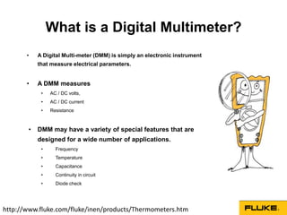
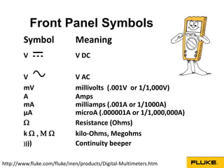
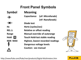
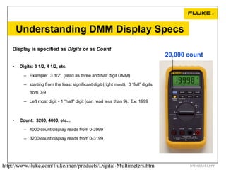
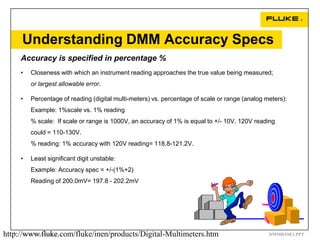
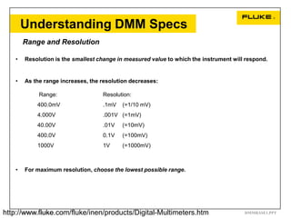
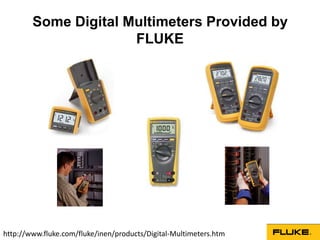
A digital multimeter (DMM) is an electronic instrument that measures voltage, current, and resistance. A DMM displays measurements digitally and can measure AC and DC voltage, AC and DC current, and resistance. It may also have features to measure frequency, temperature, capacitance, continuity, and diode performance. A DMM uses symbols on its front panel to indicate the measurement units. DMM specifications include the number of display digits, measurement accuracy, and voltage/current ranges and resolutions. DMMs are used to troubleshoot circuits by measuring voltage, current, and resistance. True RMS DMMs provide accurate measurements of non-sinusoidal waveforms.


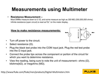


![Electrical measurement & measuring instruments [emmi (nee-302) -unit-2]](https://cdn.slidesharecdn.com/ss_thumbnails/electricalmeasurementmeasuringinstrumentsemmi-nee-302-unit-2-170607090943-thumbnail.jpg?width=640&height=640&fit=bounds)


