Download to read offline

![Enhancement Of Specific Power Output Of A Gas Turbine Using Filtered Chilled Air
www.iosrjournals.org 36 | Page
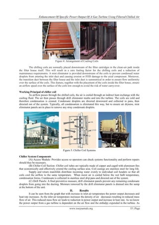
the mass flow of air in the turbine reduces the capacity of the gas turbine to consume fuel also decreases, since
the firing temperature is fixed. The reduction in the fuel also leads to reduced
Figure 6: Effect of Inlet Air Temperature on Gas Turbine Power Output
Table 1: Calculations for Chiller Capacity
Temperature in ˚C Chiller Capacity in TR Gas Turbine Power
Output in MW
Approximate cost @
0.45 lakhs/Ton
33 102.19
25 643.3352 107.9 290
22 1558.041 110.04 701
20 2835.147 111.47 1,276
18 3621.67 112.8 1,630
15 4717.452 114.94 2,123
III. Conclusions
Using air at atmosphere pressure and temperature gas turbine produces power of 102.19MW. But when
cold air at STP is used the turbine output increases to 114.94 MW.
Hence percentage increases in turbine is 12.47%.
Air is cooled from 33˚C to 15˚C using chiller. Under this condition chiller capacity is 4717.45TR.
Bibliography
[1] Farzaneh-Gord, M.; Deymi-Dashtebayaz, M. Effect of various inlet air cooling methods on gas turbine performance. Energy, 36,
1196–1205, 2011.
[2] ASHRAE. ASHRAE Handbook – HVAC Systems and equipment (SI). Atlanta, 2008.
[3] Al-Ibrahim A. M.; Varnham, A. A review of inlet air-cooling technologies for enhancing the performance of combustion turbines in
Saudi Arabia. Applied Thermal Engineering, 30, 1879–1888, 2010.
[4] Amell, A. A.; Cadavid, F. J. Influence of the Relative Humidity on the Air Cooling Thermal Load in Gas Turbine Power Plant.
Applied Thermal Engineering, 22, 1529–1533, 2002.
[5] Ibrahim, T. K.; Rahman M. M.; Abdalla A. N. Improvement of gas turbine performance based on inlet air cooling systems: A
technical review. International Journal of Physical Sciences, 6 (4), 620-627, 2011.
[6] Jaber, Q. M. Jaber, J. O.; Khawaldah, M. A. Assessment of power augmentation from gas turbine power plants using different inlet
air cooling systems. Jordan Journal of Mechanical and industrial Engineering, 1(1), 7–15, 2007.
[7] Alhazmy, M. M.; Najjar, Y. S. H. Augmentation of gas turbine performance using air coolers. Applied Thermal Engineering,
24,415– 429, 2004.
[8] Nasser, A. E. M.; El-Kalay, M. A. A heat-recovery cooling system to conserve energy in gas-turbine power stations in the Arabian
Gulf. Applied Energy, 38 (2), 133–142, 1991.
[9] Dawoud, B.; Zurigat Y. H.; Bortmany, J. Thermodynamic assessment of power requirements and impact of different gas-turbine
inlet air cooling techniques at two different locations in Oman. Applied Thermal Engineering, 25, 1579–1598, 2005.
[10] Hosseini, R.; Beshkani, A.; Soltani, M. Performance improvement of gas turbines of Fars (Iran) combined cycle power plant by
intake air cooling using a media evaporative cooler. Energy Conversion and Management, 48, 1055-1064, 2007.
[11] Brooks, F. J. GE Gas turbine performance characteristics. GE Power Systems. Schenectady, NY. GER-3567H.
[12] Mahmoudi SM, Zare V, Ranjbar F, Farshi L (2009). Energy and exergy analysis of simple and regenerative gas turbines inlet air
cooling using absorption refrigeration. J. Appl. Sci., 9(13): 2399-2407.
108
110
112
114
116
288 291 293 295 298
GasTurbineOutputin
MW
Temperature in K](https://image.slidesharecdn.com/e0763336-150115232919-conversion-gate02/85/Enhancement-of-Specific-Power-Output-of-a-Gas-Turbine-Using-Filtered-Chilled-Air-4-320.jpg)

The document discusses the enhancement of specific power output in gas turbines through inlet air cooling using chilled air. By cooling the air intake, the study shows an increase in power output by up to 12.47%, demonstrating the effectiveness of this cooling method in improving turbine efficiency. The findings suggest that employing chiller systems can significantly boost turbine performance while maintaining operational integrity.