Downloaded 35 times
![Proceedings of the 2nd International Conference on Current Trends in Engineering and Management ICCTEM -2014
INTERNATIONAL JOURNAL OF MECHANICAL ENGINEERING
17 – 19, July 2014, Mysore, Karnataka, India
AND TECHNOLOGY (IJMET)
ISSN 0976 – 6340 (Print)
ISSN 0976 – 6359 (Online)
Volume 5, Issue 9, September (2014), pp. 22-30
© IAEME: www.iaeme.com/IJMET.asp
Journal Impact Factor (2014): 7.5377 (Calculated by GISI)
www.jifactor.com
22
IJMET
© I A E M E
PERFORMANCE EVALUATION AND OPTIMIZATION OF AIR
PREHEATER IN THERMAL POWER PLANT
G.Shruti1, Ravinarayan Bhat2, Gangadhar Sheri3
1(Department of Mechanical Engineering, Srinivas Institute of Technology, Mangalore, 574143, Karnataka, India)
2 (Associate professor , Department of Mechanical Engineering, Srinivas Institute of Technology, Mangalore, 574143,
Karnataka, India)
3(AGM Performance, LANCO-UPCL Nagarjuna Thermal Power Plant, Padubidri, Udupi, 574113 Karnataka, India)
ABSTRACT
This paper presents a performance evaluation and optimization method of an air preheater based on routine
operation data measured onsite at LANCO-UPCL, Nagarjuna thermal power plant Padubidri, Karnataka, India. The work
focuses on the performance of Regenerative type air pre heater (model LAP 13494/2200). The performances were
evaluated before and after radial sector plate clearance adjustments with air preheater tests, and improvement is seen
along with air preheater optimization.
Keywords: Air pre heater, Air leakage, Gas side efficiency, Seals, X-ratio.
1. INTRODUCTION
Modern high capacity boilers are always provided with an air preheater. Air pre-heater is an important boiler
auxiliary which primarily preheats the combustion air for rapid and efficient combustion in the furnace Serving as the last
heat trap for the boiler system, a regenerative air preheater typically accounts for over 10% of a plants thermal efficiency
on a typical steam generator. Considering this, when evaluating the performance of an air preheater one should take into
account all of the process variables [10].
A very good method to improve the overall efficiency of a thermal power plant is to preheat the air. If the
incoming air for combustion is not preheated, then some energy must be supplied to heat the air to a temperature required
to facilitate combustion. As a result, more fuel will be consumed which increases the overall cost and decreases the
efficiency. There are many factors, which contribute to the deterioration of air preheater performance like high seal
leakage, deterioration of heat absorption characteristics of basket elements due to fouling or plugging. Close monitoring
of air pre heater performance and proper instrumentation would enable timely detection of performance degradation. The
combustion air preheater for the large fuel-burning furnaces used to generate steam in thermal power plants [5].
2. LJUNGSTROM AIR PREHEATER (LAP 13494/2200)
The Ljungstrom air preheater is more widely used than any other type of combustion air preheater in the power
industry, because of its compact design proven performance and reliability, and its fuel flexibility. The model LAP
13494/2200 means a Ljungstrom air preheater with rotor diameter of 13494mm is used in UPCL power plant. The
heights of heating elements of 4 sections are respectively 300mm, 800mm, 800mm and 300mm from top to bottom of the
rotor. The cold end heating elements of 300mm height are made of carbon plate while the hot end heating elements are](https://image.slidesharecdn.com/performanceevaluationandoptimizationofairpreheaterinthermalpowerplant-141023093702-conversion-gate02/75/Performance-evaluation-and-optimization-of-air-preheater-in-thermal-power-plant-1-2048.jpg)
![Proceedings of the 2nd International Conference on Current Trends in Engineering and Management ICCTEM
17 – 19, July 2014, Mysore, Karnataka, India
made of common carbon steel. The metal weight of one air preheater is approximately 620 tons, including 465 tons for
the rotor assembly (about 75 percent of the total weight). The air preheater is tri
The model LAP 13494/2200 tri-sector rotary air preheater as shown in Fig
exchanger. Specially corrugated heating elements are tightly placed in the sector compartment of the rotor. The rotor
turns at a speed of 0.99 rpm and is divided into gas channels and air channels. The air side is mad
channels and secondary air channels. When gas flows through the rotor, it releases heat and delivers it to the heating
elements and then the gas temperature drops; when the heated elements turn to the air side, the air passing through them
is heated and its temperature is increased. By continuing maintaining such a circulation, the heat exchange is achieved
between gas and air.
Fig. 1: Trisector rotary air preheater and its important
2.1 Heating Elements
Heating elements are made of carbon steel sheets with special corrugations formed by pressing; the hot end
heating assemblies are profiled in accordance with shapes and sizes of individual sub
by alternately piling up notched undulation sheets with vertical undulations and inclined turbulent corrugations and
sheets only with the same inclined corrugations one by one as shown in Fig 2. All the assemblies of both hot and cold
end heating elements are fastened by welding flat b
23
tri-sector type [10].
Fig. 1 is a counter flow regenerative heat
parts [10]
sub-modules. Each assembly is formed
ed bars and angle steels together [3].
-2014
made of primary air](https://image.slidesharecdn.com/performanceevaluationandoptimizationofairpreheaterinthermalpowerplant-141023093702-conversion-gate02/75/Performance-evaluation-and-optimization-of-air-preheater-in-thermal-power-plant-2-2048.jpg)
![Proceedings of the 2nd International Conference on Current Trends in Engineering and Management ICCTEM
2.2 Sealing System
17 – 19, July 2014, Mysore, Karnataka, India
Fig. 2: Heating Elements
Usually air leaks in to the gas in the air preheater due to pressure differences. This leakage air decreases the
flue gas temperature without extracting the heat.
requirement that the rotating parts should have some working clearance between the static parts to avoid any
interference between them. Here, in air preheaters, rotors are constructed to have high
thermal expansion and these gaps are close with the flexible seal leaves. Major types of seals used in power plant.
• Radial seals
• Axial seals
• Bypass seals
• Circumferential seals
To reduce the air leakage seals are provided. It is an implied
The main purpose of these seals is to reduce the
the Air pre heater.[6]
3. EXPERIMENTAL SET-UP AND PROCEDURE
3.1 Principle of Operation
Air preheater performance test is conducted on rotary regenerative
air preheaters. Various performance indices like air preheater leakage, gas side efficiency, X
this test. A single carbon steel tube with portable gas analyzer and digital thermomete
evaluation.
3.2 Test Procedure
The Instruments used are: Gas analyzer, Digital thermometer, static probe.
3.2.1 Test Set Up – Operating Conditions of Test Runs
Test runs are conducted at an easily repeatable level at
number of mills in service and same total air levels as previous tests. The operating conditions for each test run are as
follows.
a. No furnace or air heater soot blowing is done during the test.
b. Unit operation is kept steady for at least 60 minutes prior to the test.
24
higher clearance to take care of
leakage between the gas and air. Fig 3. Shows sealing system of
Fig. 3: Sealing System
air preheater to improve the efficiency of the
X-ratio are determined using
thermometer is used for performance
defined baseline conditions at full load with same
ion -2014
er r](https://image.slidesharecdn.com/performanceevaluationandoptimizationofairpreheaterinthermalpowerplant-141023093702-conversion-gate02/75/Performance-evaluation-and-optimization-of-air-preheater-in-thermal-power-plant-3-2048.jpg)
![Proceedings of the 2nd International Conference on Current Trends in Engineering and Management ICCTEM -2014
17 – 19, July 2014, Mysore, Karnataka, India
25
c. Steam coil Air heaters (SCAPH) steam supply is kept isolated and gas recirculation dampers if any, are tightly
shut.
d. No mill change over is done during the test.
The test run duration will be the time required to complete two traverses for temperature and gas analysis. Two
separate test crews should sample the gas inlet and outlet ducts simultaneously.
3.2.2 Traverse locations – Gas side
a. The gas inlet traverse plane should be located as close as possible to the air heater inlet. This is done to ensure
that any air ingress from the intervening duct/ expansion joints is not included in air heater performance
assessment.
b. The gas outlet traverse plane should be located at a suitable distance downstream the air heater to allow mixing
of the flow to reduce temperature and o2 stratification. However, it should not be located downstream of other
equipment or access ways that might contribute to air ingress.
3.2.3 Traverse locations – Airside
a. The air inlet traverse plane should be located after any air heating coils and as close as possible to the air heater
inlet. Since the entering air temperature is usually uniform, a single probe with 2 or 3 temperature measurement
points is adequate.
b. The air outlet traverse plane should be located at a suitable distance downstream the air heater to allow mixing
of the flow to reduce the gas stratification as shown in Fig 4.
Fig. 4: Traverse location- airside [10]
3.2.4 Ports and Probes
Typical test port and probe used for the test is shown in Fig 5.
Fig. 5: Ports and Probes [10]](https://image.slidesharecdn.com/performanceevaluationandoptimizationofairpreheaterinthermalpowerplant-141023093702-conversion-gate02/75/Performance-evaluation-and-optimization-of-air-preheater-in-thermal-power-plant-4-2048.jpg)
![Proceedings of the 2nd International Conference on Current Trends in Engineering and Management ICCTEM -2014
17 – 19, July 2014, Mysore, Karnataka, India
( O gl O ge
) * 0.9 * 100
* ( −
)
AL Tgl Tae
( Tge −
Tgnl
)
Tge Tae
= (3)
26
Tubes numbered 1,2, 3 are carbon steel 3/8” OD tubes and tube no. 4 is carbon steel 12-15 mm OD. Tubes
numbered 1, 2 3 are for gas sampling while tube no. 4 is for carrying thermocouple wires for temperature measurement.
d is the flue gas duct width at the test cross-section.
3.2.5 Flue Gas Composition Temperature
A representative value of flue gas composition (O2 / CO2/ CO) is obtained by grid sampling of the flue gas at
multiple points in a plane perpendicular to the flow at air heater inlet and outlet using a portable gas analyzer. Two
complete sets of data are collected for each traverse plane during each test run to ensure data repeatability.
A typical cross section of the flue gas duct with an 18- point grid is shown in Fig 6. Along with a typical probe.
Each dot indicates a sampling point for measurement of gas composition and temperature.
Fig. 6: Cross section of Flue gas duct [10]
Flue gas samples are drawn by a vacuum pump from the test grid probes and sent to a portable gas analyzer
through a gas conditioning system. Similarly, a representative value of temperature is obtained by grid measurement of
flue gas temperature at multiple points in a plane perpendicular to the flow at air heater inlet and outlet using multi point
probes.
A single tube probe with portable analyzer can also be used for traversing duct cross section. Marking / etching
is done on the sampling tube at d/6, d/2 5d/6, if d is the duct depth. The probe is inserted in each port samples are
drawn at different depths as per markings. Temperatures of flue gas are also measured at the same locations using a
similar single tube temperature probe.
Fig. 7: Gas Analyzer
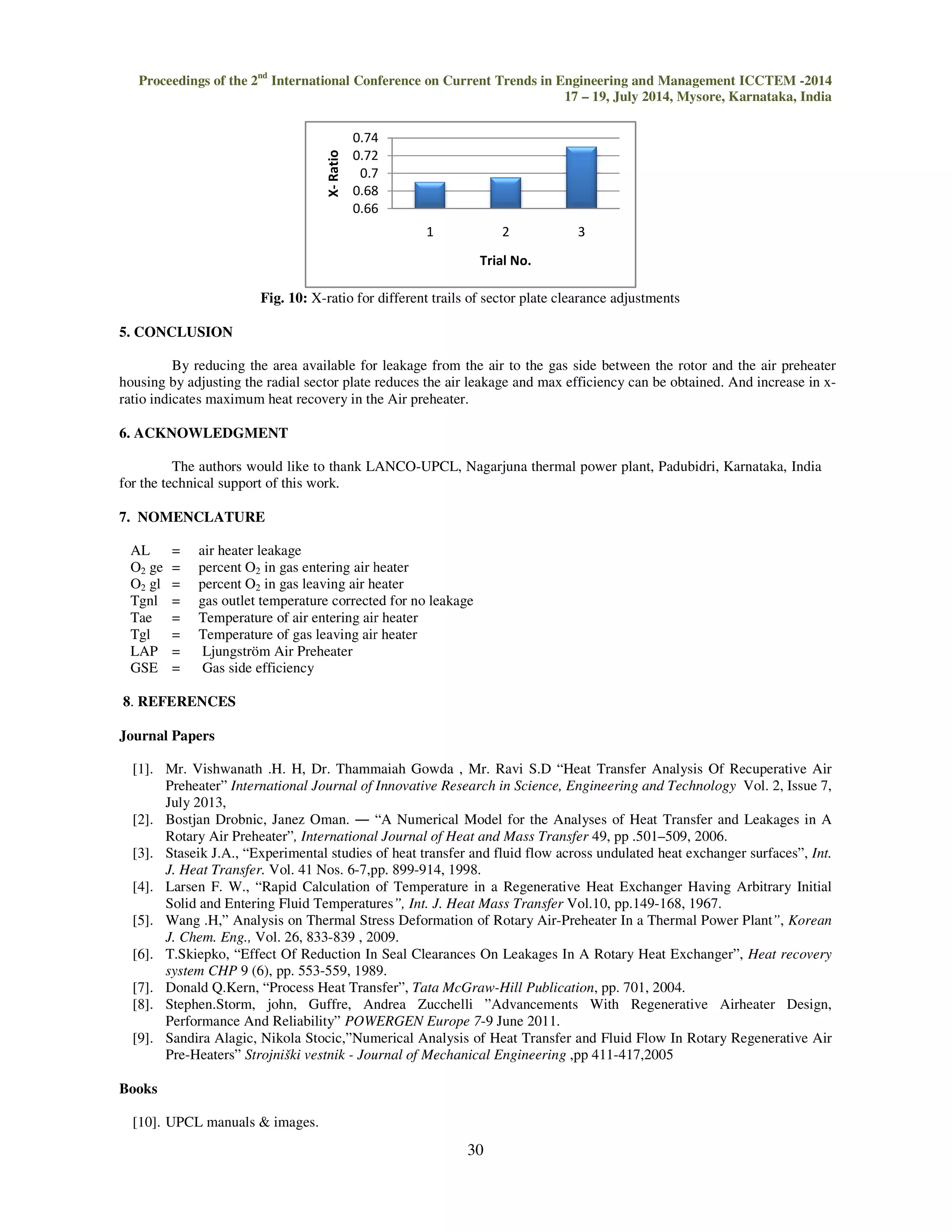
Fig 7 shows typical gas analyzer used in the test to measure oxygen percentage in the flue gas. After completing
the testing of all the ports of a air preheater, calculations can be done as per the following formulae.
Air leakage
(21 2
)
2 2
O gl
−
−
= (1)
+
=
Tgnl Tgl
100
(2)
Gas side Efficiency GSE = (Temp drop/ Temp head)*100
*100
( )
GSE
−
W out
air
W
ga sin
X− ratio =](https://image.slidesharecdn.com/performanceevaluationandoptimizationofairpreheaterinthermalpowerplant-141023093702-conversion-gate02/75/Performance-evaluation-and-optimization-of-air-preheater-in-thermal-power-plant-5-2048.jpg)

This document summarizes a study on optimizing the performance of an air preheater at a thermal power plant in India. The study evaluated the performance of a Ljungstrom air preheater (model LAP 13494/2200) before and after adjusting radial sector plate clearances. Key findings include: - Performance metrics like air leakage, gas side efficiency, and X-ratio were calculated from temperature and gas composition measurements taken at the air preheater inlet and outlet. - Adjusting the radial sector plate clearances helped reduce air leakage and improve the air preheater's gas side efficiency.


