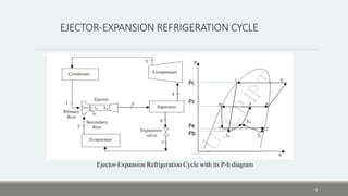
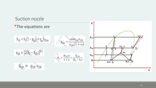
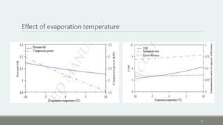
EJECTOR EXPANSION REFRIGERATION
SYSTEM
SIJO K K
S1 M-TECH
M112
1
CONTENTS
1. Introduction
2. Ejector-expansion refrigeration cycle
3. Working of EERS
4. Constant area ejector
5. working of constant area ejector
6. System analysis
7. Results and discussion
8. Conclusion
9. References
2
INTRODUCTION
•Refrigeration consumes major part of electricity
•70% systems using vapor compression
•Old and less efficient
•To overcome this difficulty high energy efficient technique should be
selected
•Use of EERS improves system performance
•Decreases compressor power
•Increase COP
•Recover expansion process by isentropic expansion process
3
EJECTOR-EXPANSION REFRIGERATION CYCLE
Ejector-Expansion Refrigeration Cycle with its P-h diagram
Pc
Ps
Pe
Pb
4
EJECTOR-EXPANSION REFRIGERATION CYCLE(cond…)
•Main parts
1) Compressor
2) Condenser
3) Two phase flow ejector
4) Separator
5) Expansion valve
6) Evaporator
•Modifications affects
1. Expansion losses
2. Suction pressure
5
WORKING OF EERC
•Compression
•Condensation
•Motive flow to ejector
•Liquid expansion in expansion device
•Evaporation (cooling)
•Secondary flow
•Mixing of flows
•Finally reaches the separator
6
CONSTANT AREA EJECTOR
Constant-area mixing ejector. a) Schematic diagram b) Pressure profile c) Velocity profile.
7
CONSTANT AREA EJECTOR
•Main parts are
1. Motive nozzle
2. Suction chamber
3. Suction nozzle
4. Constant area mixing section
5. Diffuser
8
WORKING OF CONSTANT AREA EJECTOR
•Primary flow expansion in motive nozzle (P1b=Pb < Peva)
•Secondary flow expansion to pressure (P2b=Pb)
•Mixed together to a pressure (P3m > Pb)
•Choke wave take place
•Pressure increases and velocity reduces
•Further increase of pressure in diffuser (Psep )
•Intermediate pressure
9
WORKING OF CONSTANT AREA EJECTOR
10
SYSTEM ANALYSIS
•Based on conservation of mass, energy and momentum
•Major assumptions are
a) Neglect the pressure drops in tubes ,cooler and evaporator
b) Steady state 1D flow
c) No heat loss to environment
d) Zero velocities at the inlet of both nozzles
e) Friction losses in nozzle and diffuser defined in isentropic efficiencies
f) Liquid vapor separator is 100% efficient
11
Ejector analysis
•Recovers expansion losses
•Increases compressor suction pressure
•Analysis based on conservation equations of fluid particles in
following sections
a. Motive nozzle
b. Suction nozzle
c. Mixing section
d. diffuser
12
Motive nozzle
•From P-h diagram isentropic efficiency of nozzle
•ηmn = (h1b – h1)/ (h1b, is − h1)
•Velocity at nozzle exit
•Mass flux at exit
13
Motive nozzle
•From conservation of mass area of motive stream at 1b
•Primary mass flow
•ω=ṁs / ṁp
14
Suction nozzle
•The equations are
15
Constant area mixing section
•From conservation of momentum Velocity after mixing calculated as
•Mass flux
•Applying conservation of energy, specific enthalpy given by
16
Diffuser
•Specific enthalpy at diffuser exit
•Exit isentropic specific enthalpy
ηd is the isentropic efficiency of the diffuser
17
Performance characteristics of EERS
•The cooling capacity is calculated as
•Compressor power
η com = (h 5is − h4 )/ (h5 – h4 )
•COP
18
Performance characteristics of EERS
•Pressure lift
•Ejector efficiency
hch2hb ha
19
RESULTS AND DISCUSSION
•Effect of evaporation temperature
ṁp ṁs Plift MF ω COP
20
Effect of evaporation temperature
21
Effect of condensation temperature
22
ṁp ṁs MFPlift ω COP
Effect of condensation temperature
23
CONCLUSION
•Performance of EERS is evaluated by theoretical analysis
•COP increases with increase of evaporation temp
•Compressor work decreases with increase of evaporation temp
•COP decreases with increase of condensing temp
•Compressor increases with increase of condensing temp
24
REFERENCES
1. Hassanain, M., Elgendy, E., Fatouh, M., Ejector expansion refrigeration
system: ejector design and performance evaluation, International Journal of
Refrigeration (2015) .
2. Li Zhao , Xingyang Yang , Shuai Deng , Hailong Li, Zhixin Yu. Performance
analysis of the ejector-expansion refrigeration cycle using zeotropic mixtures
International journal of refrigeration(2015)
3. Rounak Sahni ., Ejector Expansion Refrigeration Systems . International
Journal of Refrigeration (2015)
4. Ersoy, H. K., Sag, N. B., 2014. Preliminary experimental results on the R134a
refrigeration system using a two-phase ejector as an expander.
International Journal of Refrigeration. 43, 97-110.
25
REFERENCES
5. Hu, J., Shi, J., Liang, Y., Yang, Z., Chen, J., 2014. Numerical and experimental
investigation on nozzle parameters for R410A ejector air conditioning system.
International Journal of Refrigeration 40, 338-346.
6. Chaiwongsa, P., Wongwises, S., 2007. Effect of throat diameters of the ejector on the
performance of the refrigeration cycle using a two- phase ejector as an expansion
device. International Journal of Refrigeration 30, 601- 608.
7. Bilir, N., Ersoy, H., 2009. Performance improvement of the vapor compression
refrigeration cycle by a two-phase constant area ejector. International Journal of
Energy Research 33, 469–480.
8. Nehdi, E., Kairouani, L., Bouzaina, M., 2007. Performance analysis of the vapor
compression cycle using ejector as an expander. International Journal of Energy
Research 31, 364–375.
26

EJECTOR EXPANSION REFRIGERATION SYSTEM

  • 1.
  • 2.
    CONTENTS 1. Introduction 2. Ejector-expansionrefrigeration cycle 3. Working of EERS 4. Constant area ejector 5. working of constant area ejector 6. System analysis 7. Results and discussion 8. Conclusion 9. References 2
  • 3.
    INTRODUCTION •Refrigeration consumes majorpart of electricity •70% systems using vapor compression •Old and less efficient •To overcome this difficulty high energy efficient technique should be selected •Use of EERS improves system performance •Decreases compressor power •Increase COP •Recover expansion process by isentropic expansion process 3
  • 4.
    EJECTOR-EXPANSION REFRIGERATION CYCLE Ejector-ExpansionRefrigeration Cycle with its P-h diagram Pc Ps Pe Pb 4
  • 5.
    EJECTOR-EXPANSION REFRIGERATION CYCLE(cond…) •Mainparts 1) Compressor 2) Condenser 3) Two phase flow ejector 4) Separator 5) Expansion valve 6) Evaporator •Modifications affects 1. Expansion losses 2. Suction pressure 5
  • 6.
    WORKING OF EERC •Compression •Condensation •Motiveflow to ejector •Liquid expansion in expansion device •Evaporation (cooling) •Secondary flow •Mixing of flows •Finally reaches the separator 6
  • 7.
    CONSTANT AREA EJECTOR Constant-areamixing ejector. a) Schematic diagram b) Pressure profile c) Velocity profile. 7
  • 8.
    CONSTANT AREA EJECTOR •Mainparts are 1. Motive nozzle 2. Suction chamber 3. Suction nozzle 4. Constant area mixing section 5. Diffuser 8
  • 9.
    WORKING OF CONSTANTAREA EJECTOR •Primary flow expansion in motive nozzle (P1b=Pb < Peva) •Secondary flow expansion to pressure (P2b=Pb) •Mixed together to a pressure (P3m > Pb) •Choke wave take place •Pressure increases and velocity reduces •Further increase of pressure in diffuser (Psep ) •Intermediate pressure 9
  • 10.
    WORKING OF CONSTANTAREA EJECTOR 10
  • 11.
    SYSTEM ANALYSIS •Based onconservation of mass, energy and momentum •Major assumptions are a) Neglect the pressure drops in tubes ,cooler and evaporator b) Steady state 1D flow c) No heat loss to environment d) Zero velocities at the inlet of both nozzles e) Friction losses in nozzle and diffuser defined in isentropic efficiencies f) Liquid vapor separator is 100% efficient 11
  • 12.
    Ejector analysis •Recovers expansionlosses •Increases compressor suction pressure •Analysis based on conservation equations of fluid particles in following sections a. Motive nozzle b. Suction nozzle c. Mixing section d. diffuser 12
  • 13.
    Motive nozzle •From P-hdiagram isentropic efficiency of nozzle •ηmn = (h1b – h1)/ (h1b, is − h1) •Velocity at nozzle exit •Mass flux at exit 13
  • 14.
    Motive nozzle •From conservationof mass area of motive stream at 1b •Primary mass flow •ω=ṁs / ṁp 14
  • 15.
  • 16.
    Constant area mixingsection •From conservation of momentum Velocity after mixing calculated as •Mass flux •Applying conservation of energy, specific enthalpy given by 16
  • 17.
    Diffuser •Specific enthalpy atdiffuser exit •Exit isentropic specific enthalpy ηd is the isentropic efficiency of the diffuser 17
  • 18.
    Performance characteristics ofEERS •The cooling capacity is calculated as •Compressor power η com = (h 5is − h4 )/ (h5 – h4 ) •COP 18
  • 19.
    Performance characteristics ofEERS •Pressure lift •Ejector efficiency hch2hb ha 19
  • 20.
    RESULTS AND DISCUSSION •Effectof evaporation temperature ṁp ṁs Plift MF ω COP 20
  • 21.
    Effect of evaporationtemperature 21
  • 22.
    Effect of condensationtemperature 22 ṁp ṁs MFPlift ω COP
  • 23.
    Effect of condensationtemperature 23
  • 24.
    CONCLUSION •Performance of EERSis evaluated by theoretical analysis •COP increases with increase of evaporation temp •Compressor work decreases with increase of evaporation temp •COP decreases with increase of condensing temp •Compressor increases with increase of condensing temp 24
  • 25.
    REFERENCES 1. Hassanain, M.,Elgendy, E., Fatouh, M., Ejector expansion refrigeration system: ejector design and performance evaluation, International Journal of Refrigeration (2015) . 2. Li Zhao , Xingyang Yang , Shuai Deng , Hailong Li, Zhixin Yu. Performance analysis of the ejector-expansion refrigeration cycle using zeotropic mixtures International journal of refrigeration(2015) 3. Rounak Sahni ., Ejector Expansion Refrigeration Systems . International Journal of Refrigeration (2015) 4. Ersoy, H. K., Sag, N. B., 2014. Preliminary experimental results on the R134a refrigeration system using a two-phase ejector as an expander. International Journal of Refrigeration. 43, 97-110. 25
  • 26.
    REFERENCES 5. Hu, J.,Shi, J., Liang, Y., Yang, Z., Chen, J., 2014. Numerical and experimental investigation on nozzle parameters for R410A ejector air conditioning system. International Journal of Refrigeration 40, 338-346. 6. Chaiwongsa, P., Wongwises, S., 2007. Effect of throat diameters of the ejector on the performance of the refrigeration cycle using a two- phase ejector as an expansion device. International Journal of Refrigeration 30, 601- 608. 7. Bilir, N., Ersoy, H., 2009. Performance improvement of the vapor compression refrigeration cycle by a two-phase constant area ejector. International Journal of Energy Research 33, 469–480. 8. Nehdi, E., Kairouani, L., Bouzaina, M., 2007. Performance analysis of the vapor compression cycle using ejector as an expander. International Journal of Energy Research 31, 364–375. 26