Downloaded 342 times


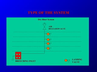

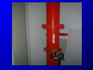


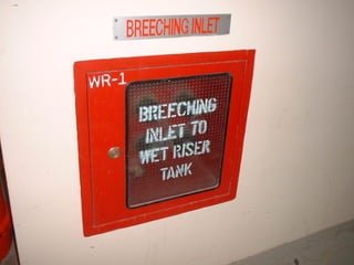
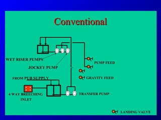

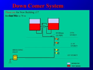
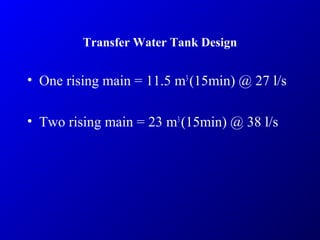
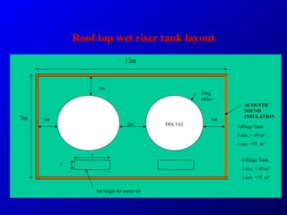

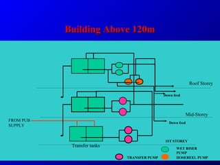


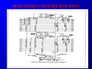


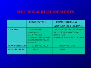
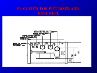
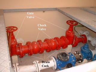
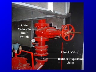

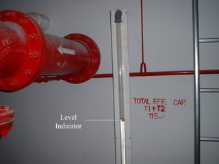
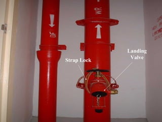
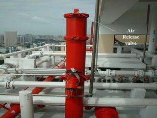

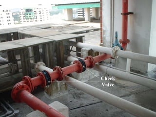
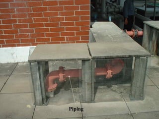
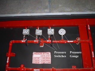
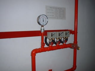
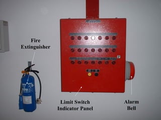

This document provides information on wet and dry riser firefighting systems, including design criteria, requirements, and system components. It discusses factors like building height and area that determine the number and size of rising mains. Key elements of wet riser systems are described such as breeching inlets, landing valves, air release valves, pump configurations, and tank capacities. Requirements for submission to authorities are also covered.


![[Deck] What's New in Spark-Iceberg Integration via DSV2.pptx](https://cdn.slidesharecdn.com/ss_thumbnails/deckwhatsnewinspark-icebergintegrationviadsv2-260210005337-25955b12-thumbnail.jpg?width=640&height=640&fit=bounds)


