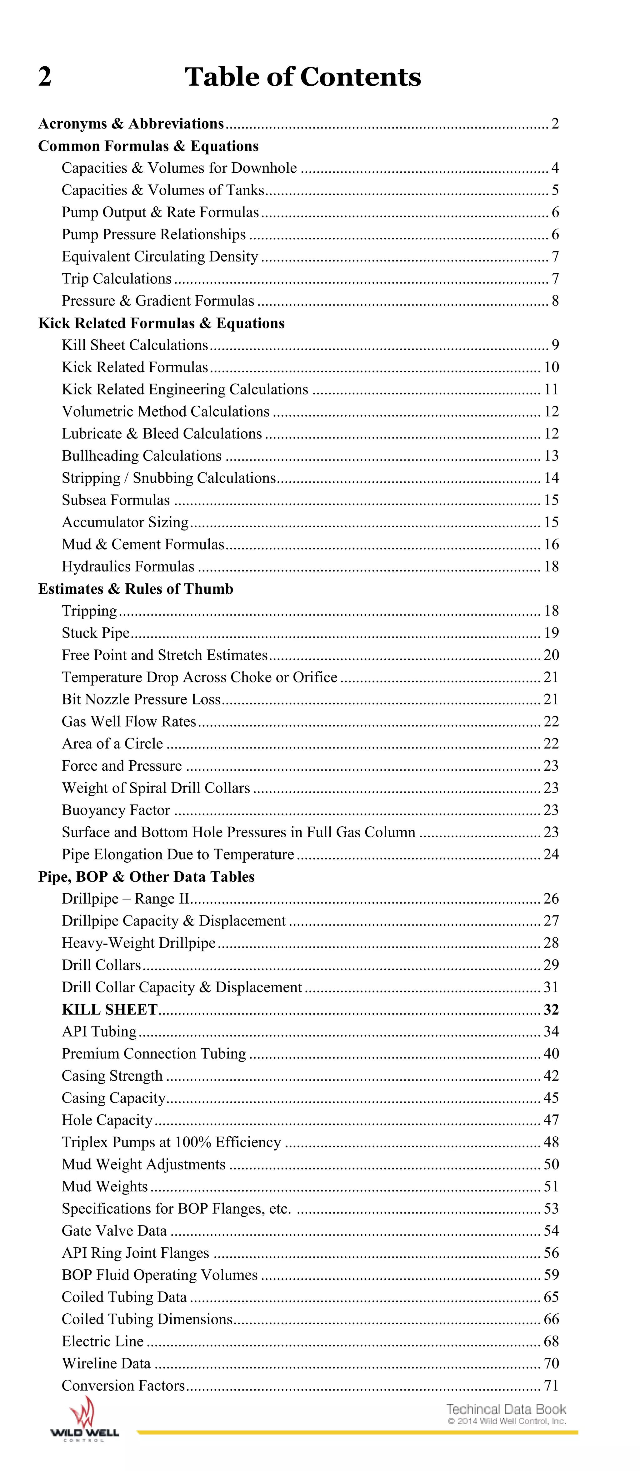
This document provides technical data and formulas for Wild Well's oilfield services. It includes formulas for calculating capacities and volumes, pump outputs and pressures, equivalent circulating density, trip calculations, pressure and gradients, kick sheet calculations, and tables of pipe, casing, and BOP specifications. Wild Well offers a wide range of well control, engineering, and training services to safely address complex issues in the oil and gas industry.


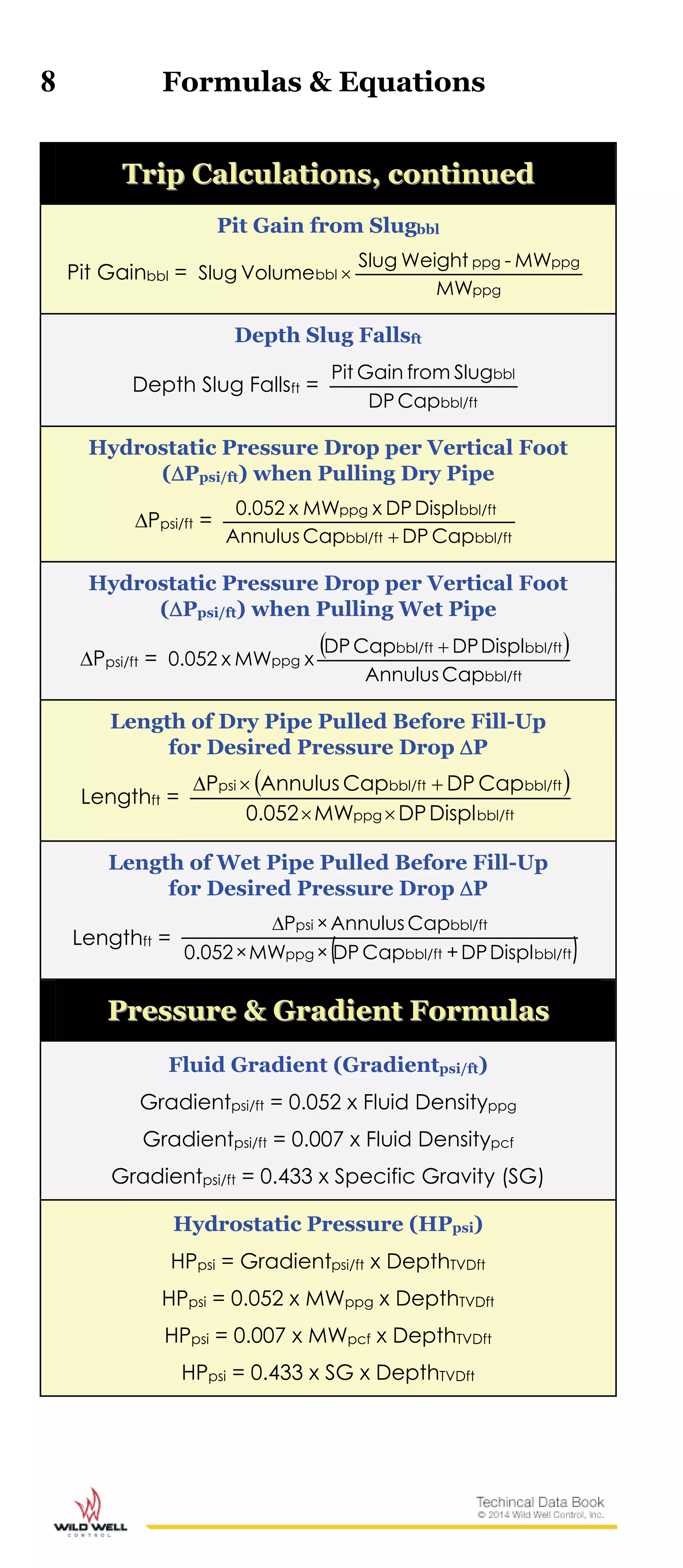
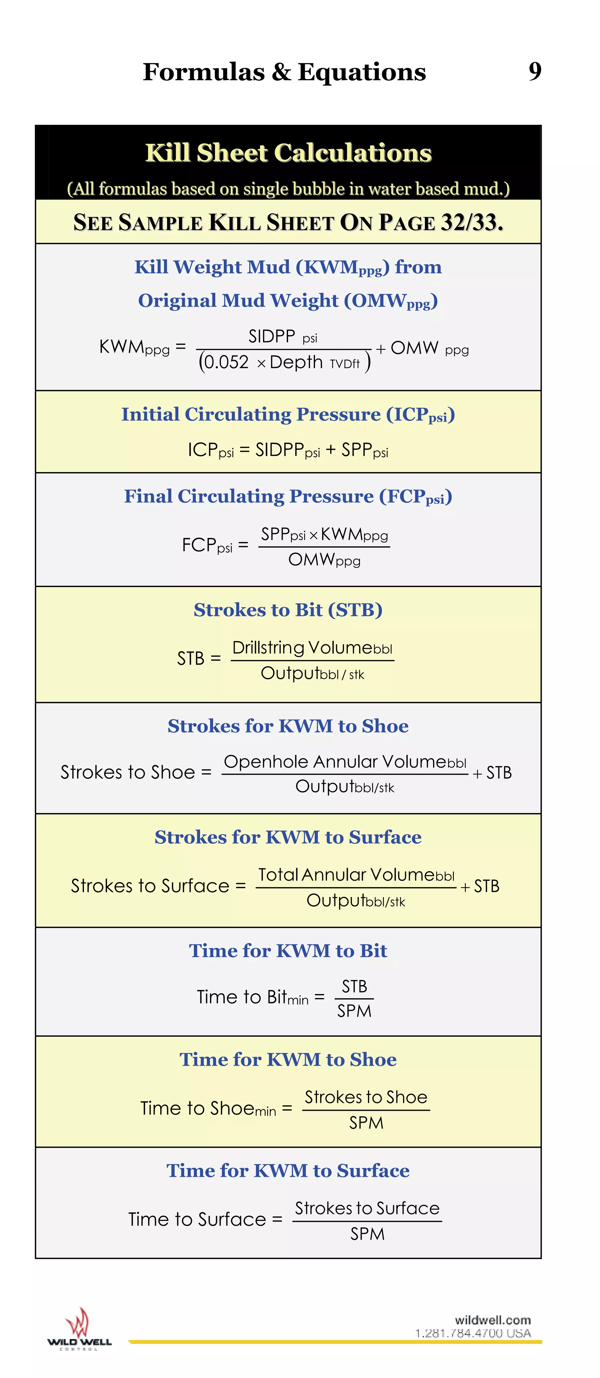
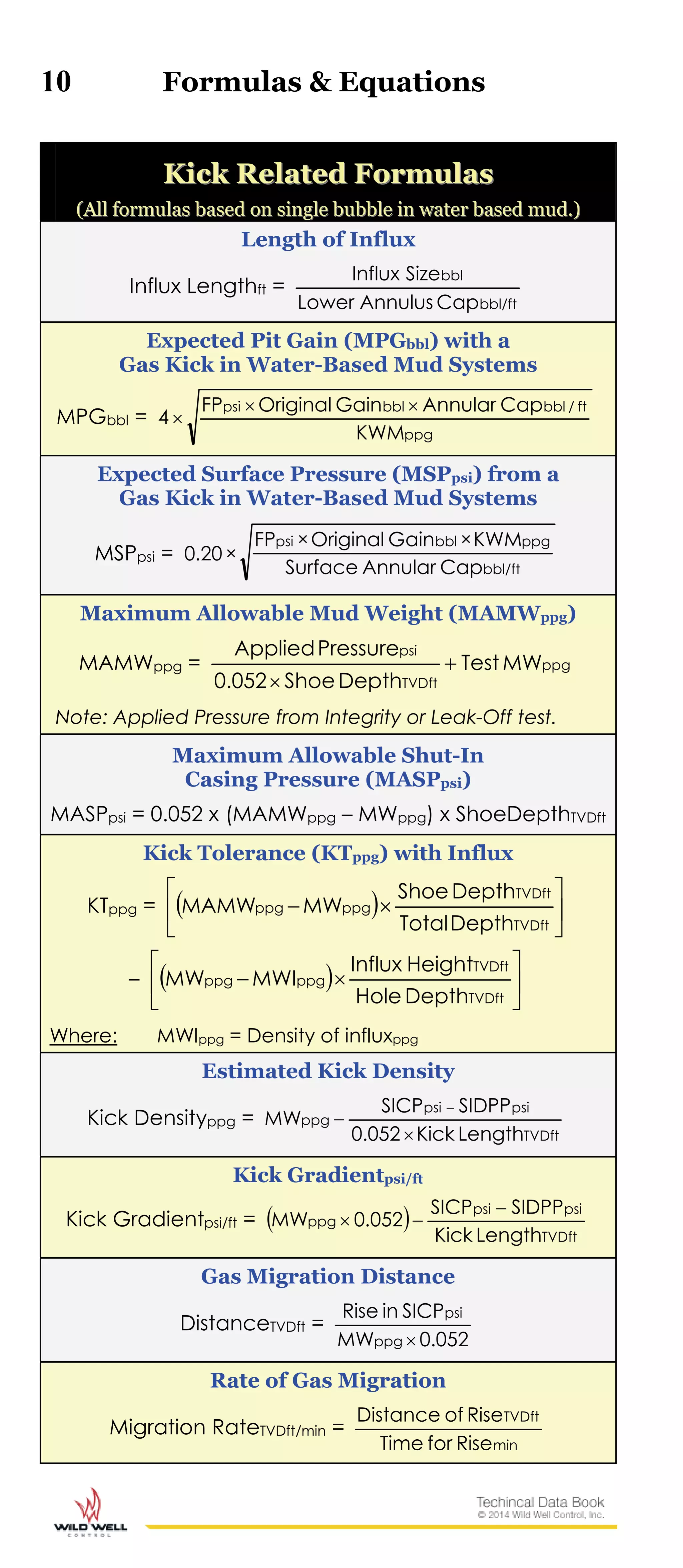
![6 Formulas & Equations
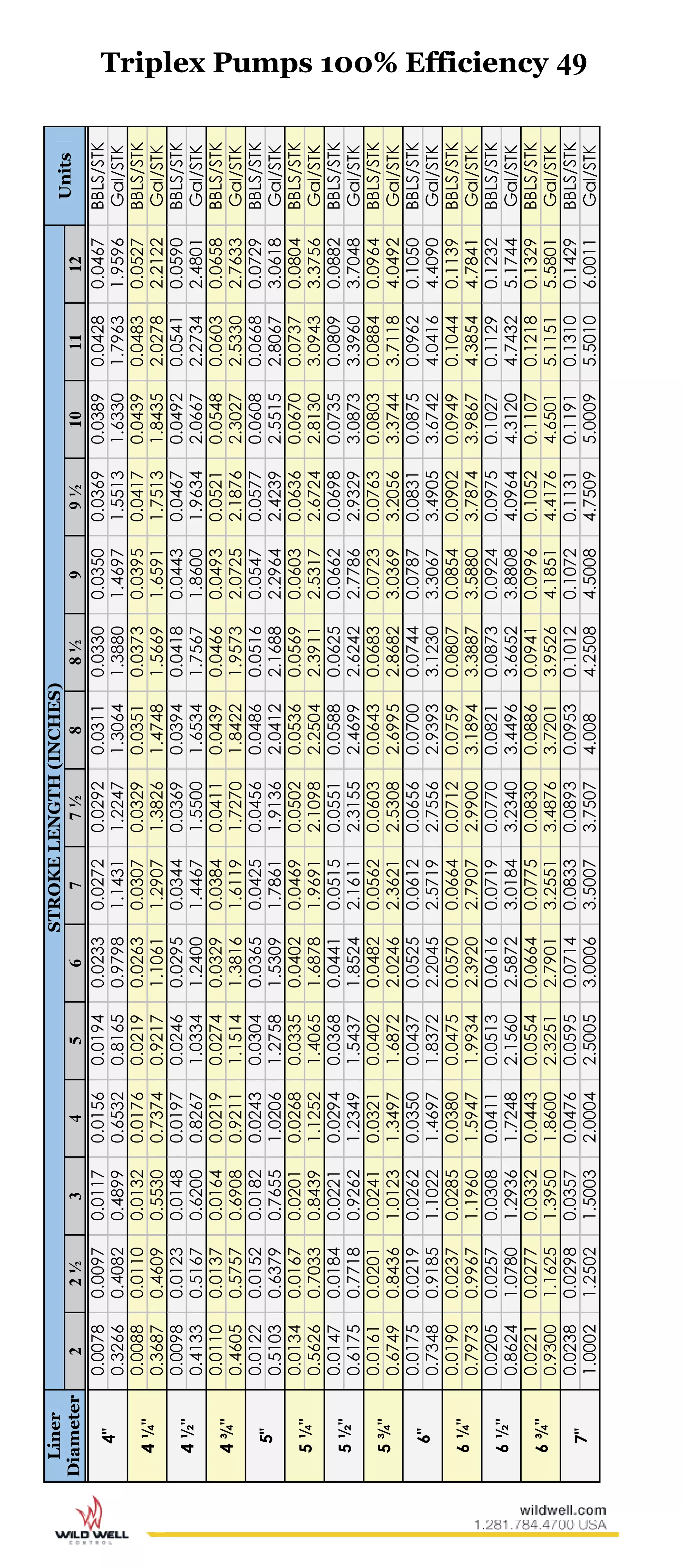
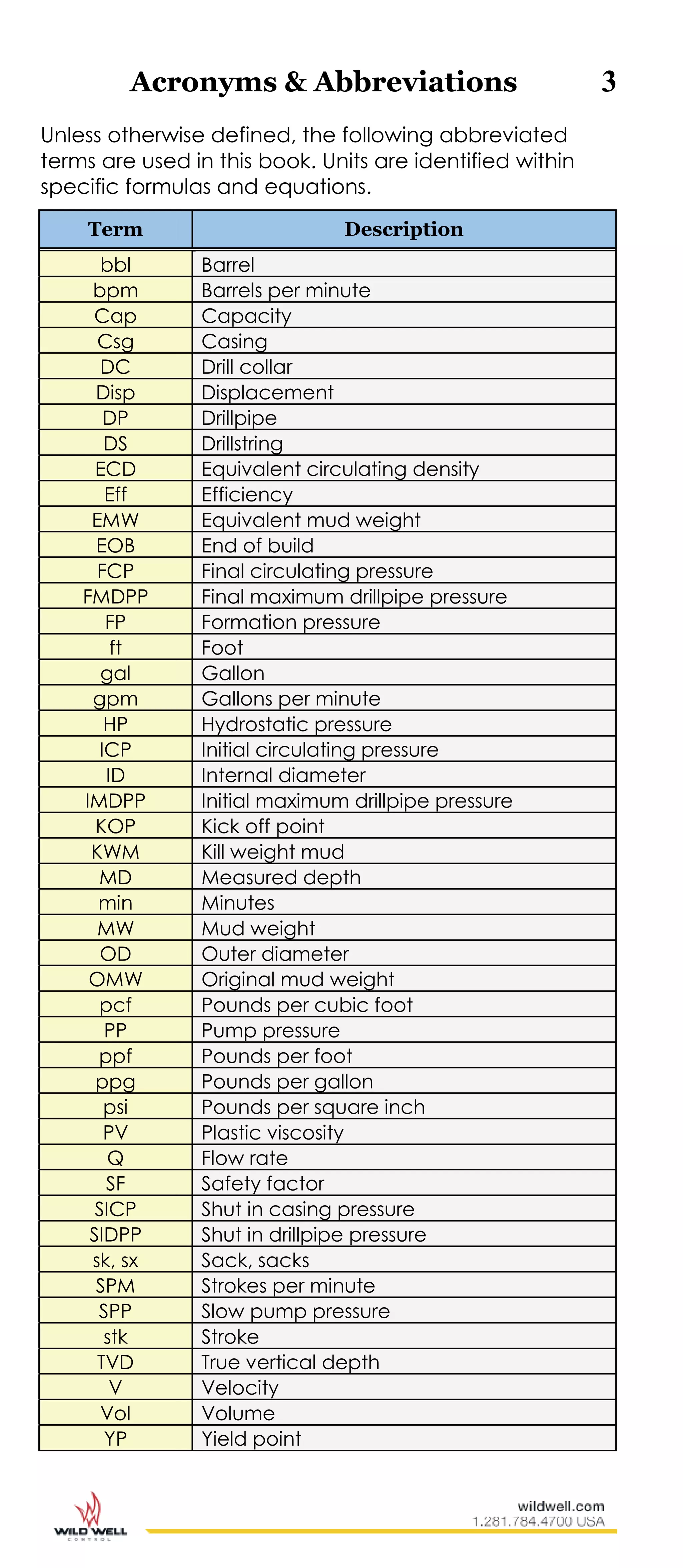
PPuummpp OOuuttppuutt && RRaattee FFoorrmmuullaass
Pump Outputs
FOR TRIPLEX PUMPS:
Outputbbl/stk =
0.000243 x (Liner IDinches)2 x Strokeinches x Eff%
FOR DUPLEX PUMPS (DOUBLE ACTING):
Outputbbl/stk =
0.000162 x [2 x (Liner IDinches)2 – (Rod ODinches)2]
x Strokeinches x Eff%
Pump Rates
Ratebpm = Outputbbl/stk x SPM
Rategpm = 42 x Outputbbl/stk x SPM
Pumping/Spotting/Displacing
Timemin =
SPMOutput
PumptoBBL
bbl/stk
PPuummpp PPrreessssuurree RReellaattiioonnsshhiippss
New Pump Pressure (PP) for Rate Change
New PPpsi = psi
bpm
bpm
PPOld
RateOld
RateNew
2
New PPpsi = psiPPOld
SPMOld
SPMNew
2
New Pump Pressure (PP) for Density Change
New PPpsi = psi
ppg
ppg
PPOriginal
MWOriginal
MWNew
](https://image.slidesharecdn.com/technical-data-book-150913130222-lva1-app6892/75/Technical-data-book-8-2048.jpg)
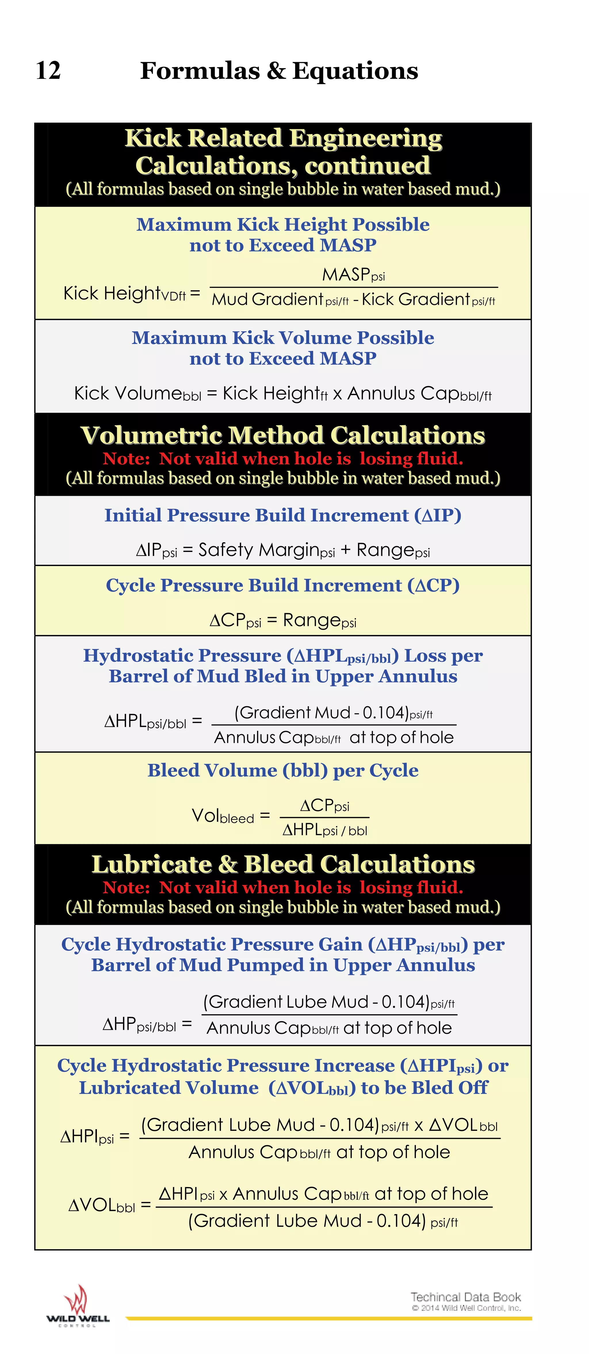
![Formulas & Equations 11
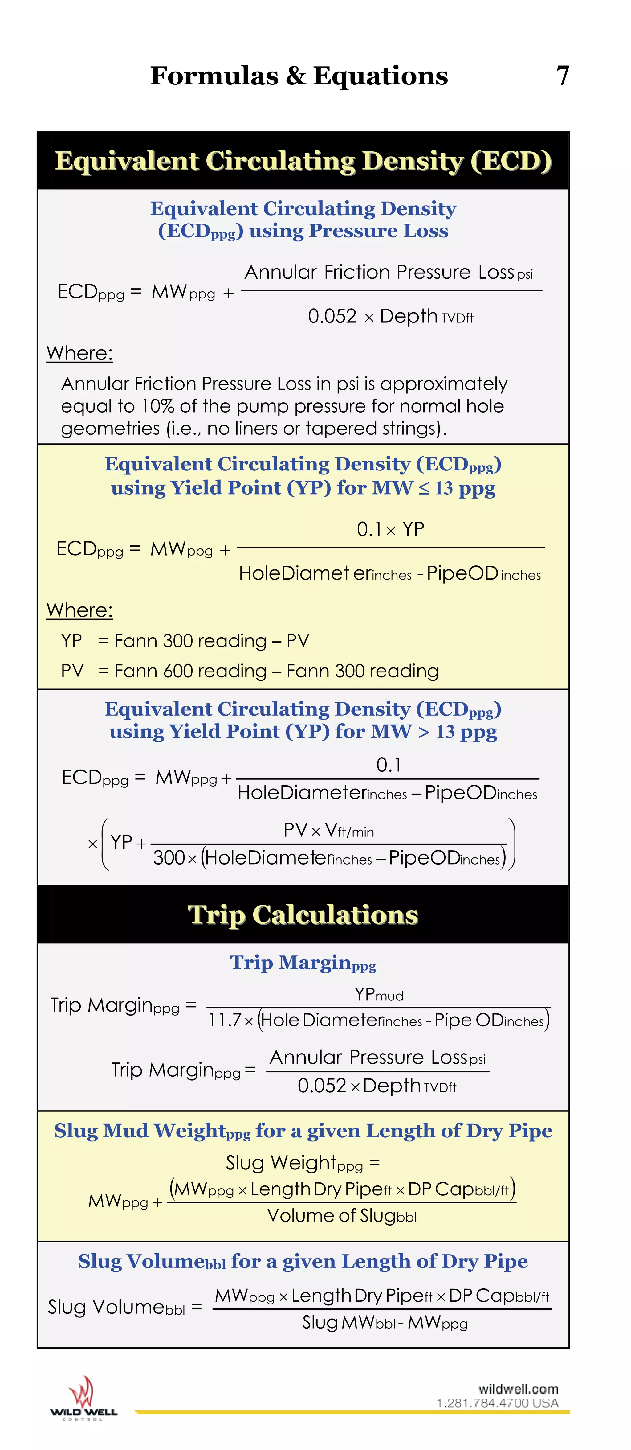
KKiicckk RReellaatteedd EEnnggiinneeeerriinngg
((AAllll ffoorrmmuullaass bbaasseedd oonn ssiinnggllee bbuubbbbllee iinn wwaatteerr bbaasseedd mmuudd..))
Bottom Hole Pressure (BHPpsi) while
Circulating on the Choke
BHPpsi = Hydrostatic Pressurepsi Mud in Drillstring
+ SIDPPpsi
Equivalent Mud Weight (EMWppg) at Bottom Hole
while Circulating out a Kick
EMWppg =
TVDft
psi
Depth0.052
BHP
Shut-In Casing Pressure (SICPpsi)
SICPpsi = ppgppgpsi DensityKickMW052.0[SIDPP
x Length of InfluxVDft
Formation Pressure (FPpsi)
FPpsi = SIDPPpsi + [0.052 x OMWppg x DepthTVDft]
FPpsi = SICP + 0.052 x [(Kick LengthVDft x Kick Densityppg)
+ (Mud Columnft x OMWppg)]
% Reduction in Hydrostatic Pressure Due to Gas-
Cut Mud (GCMW) %Pgcm (for water-base mud)
%Pgcm =
ppg
ppgppg
GCMW
GCMWOMW100
Leak-Off Test Pressure (LOTpsi) and
Equivalent Mud Weight (EMWLOT) at Shoe
LOTpsi = 0.052 x Test MWppg x TVDshoe
+ Applied Pressure to Leak-Offpsi
EMWLOT ppg =
TVDft
psi
ShoeDepthx0.052
LOT
Formation Integrity Test Pressure (FITpsi) and
Equivalent Mud Weight (EMWFIT) at Shoe
FITpsi = 0.052 x Test MWppg x TVDshoe
+ Applied Integrity Pressurepsi
EMWFIT ppg =
TVDft
psi
ShoeDepthx0.052
FIT
Maximum Formation Pressure that can
be Controlled with a Well Shut-In
Max FPpsi = 0.052 x (KTppg + MWppg) x DepthTVDft](https://image.slidesharecdn.com/technical-data-book-150913130222-lva1-app6892/75/Technical-data-book-13-2048.jpg)