Circulating System
The circulatingsystem is used to circulate drilling
fluid down through the drill string and up the
annulus, carrying the drilled cuttings from the face
of the bit to surface.
3.
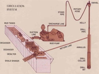
Circulating system consistof the following:
1. Mud Pump 7. Return Line
2. Discharge line 8. Shale Shaker
3. Standpipe 9. Desander
4. Swivel 10. Desilter
5. Drill pipe 11. Degasser
6. Annulus 12. Mud Pit
5.
Circulating System
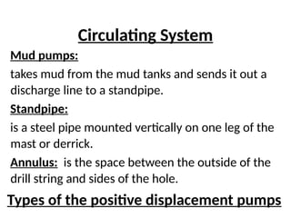
Mud pumps:
takesmud from the mud tanks and sends it out a
discharge line to a standpipe.
Standpipe:
is a steel pipe mounted vertically on one leg of the
mast or derrick.
Annulus: is the space between the outside of the
drill string and sides of the hole.
Types of the positive displacement pumps
6.
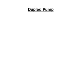
The heart ofthe circulating system is the mud
pumps.
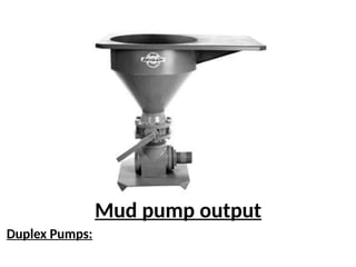
There are two types of PDP:
• Duplex (2 cylinders)
• Triplex (3 cylinders)
• Triplex PDPs, due to several advantages, (less
bulky, less pressure fluctuation, cheaper to buy
and to maintain, etc,) has taking place of the
duplex PDPs in both onshore and offshore rigs.
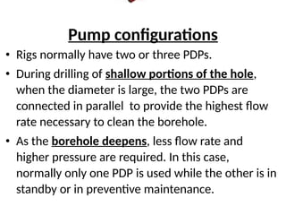
Pump configurations
• Rigsnormally have two or three PDPs.
• During drilling of shallow portions of the hole,
when the diameter is large, the two PDPs are
connected in parallel to provide the highest flow
rate necessary to clean the borehole.
• As the borehole deepens, less flow rate and
higher pressure are required. In this case,
normally only one PDP is used while the other is in
standby or in preventive maintenance.
11.
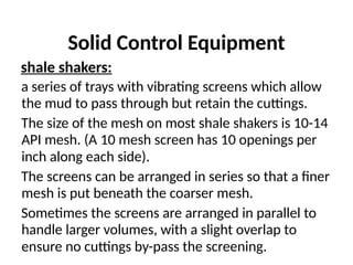
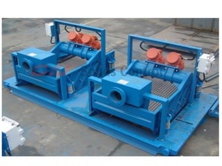
Solid Control Equipment
shaleshakers:
a series of trays with vibrating screens which allow
the mud to pass through but retain the cuttings.
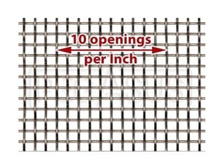
The size of the mesh on most shale shakers is 10-14
API mesh. (A 10 mesh screen has 10 openings per
inch along each side).
The screens can be arranged in series so that a finer
mesh is put beneath the coarser mesh.
Sometimes the screens are arranged in parallel to
handle larger volumes, with a slight overlap to
ensure no cuttings by-pass the screening.
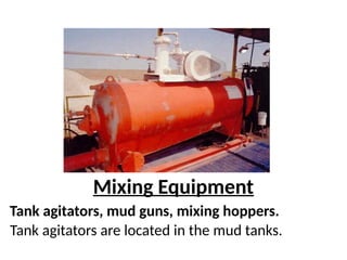
Auxiliary Equipment
Several piecesof auxiliary equipment keep the
mud in good shape.
After the mud passes through the shale shaker, it
sifts out the normal-sized cuttings.
Then the system sends the mud through:
• Desanders;
• Desilters;
• mud cleaners;
• mud centrifuges.
16.
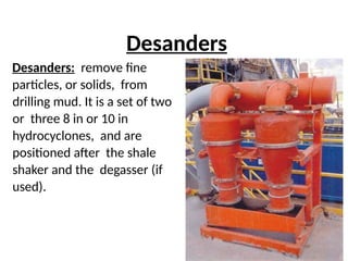
Desanders
Desanders: remove fine
particles,or solids, from
drilling mud. It is a set of two
or three 8 in or 10 in
hydrocyclones, and are
positioned after the shale
shaker and the degasser (if
used).
17.
Desilters
A set of(8 to 12) 4 in or 5in hydrocyclones.
It removes particles that can not be removed
by the desander.
18.
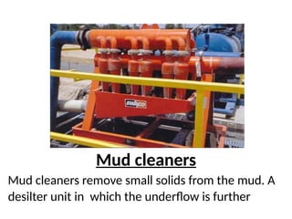
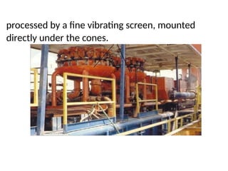
Mud cleaners
Mud cleanersremove small solids from the mud. A
desilter unit in which the underflow is further
19.
processed by afine vibrating screen, mounted
directly under the cones.
20.
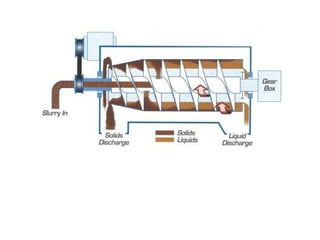
Mud Centrifuge
The centrifugeis a solids control equipment
which separates particles even smaller, which
can not be removed by the hydrocyclones.
22.
Degasser
A degasser removessmall amounts of gas
that enter the drilling mud as it circulates
past a formation that contains gas.
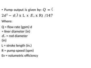
• Pump outputis given by: 𝑄 =
2𝑑2
− 𝑑𝑟 x L 𝑥 𝐸𝑣 x R) /147
Where:
Q = flow rate (gpm) d
= liner diameter (in)
𝑑𝑟 = rod diameter
(in)
L = stroke length (in.)
R = pump speed (spm)
Ev = volumetric efficiency
29.
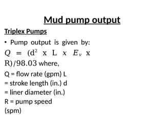
Mud pump output
TriplexPumps
• Pump output is given by:
𝑄 = (d2
x L 𝑥 𝐸𝑣 x
R)/98.03 where,
Q = flow rate (gpm) L
= stroke length (in.) d
= liner diameter (in.)
R = pump speed
(spm)
30.
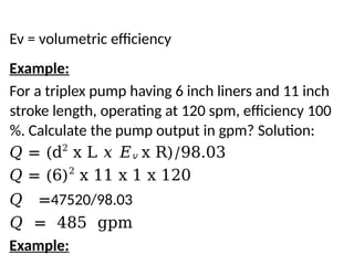
Ev = volumetricefficiency
Example:
For a triplex pump having 6 inch liners and 11 inch
stroke length, operating at 120 spm, efficiency 100
%. Calculate the pump output in gpm? Solution:
𝑄 = (d2
x L 𝑥 𝐸𝑣 x R)/98.03
𝑄 = (6)2
x 11 x 1 x 120
𝑄 =47520/98.03
𝑄 = 485 gpm
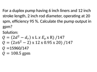
Example:
31.
For a duplexpump having 6 inch liners and 12 inch
stroke length, 2 inch rod diameter, operating at 20
spm, efficiency 95 %. Calculate the pump output in
gpm?
Solution:
32.
The Drillstring
The drillstring is the mechanical linkage connecting
the drillbit at the bottom of the hole to the rotary
drive system on the surface.
The functions of the drill string are:
• To suspend the bit
• To transmit rotary torque from the kelly to the bit
• To provide a conduit for circulating drilling fluid to
the bit
Components of the drillstring
33.
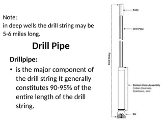
Note:
in deep wellsthe drill string may be
5-6 miles long.
Drill Pipe
Drillpipe:
• is the major component of
the drill string It generally
constitutes 90-95% of the
entire length of the drill
string.
34.
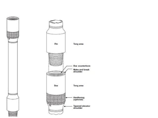
• Drill pipeis a seamless pipe with threaded
connections, known as tool joints
• At one end of the pipe there is the box, and at
the other end of each length of drill pipe there
is a pin.
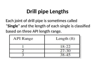
Drill pipe Lengths
Eachjoint of drill pipe is sometimes called
“Single” and the length of each single is classified
based on three API length range.
38.
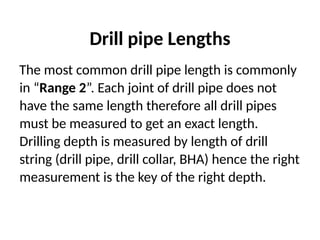
Drill pipe Lengths
Themost common drill pipe length is commonly
in “Range 2”. Each joint of drill pipe does not
have the same length therefore all drill pipes
must be measured to get an exact length.
Drilling depth is measured by length of drill
string (drill pipe, drill collar, BHA) hence the right
measurement is the key of the right depth.
39.
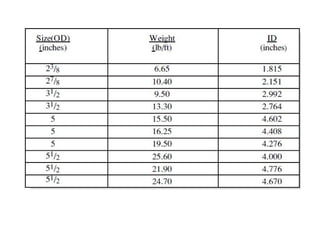
Dimensions of Drillpipe
The drill pipe is manufactured in a variety of
outside diameters, and weights.
41.
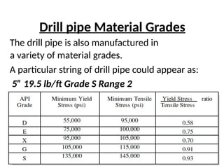
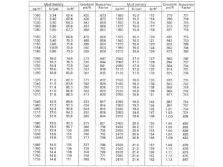
Drill pipe MaterialGrades
The drill pipe is also manufactured in
a variety of material grades.
A particular string of drill pipe could appear as:
5” 19.5 lb/ft Grade S Range 2
42.
Drill Pipe Classification
Drillpipe class defines the physical condition of the drill
pipe in terms of dimension, surface damage, and corrosion.
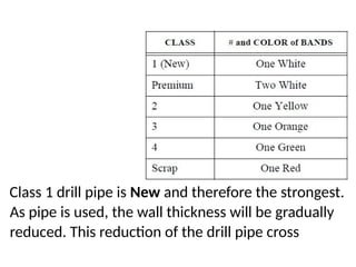
Drill pipe class is indicated by paint bands on the drill pipe
according to the following code:
43.
Class 1 drillpipe is New and therefore the strongest.
As pipe is used, the wall thickness will be gradually
reduced. This reduction of the drill pipe cross
Drill pipe weight
•The weight shown in the table of Dimensions of
drill pipe is (“Weight in air”).
• When the pipe is suspended in the borehole it
will be immersed in drilling fluid; and will
therefore be subjected to a buoyant force. The
weight of drill pipe in a fluid (“Wet Weight”)
calculated as:
Buoyant Weight (“Wet Weight”) of Drill pipe
= Weight of pipe in Air x Buoyancy Factor
47.
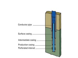
Well Completion
Well completionmeans to prepare
the well for production by installing
the necessary equipments into the
well in order to allow the safe and
controlled flow of hydrocarbons at
the surface.
48.
Introduction - Casing
Whatis casing?
Casing is a steel tube that starts from the
surface and goes down to the bottom of the
hole, and is rigidly connected to the rocky
formation using cement slurry.
• casing string is made up of joints of pipe,
of approximately 40 ft in length.
49.
• The costof the casing can therefore
constitute 2030% of the total cost of the
well.
1. Conductor Casing(30”
O.D.)
Functions
• to protect near surface unconsolidated
formations;
• to seal off shallow-water zones;
• to provide a circuit for the drilling mud ;
• to protect the foundations of the platform.
53.
Setting depth
• fromthe surface to some shallow depth
(≈100 ft)
2. Surface Casing (20” O.D.)
Functions
• to seal off any fresh water sands,
• support the wellhead and BOP equipment.
• to prevent caving of weak formations that are
encountered at shallow depths.
54.
• to ensurethat the formations at the casing shoe
will not fracture at high hydrostatic pressures
which maybe used later.
Setting depth
The surface casing is run after the conductor and is
generally set at approximately 1000 - 1500 ft below
the ground level
3. Intermediate Casing (13 3/8”
O.D.)
Functions
• to seal off a severe-loss zones;
55.
• to protectproblem formations, such as salt
sections or caving shales;
• to prevent communication behind the
casing between the lower hydrocarbon
zones and upper water formations.
Setting depth
• usually set in the transition zone below or
above an over-pressured zone
56.
4. Production Casing(9 5/8”
O.D.)
Functions
• to isolate producing zones;
• to provide reservoir fluid control
• to permit selective production in multi-
zone production.
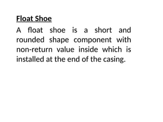
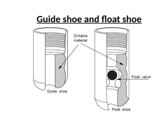
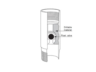
Downhole cementing
equipment
Float collar
•A float collar is positioned 1 or 2 joints
above the guide shoe.
• It acts as a seat for the cement plugs
used in the pumping and displacement of
the cement slurry.
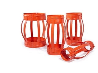
Downhole cementing equipment
Centralisers
Acentralizer is a device to keep a
casing string out of the well bore wall.
The spacing of centralisers will vary
depending on the requirements of
each cement job.
A typical programfor
centraliser
1 centraliser immediately above the
shoe
1 every joint on the bottom 3 joints
1 every joint through the production
zone
67.
1 every 3joints elsewhere
Downhole cementing equipment
Wipers/scratchers
These are devices run on the outside of the
casing to remove mud cake and break up
gelled mud. They are sometimes used
through the production zone.
69.
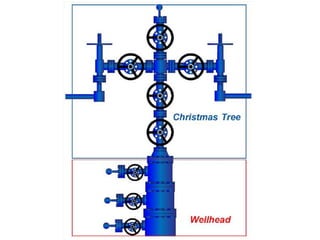
Installing the ChristmasTree
• A collection of valves called a Christmas tree
is installed on the surface at the top of the
casing hanger.
• As the well’s production flows up the
tubing, it enters the Christmas tree.
• So, the production can be controlled by
opening or closing valves on the Christmas
tree.
Function of Christmastree
• Allow reservoir fluid to flow from the well
to the surface safely in a controlled manner.
• Allow safe access to the wellbore in order
to perform well intervention procedures.
• Allow injections as water or gas injection.
• Provide electrical equipment for electrical
submersible pump.
73.
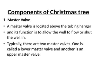
Components of Christmastree
1. Master Valve
• A master valve is located above the tubing hanger
• and its function is to allow the well to flow or shut
the well in.
• Typically, there are two master valves. One is
called a lower master valve and another is an
upper master valve.
74.
• Two valvesare often used because they provide
redundancy. If one master valve cannot function
properly, another valve can perform the function.
Components of Christmastree
2. T type fitting (T-Block)
T type fitting (T-Block) allows diversion of
flow stream from vertical to a horizontal
flow line.
Components of Christmastree
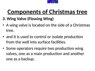
3. Wing Valve (Flowing Wing)
• A wing valve is located on the side of a Christmas
tree.
• and it is used to control or isolate production
from the well into surface facilities.
• Some operators require two production wing
valves, one as a main production and another
one as a backup.
79.
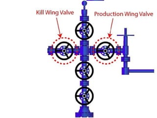
• In manycases, one wing valve is used for
production and another wing valve is used as a
kill wing valve.
Components of Christmastree
4. Choke
Choke is the smallest restriction in a
Christmas tree, and its function is to control
the production rate of a well.
Components of Christmastree
5. Swab Valve
On a Christmas tree, a swab valve is the
topmost valve providing vertical access to the
well for well intervention operations.
Components of Christmastree
6. T-Cap and Pressure Gauge
• T-Cap is a flange located on top of the swab
valve which allows a snubbing unit to
connect to a well in order to perform well
intervention programs.
• A pressure gauge is used to monitor the
pressure of the well.