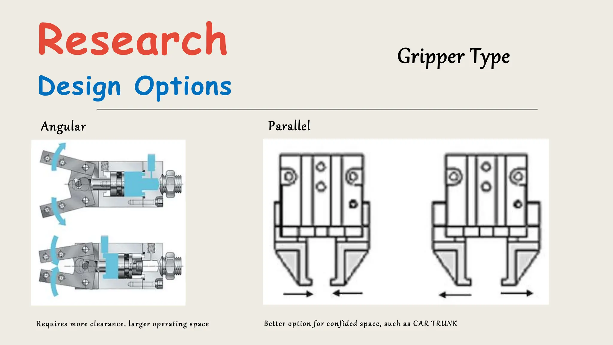
Project Objective
• Designagripperforarobotthatcanefficiently,effectivelyandsafelygraspa
sparetireassemblyfromarackandinsertitintothetrunkofa2018Honda
Civic
Desig
n
Goals
Identification of
need
• Achieve the finishing process efficiently
• Shorten the processingtime
• Ensure the consistencyof processingquality
• Reduce Complexity
• Reduce Maintenance by reducedparts
• Optimized design
Market
Research
Commonly used Grippers
Research
Identifying Problem
• Very Large
• Heavy and complex
• Versatile but underutilized
• High Maintenance
• Expensive
Research
Design Options
Why Pneumatic Sysytems?
TheycanquicklymeetMechanical
Safetyrequirements
Suitablefor applicationsrequiring
repeatedoperations
A pneumaticactuatoris cost-effective
andrequireslittleto no maintenance
Comparedto a hydraulicactuator,the
pneumaticone offershigh-speed
motion
Research
Design Options
Gripper Type
Angular Parallel
Requires more clearance, larger operating space Better option for confided space, such as CAR TRUNK
Research
Design Options
Finger Type
Encompassing, Friction, Retention
Friction Gripper is least complicated, versatile and works well on spaces with small clearance
Design Considerations
Assumptions & Workpiece Specifications
Specifications:-
1. Car considered as model: 2018 Honda Civic
2. Spare tire size: T125/70R17
Assumptions:-
1. Tire is laying flat on the rack
2. General safety always is part of Robotic applications, in case of failure, there is a
safety-fail mechanism
Design Considerations
Six Factors
1.Gripping force:
• The gripper must be designed to provide sufficient gripping force to securely hold the spare wheel in place during
installation
• The gripping force required will depend on the weight and size of the spare wheel
2.Gripping mechanism:
• The gripper mechanism must be designed to securely grip the spare wheel without damaging it
• This could involve using a specific type of gripper, such as a pneumatic gripper
3.Size and shape:
• The gripper must be designed to accommodate the size and shape of the spare wheel used in the Honda Civic
Design Considerations
Six Factors
4.Compatibility:
• The gripper must be designed to be compatible with the robotic system used for the Honda Civic assembly line
• Involves ensuring that the gripper can be easily integrated into the existing system and that it can be programmed to perform the
required tasks
5.Safety:
• Incorporating safety features such as sensors to detect obstacles or emergency stop mechanisms
• Check valves to Maintain grip ing case of reduced pressure
6. Maintenance and durability:
• Designed to be durable and require minimal maintenance
• This By using materials that are resistant to wear and tear
Standard parts available for replacement
Design Considerations
Gripping Force
The gripping force is calculated as the minimum force required to prevent the workpiece from slipping when it is held by fric tion.
𝐹 ≥
𝑚 × 𝑔 × 𝑎
𝑛 × 𝜇
× 𝑆 ≥ 257.512 𝑁
m = 14 Kg
g = 9.81 m/s2
a = 1 m/s2 (Acceleration of robot arm)
n = 2 (number of jaws)
μ = 0.8 (Friction co - efficient steel & Rubber)
S.F = 3 (Factor of Safety)
Conceptualization
Bayesian Model
Decision Tree
Problem Structure
• Assessing the probability of successful grasping and insertion based on various design factors such as grip type, gripping
force, and gripper size etc.
• Use problem structuring to identify any potential issues or constraints that may arise during the design process
• These may include limitations on available materials, regulatory requirements for workplace safety, and the need for
compatibility with existing robotic systems in the assembly line
• Use a decision tree to identify the most appropriate gripping mechanism based on the shape and weight distribution of
the spare tire assembly
Bayesian
Model
# Factor
Option Desirability Probability
Pneumatic Hydraulic Pneumatic Hydraulic Pneumatic Hydraulic
1
cost of
fabrication
Low High 0.9 0.5 0.6 0.8
2 Assembly Moderate High 0.65 0.9 0.9 0.8
3
Operation
Manual
Moderate High 0.7 0.5 0.5 0.65
4 Safety High Low 0.9 0.6 0.6 0.7
5
Complexity of
parts
Moderate High 0.7 0.6 0.6 0.4
6 Maintenance Low Moderate 0.9 0.75 0.7 0.85
7 Weight Light Heavy 0.7 0.55 0.6 0.7
8
Space area
constraint
Low High 0.8 0.65 0.7 0.7
Normalize Probability 0.1923 0.1786
#
Pneumatic Hydraulic
#
Pneumatic Hydraulic
1 0.1038 0.0714 6 0.1212 0.1138
2 0.1125 0.1286 7 0.0808 0.0688
3 0.0673 0.0580 8 0.1077 0.0813
4 0.1038 0.0750 Total 0.7779 0.6397
5 0.0808 0.0429
Problem
Structure
Decision Tree
Synthesis
Parts and material
selection
• Using as many as possible, standard available parts to reduce maintenance cost
• To reduce supply cost, considered only two suppliers for standard parts,
Standard Parts
Material Selection for Customdesigned parts
• Factors were considered such as the application, load requirements, operating conditions, and manufacturing
constraints
• Factors to consider include strength, stiffness, durability, corrosion resistance, and cost
• Material chosen should be able to withstand the expected loads and environmental conditions while meeting the design
requirements and constraints
Synthesis
Standard Parts
Using as many as possible, standard available parts to reduce maintenance cost
PneumaticActuator
ISO 15552DoubleActing Cylinder32-80mm
Supplier:Tameson
Weight:2.5 lb./ea.
Material:Aluminum
Rated:
Forcein – Upto 653N
ForceOut– Up to 753 N
Synthesis
Standard Parts
Using as many as possible, standard available parts to reduce maintenance cost
Foot Mount
ISO 15552 Stainless steel 316
Supplier: Tameson
Weight: 0.25 lb./ea.
Material: Aluminum
Rated:
Manufacturer recommended for Actuator
Synthesis
Standard Parts
Using as many as possible, standard available parts to reduce maintenance cost
MountedLinear Ball Bearing
Self Aligning, for 3/4" Shaft Diameter
Supplier: McMaster-CARR
Size: ¾’’ Diameter
Material: 6061 Aluminum
Rated:
Dynamic Force – 470 lb.
Static Force – 590 lb.
Synthesis
Standard Parts
Using as many as possible, standard available parts to reduce maintenance cost
Base-Mounted Shaft Support
for 3/4" Shaft Diameter, Iron
Supplier: McMaster-CARR
Size: ¾’’ Diameter
Material: Cast Iron
Synthesis
Standard Parts
Using as many as possible, standard available parts to reduce maintenance cost
Ultra-Straight Tight-Tolerance RotaryShaft
3/4" Diameter, 36" Long
Supplier: McMaster-CARR
Size: ¾’’ Diameter
Material: 1045 Carbon Steel
Rated:
Yield Strength – 50,000 psi
Synthesis
Standard Parts
Using as many as possible, standard available parts to reduce maintenance cost
Nuts
Bolts
Connecting Rod
Synthesis
Designed Parts
Custom designed parts to meet the unique requirements
Base Plate
16 in X 14.37 in X ½ in
Weight : 5 ¾ lb.
Material : Alloy Stainless Steel
Synthesis
Designed Parts
Custom designed parts to meet the unique requirements
Jaw
7.5 in X 6 in X 2 in
Weight : 2.5 lb. / ea.
Material : 1020 Carbon Steel
Version 1
Reconsideration
• Very Large
• Heavy
• Too much material
• Rigid
Version 2
Reconsideration
• Too much material
• Very Extended
• Too many custom designed parts
Version 3
Reconsideration
• Not Optimized
• Heavy
• Not enough standard
parts
Final
Assembly
Evaluation and Analysis
Forces required by actuator
As derived earlier,
Reaction Force Fg’ = 257.512 N
𝐹𝑝 = 𝐹𝑔′ (neglect friction)
𝐹𝑝 = 257.512 N (two jaw - one side)
Evaluation and Analysis
Forces acting on each jaw
As derived earlier,
Actuator Force F = 257.512 N
By balancing forces in x and y directions
We get,
P_x = 224.18 N & Q_x = 33.33N
P_y =179.343 N & Q_y =26.64N
We used these forces to calculate bending moment
and shear stress
Evaluation and Analysis
Bending Moment & Shear Force
Yield Strength = 3.45 × 10^8 (1045 carbon steel)
Allowable σ_b = (3.45 × 10^8)/2.5
Allowable σ_b = 138 MPa
Evaluation and Analysis
Determine The Shaft diameter
Yield Strength = 3.45 × 10^8 (1045 carbon steel)
Allowable σ_b = (3.45 × 10^8)/2.5
Allowable σ_b = 138 MPa
d^3= M/(138 × 10^6 ×(π/32))
d^3= 25.65/(σ_b ×(π/32))
d =0.484 in ;
Selected size 0.75 in;
Evaluation and Analysis
Weld joint design
h= weld size (assume ¼)
V= P_x = 224.18 N = 50.39 lb
𝜏 ′
=
𝑉
𝐴
=
50.39
0.45425
= 110 𝑝𝑠𝑖
𝜏 ′′
=
𝑀𝑐
𝐼
= 368 𝑝𝑠𝑖
𝜏 = 𝜏 ′ + 𝜏 ′ ′ = 384 𝑝𝑠𝑖
AWS ELECTRODE NUMBER E60xx tensile strength allowable shear 18 kpsi
Evaluation and Analysis
Solidworks Simulation
StaticNodalStressSimulations
StaticDisplacementSimulation Factorof safety
Evaluation and Analysis
Base Plate Design Optimization
To reduce weight of the base assembly plate
• Non-load bearing parts are cut
• Thickness only ½ in
• High strength and comparatively light-weight, Alloy Steel (SS)
material
• To reduce stress concentration in square corners, fillets are
added
Evaluation and Analysis
Solidworks Simulation
Static Nodal Stress Simulation
Evaluation and Analysis
Solidworks Simulation
Static Displacement Simulation
Evaluation and Analysis
Solidworks Simulation
Static Strain Simulation
Evaluation and Analysis
Solidworks Simulation
Factor of Safety Simulation FOS 4
Cost Analysis
Bill of Materials
ITEM
NO.
PART NUMBER DESCRIPTION QTY. COST
Total
Amount
1 22345T21 Stainless Steel Ball Stainless Steel
Grease Fitting
1 $510.00 $510.00
2 P2ABJ Actuator Tamson brand 2 $ 94.73 $189.46
3 1440N13 Clamp 4 $ 7.13 $ 28.52
4 9338T3 Mounted Linear Ball Bearing 4 $ 9.92 $279.68
5 1497K12 Sliding Rod Shaft 2 $ 35.67 $ 71.34
6 6068K25 Base-Mounted Shaft Support 4 $ 53.87 $215.48
7 2406N1 Jaw 2 $308.21 $616.42
8 92499A331
18-8 Stainless Steel Male-Female Hex
Thread Adapter
2 $ 14.53 $ 29.06
9 95010A150
Extreme-Strength Steel Extra-Wide
Thin Hex Nut
18 $ 12.58 $226.44
10 22345T6 Robot Connecting Plate 1 $428.13 $428.13
11 6516K382 Connecting Rod 4 $ 5.94 $ 3.76
12 2766N61 Endcaps 4 $ 12.57 $ 50.28
13 90166A148 Hex Bolt 32 $ 9.11 $291.52
14 90710A038 Hex Nut 32 $ 5.43 $173.76
Total
$3,133.85
The cost of the Gripper depends on various factors
• Type of gripper selected
• Materials used
• Labor costs
However, an estimate of the total cost can be made based on
the bill of materials (BOM) and labor costs.
This estimate is parts only.
Conclusion
Even tough this gripper is designed based on spare
wheel of Honda Civic 2018
• It can be adjusted to the assembly line of any
car model which has spare tire size of __/__/R14 to
__/__/R20
• Most of the common vehicle’s spare fall in this
range
• Cost and maintenance is low; compare to other
grippers in market
• Whole assembly is symmetric,
Center of gravity is passing through the center of
base plate; this means it avoids the strain caused
by offset geometry;
• It also means the convenience for robot
programmer to set moving path points

Term Project presentation Robotic Gripper design project - Copy.pptx

  • 1.
  • 2.
    Desig n Goals Identification of need • Achievethe finishing process efficiently • Shorten the processingtime • Ensure the consistencyof processingquality • Reduce Complexity • Reduce Maintenance by reducedparts • Optimized design
  • 3.
  • 4.
    Research Identifying Problem • VeryLarge • Heavy and complex • Versatile but underutilized • High Maintenance • Expensive
  • 5.
    Research Design Options Why PneumaticSysytems? TheycanquicklymeetMechanical Safetyrequirements Suitablefor applicationsrequiring repeatedoperations A pneumaticactuatoris cost-effective andrequireslittleto no maintenance Comparedto a hydraulicactuator,the pneumaticone offershigh-speed motion
  • 6.
    Research Design Options Gripper Type AngularParallel Requires more clearance, larger operating space Better option for confided space, such as CAR TRUNK
  • 7.
    Research Design Options Finger Type Encompassing,Friction, Retention Friction Gripper is least complicated, versatile and works well on spaces with small clearance
  • 8.
    Design Considerations Assumptions &Workpiece Specifications Specifications:- 1. Car considered as model: 2018 Honda Civic 2. Spare tire size: T125/70R17 Assumptions:- 1. Tire is laying flat on the rack 2. General safety always is part of Robotic applications, in case of failure, there is a safety-fail mechanism
  • 9.
    Design Considerations Six Factors 1.Grippingforce: • The gripper must be designed to provide sufficient gripping force to securely hold the spare wheel in place during installation • The gripping force required will depend on the weight and size of the spare wheel 2.Gripping mechanism: • The gripper mechanism must be designed to securely grip the spare wheel without damaging it • This could involve using a specific type of gripper, such as a pneumatic gripper 3.Size and shape: • The gripper must be designed to accommodate the size and shape of the spare wheel used in the Honda Civic
  • 10.
    Design Considerations Six Factors 4.Compatibility: •The gripper must be designed to be compatible with the robotic system used for the Honda Civic assembly line • Involves ensuring that the gripper can be easily integrated into the existing system and that it can be programmed to perform the required tasks 5.Safety: • Incorporating safety features such as sensors to detect obstacles or emergency stop mechanisms • Check valves to Maintain grip ing case of reduced pressure 6. Maintenance and durability: • Designed to be durable and require minimal maintenance • This By using materials that are resistant to wear and tear Standard parts available for replacement
  • 11.
    Design Considerations Gripping Force Thegripping force is calculated as the minimum force required to prevent the workpiece from slipping when it is held by fric tion. 𝐹 ≥ 𝑚 × 𝑔 × 𝑎 𝑛 × 𝜇 × 𝑆 ≥ 257.512 𝑁 m = 14 Kg g = 9.81 m/s2 a = 1 m/s2 (Acceleration of robot arm) n = 2 (number of jaws) μ = 0.8 (Friction co - efficient steel & Rubber) S.F = 3 (Factor of Safety)
  • 12.
    Conceptualization Bayesian Model Decision Tree ProblemStructure • Assessing the probability of successful grasping and insertion based on various design factors such as grip type, gripping force, and gripper size etc. • Use problem structuring to identify any potential issues or constraints that may arise during the design process • These may include limitations on available materials, regulatory requirements for workplace safety, and the need for compatibility with existing robotic systems in the assembly line • Use a decision tree to identify the most appropriate gripping mechanism based on the shape and weight distribution of the spare tire assembly
  • 13.
    Bayesian Model # Factor Option DesirabilityProbability Pneumatic Hydraulic Pneumatic Hydraulic Pneumatic Hydraulic 1 cost of fabrication Low High 0.9 0.5 0.6 0.8 2 Assembly Moderate High 0.65 0.9 0.9 0.8 3 Operation Manual Moderate High 0.7 0.5 0.5 0.65 4 Safety High Low 0.9 0.6 0.6 0.7 5 Complexity of parts Moderate High 0.7 0.6 0.6 0.4 6 Maintenance Low Moderate 0.9 0.75 0.7 0.85 7 Weight Light Heavy 0.7 0.55 0.6 0.7 8 Space area constraint Low High 0.8 0.65 0.7 0.7 Normalize Probability 0.1923 0.1786 # Pneumatic Hydraulic # Pneumatic Hydraulic 1 0.1038 0.0714 6 0.1212 0.1138 2 0.1125 0.1286 7 0.0808 0.0688 3 0.0673 0.0580 8 0.1077 0.0813 4 0.1038 0.0750 Total 0.7779 0.6397 5 0.0808 0.0429
  • 14.
  • 15.
  • 16.
    Synthesis Parts and material selection •Using as many as possible, standard available parts to reduce maintenance cost • To reduce supply cost, considered only two suppliers for standard parts, Standard Parts Material Selection for Customdesigned parts • Factors were considered such as the application, load requirements, operating conditions, and manufacturing constraints • Factors to consider include strength, stiffness, durability, corrosion resistance, and cost • Material chosen should be able to withstand the expected loads and environmental conditions while meeting the design requirements and constraints
  • 17.
    Synthesis Standard Parts Using asmany as possible, standard available parts to reduce maintenance cost PneumaticActuator ISO 15552DoubleActing Cylinder32-80mm Supplier:Tameson Weight:2.5 lb./ea. Material:Aluminum Rated: Forcein – Upto 653N ForceOut– Up to 753 N
  • 18.
    Synthesis Standard Parts Using asmany as possible, standard available parts to reduce maintenance cost Foot Mount ISO 15552 Stainless steel 316 Supplier: Tameson Weight: 0.25 lb./ea. Material: Aluminum Rated: Manufacturer recommended for Actuator
  • 19.
    Synthesis Standard Parts Using asmany as possible, standard available parts to reduce maintenance cost MountedLinear Ball Bearing Self Aligning, for 3/4" Shaft Diameter Supplier: McMaster-CARR Size: ¾’’ Diameter Material: 6061 Aluminum Rated: Dynamic Force – 470 lb. Static Force – 590 lb.
  • 20.
    Synthesis Standard Parts Using asmany as possible, standard available parts to reduce maintenance cost Base-Mounted Shaft Support for 3/4" Shaft Diameter, Iron Supplier: McMaster-CARR Size: ¾’’ Diameter Material: Cast Iron
  • 21.
    Synthesis Standard Parts Using asmany as possible, standard available parts to reduce maintenance cost Ultra-Straight Tight-Tolerance RotaryShaft 3/4" Diameter, 36" Long Supplier: McMaster-CARR Size: ¾’’ Diameter Material: 1045 Carbon Steel Rated: Yield Strength – 50,000 psi
  • 22.
    Synthesis Standard Parts Using asmany as possible, standard available parts to reduce maintenance cost Nuts Bolts Connecting Rod
  • 23.
    Synthesis Designed Parts Custom designedparts to meet the unique requirements Base Plate 16 in X 14.37 in X ½ in Weight : 5 ¾ lb. Material : Alloy Stainless Steel
  • 24.
    Synthesis Designed Parts Custom designedparts to meet the unique requirements Jaw 7.5 in X 6 in X 2 in Weight : 2.5 lb. / ea. Material : 1020 Carbon Steel
  • 25.
    Version 1 Reconsideration • VeryLarge • Heavy • Too much material • Rigid
  • 26.
    Version 2 Reconsideration • Toomuch material • Very Extended • Too many custom designed parts
  • 27.
    Version 3 Reconsideration • NotOptimized • Heavy • Not enough standard parts
  • 28.
  • 29.
    Evaluation and Analysis Forcesrequired by actuator As derived earlier, Reaction Force Fg’ = 257.512 N 𝐹𝑝 = 𝐹𝑔′ (neglect friction) 𝐹𝑝 = 257.512 N (two jaw - one side)
  • 30.
    Evaluation and Analysis Forcesacting on each jaw As derived earlier, Actuator Force F = 257.512 N By balancing forces in x and y directions We get, P_x = 224.18 N & Q_x = 33.33N P_y =179.343 N & Q_y =26.64N We used these forces to calculate bending moment and shear stress
  • 31.
    Evaluation and Analysis BendingMoment & Shear Force Yield Strength = 3.45 × 10^8 (1045 carbon steel) Allowable σ_b = (3.45 × 10^8)/2.5 Allowable σ_b = 138 MPa
  • 32.
    Evaluation and Analysis DetermineThe Shaft diameter Yield Strength = 3.45 × 10^8 (1045 carbon steel) Allowable σ_b = (3.45 × 10^8)/2.5 Allowable σ_b = 138 MPa d^3= M/(138 × 10^6 ×(π/32)) d^3= 25.65/(σ_b ×(π/32)) d =0.484 in ; Selected size 0.75 in;
  • 33.
    Evaluation and Analysis Weldjoint design h= weld size (assume ¼) V= P_x = 224.18 N = 50.39 lb 𝜏 ′ = 𝑉 𝐴 = 50.39 0.45425 = 110 𝑝𝑠𝑖 𝜏 ′′ = 𝑀𝑐 𝐼 = 368 𝑝𝑠𝑖 𝜏 = 𝜏 ′ + 𝜏 ′ ′ = 384 𝑝𝑠𝑖 AWS ELECTRODE NUMBER E60xx tensile strength allowable shear 18 kpsi
  • 34.
    Evaluation and Analysis SolidworksSimulation StaticNodalStressSimulations StaticDisplacementSimulation Factorof safety
  • 35.
    Evaluation and Analysis BasePlate Design Optimization To reduce weight of the base assembly plate • Non-load bearing parts are cut • Thickness only ½ in • High strength and comparatively light-weight, Alloy Steel (SS) material • To reduce stress concentration in square corners, fillets are added
  • 36.
    Evaluation and Analysis SolidworksSimulation Static Nodal Stress Simulation
  • 37.
    Evaluation and Analysis SolidworksSimulation Static Displacement Simulation
  • 38.
    Evaluation and Analysis SolidworksSimulation Static Strain Simulation
  • 39.
    Evaluation and Analysis SolidworksSimulation Factor of Safety Simulation FOS 4
  • 40.
    Cost Analysis Bill ofMaterials ITEM NO. PART NUMBER DESCRIPTION QTY. COST Total Amount 1 22345T21 Stainless Steel Ball Stainless Steel Grease Fitting 1 $510.00 $510.00 2 P2ABJ Actuator Tamson brand 2 $ 94.73 $189.46 3 1440N13 Clamp 4 $ 7.13 $ 28.52 4 9338T3 Mounted Linear Ball Bearing 4 $ 9.92 $279.68 5 1497K12 Sliding Rod Shaft 2 $ 35.67 $ 71.34 6 6068K25 Base-Mounted Shaft Support 4 $ 53.87 $215.48 7 2406N1 Jaw 2 $308.21 $616.42 8 92499A331 18-8 Stainless Steel Male-Female Hex Thread Adapter 2 $ 14.53 $ 29.06 9 95010A150 Extreme-Strength Steel Extra-Wide Thin Hex Nut 18 $ 12.58 $226.44 10 22345T6 Robot Connecting Plate 1 $428.13 $428.13 11 6516K382 Connecting Rod 4 $ 5.94 $ 3.76 12 2766N61 Endcaps 4 $ 12.57 $ 50.28 13 90166A148 Hex Bolt 32 $ 9.11 $291.52 14 90710A038 Hex Nut 32 $ 5.43 $173.76 Total $3,133.85 The cost of the Gripper depends on various factors • Type of gripper selected • Materials used • Labor costs However, an estimate of the total cost can be made based on the bill of materials (BOM) and labor costs. This estimate is parts only.
  • 41.
    Conclusion Even tough thisgripper is designed based on spare wheel of Honda Civic 2018 • It can be adjusted to the assembly line of any car model which has spare tire size of __/__/R14 to __/__/R20 • Most of the common vehicle’s spare fall in this range • Cost and maintenance is low; compare to other grippers in market • Whole assembly is symmetric, Center of gravity is passing through the center of base plate; this means it avoids the strain caused by offset geometry; • It also means the convenience for robot programmer to set moving path points