The document presents detailed standards for technical drawing in mechanical engineering based on ISO guidelines, specifically focusing on ISO 128 and ISO 129. It provides thorough explanations of line types, dimensioning rules, and presentation conventions necessary for both manual and CAD drawings. References to ISO parts and their applications underscore the importance of adhering to these standards for clarity and consistency in engineering drawings.
![Technical Drawing Standards (ISO 128)
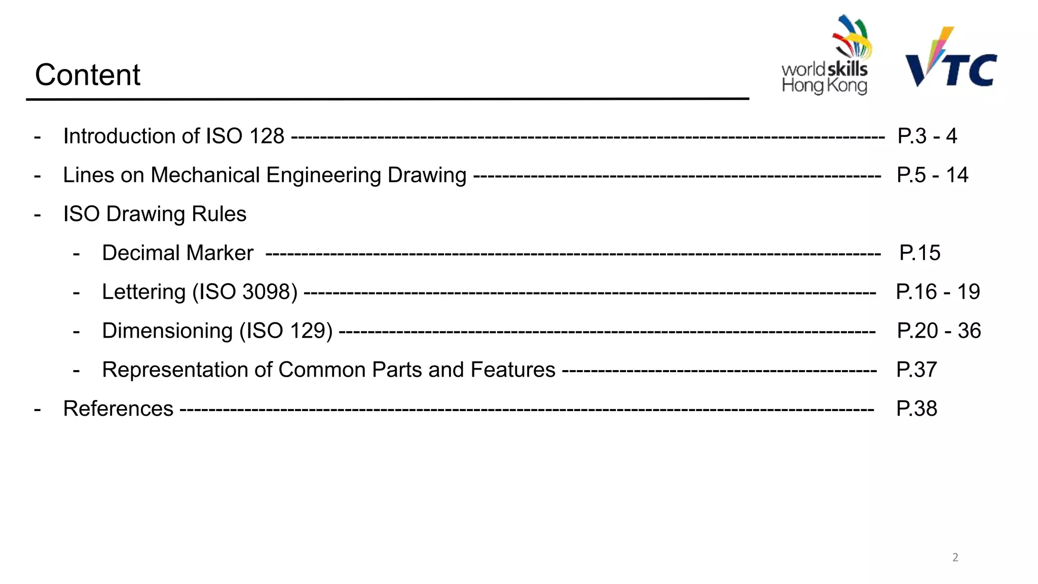
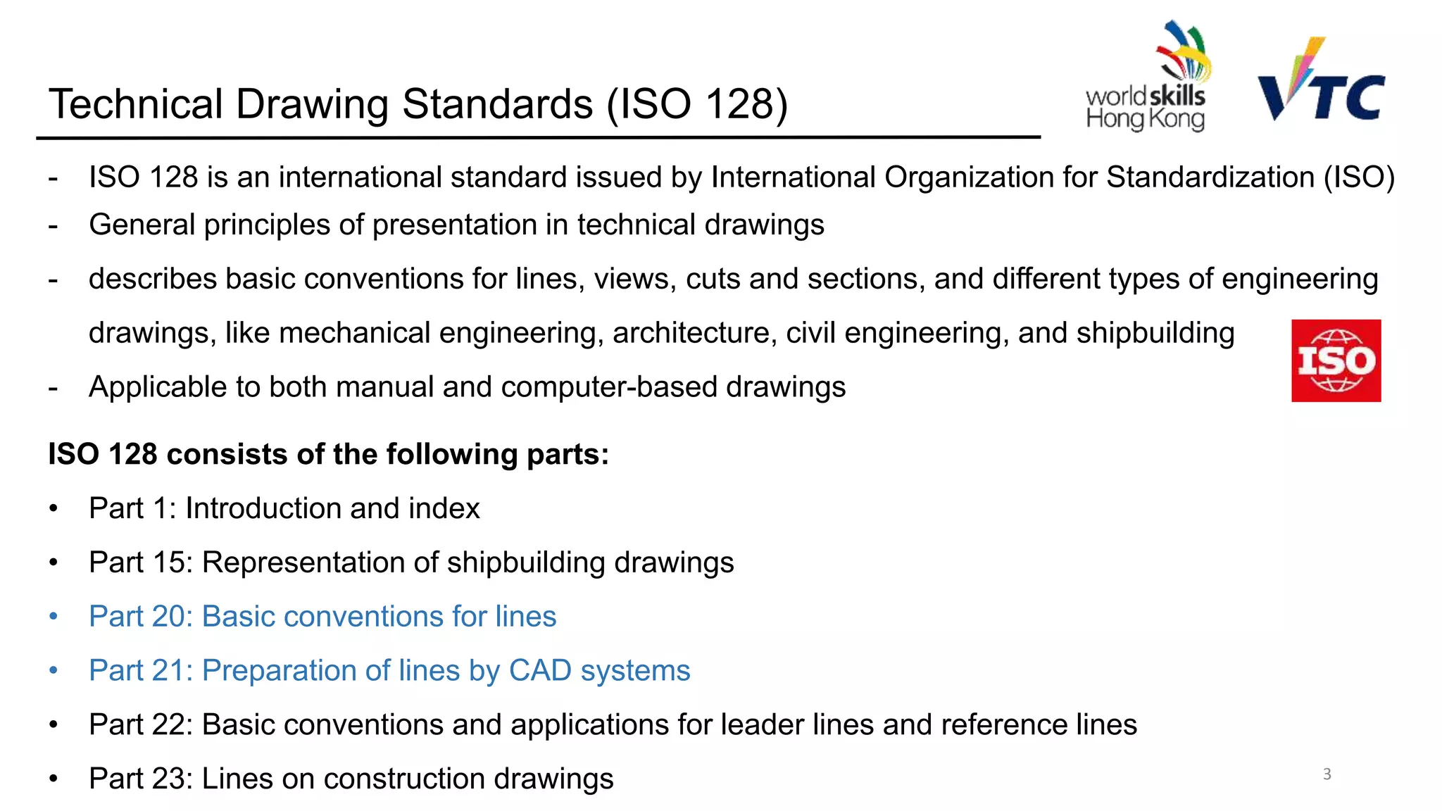
ISO 128 consists of the following parts:
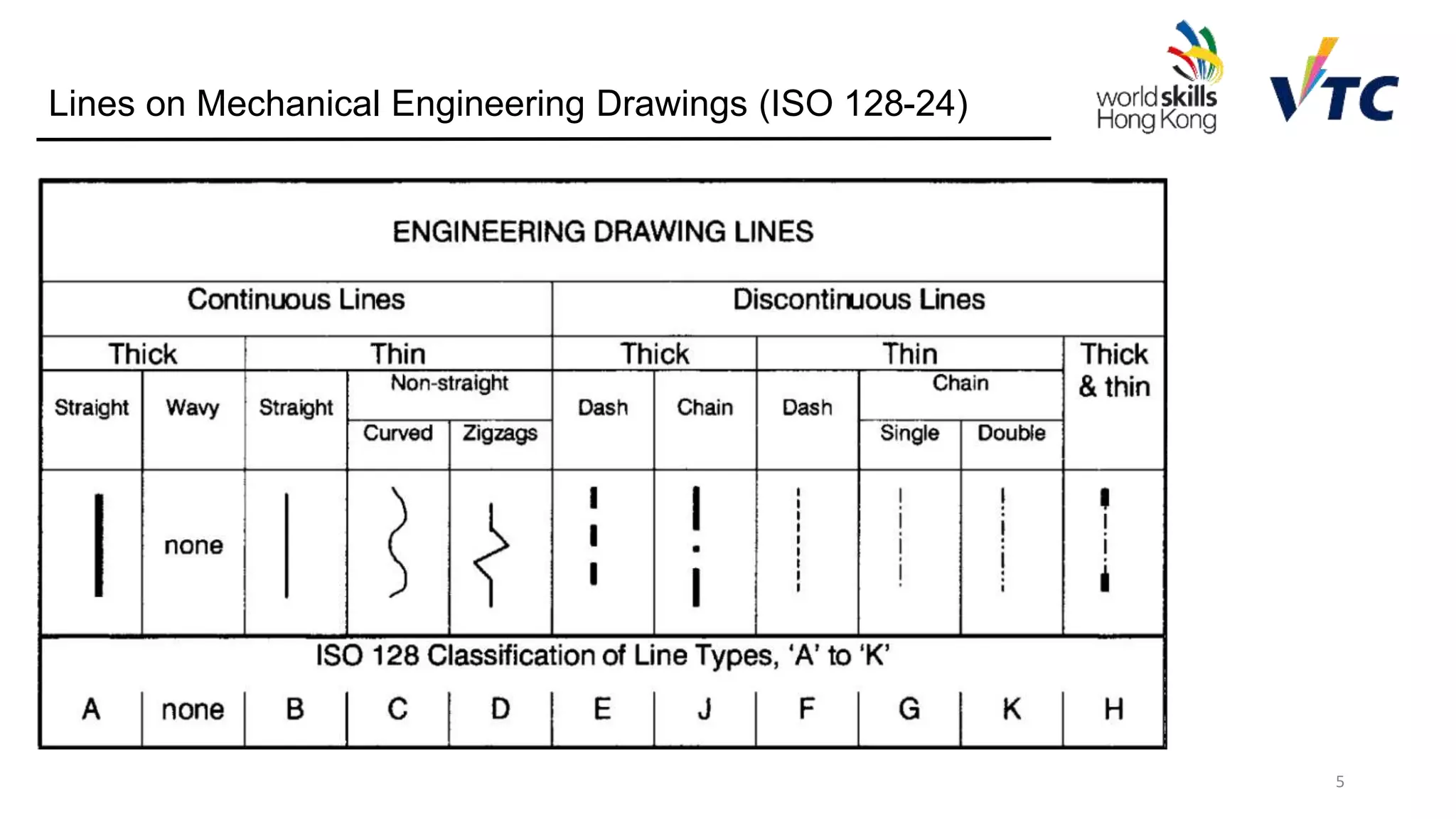
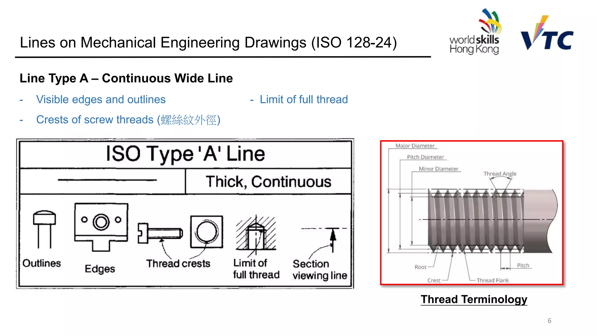
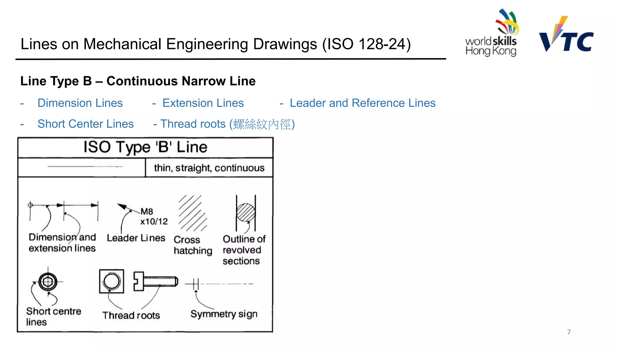
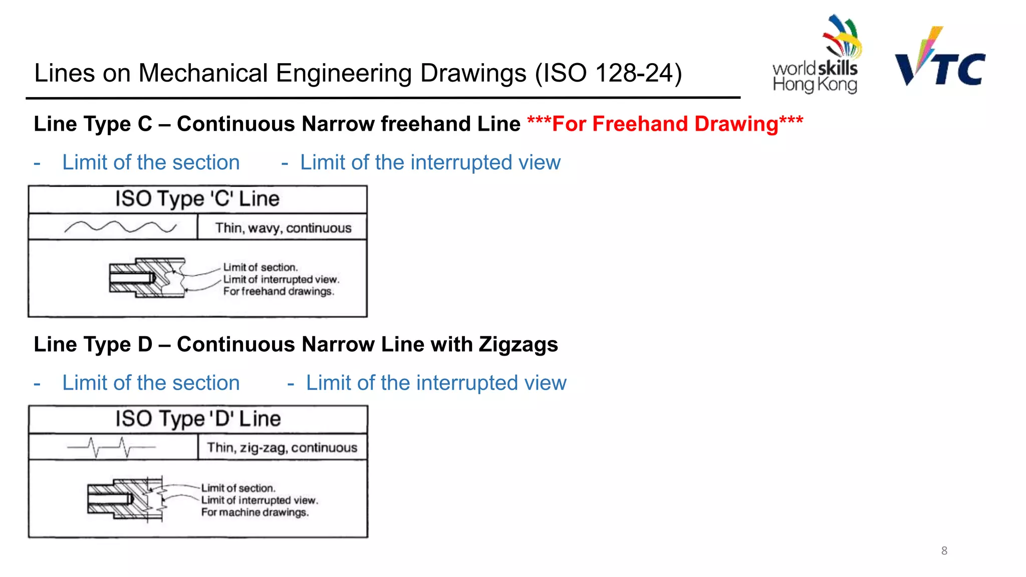
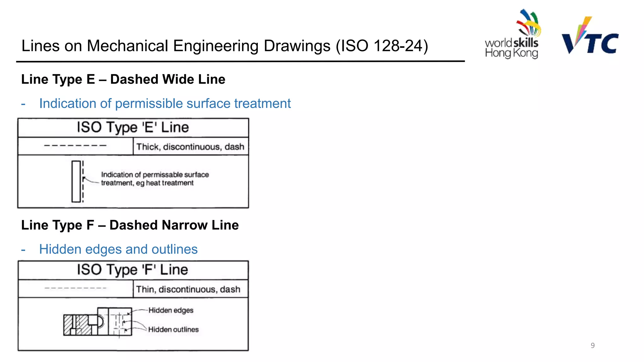
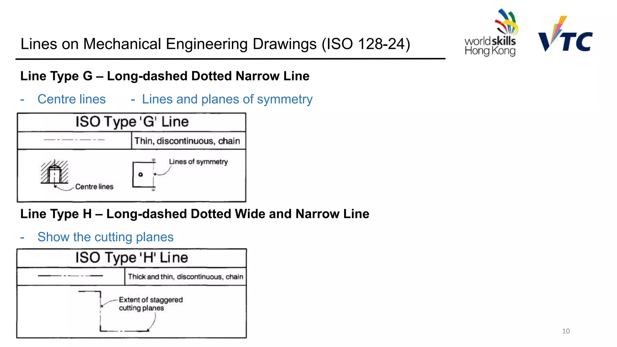
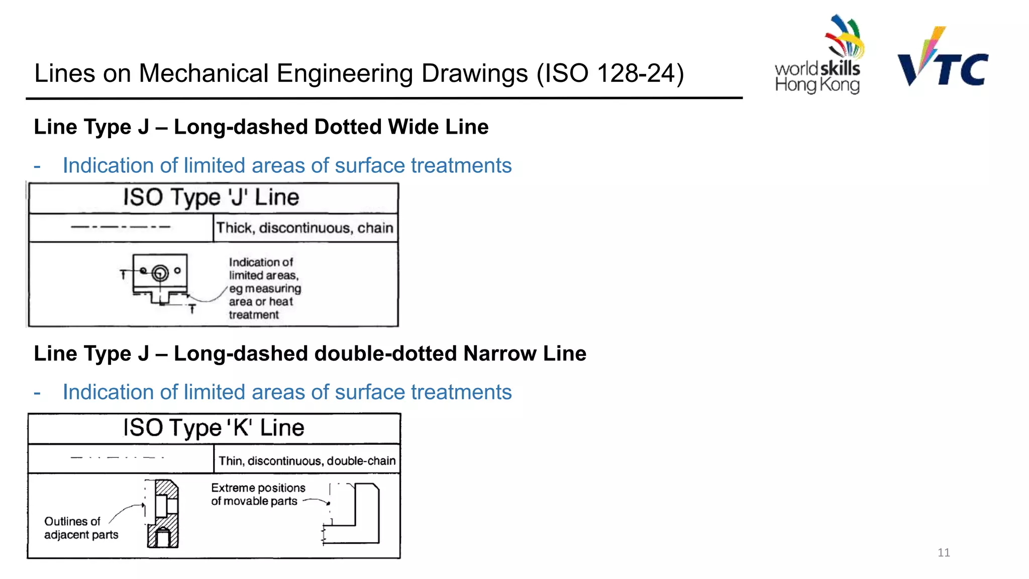
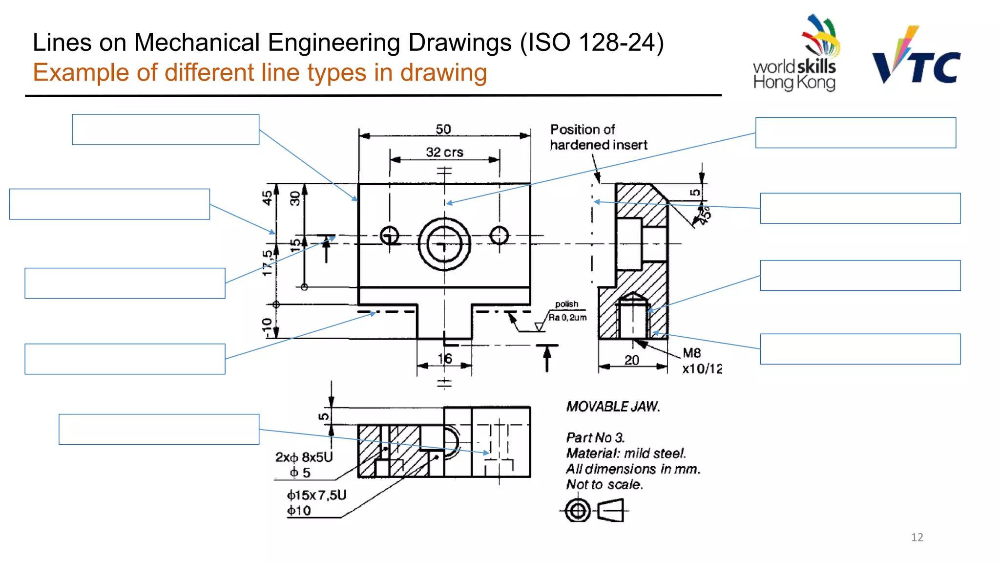
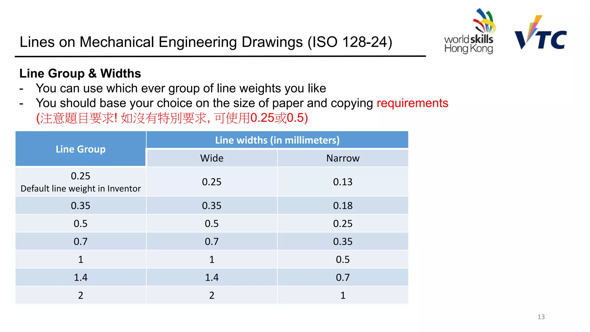
• Part 24: Lines on mechanical engineering drawings
• Part 25: Lines on shipbuilding drawings
• Part 30: Basic conventions for views
• Part 34: Views on mechanical engineering drawings
• Part 40: Basic conventions for cuts and sections
• Part 44: Sections on mechanical engineering drawings
• Part 50: Basic conventions for representing areas on cuts and sections
• Part 71: Simplified representation for mechanical engineering drawings [TS]
4
SI System:
- Millimeter (mm)
- Gram (g)
- Degree (°)](https://image.slidesharecdn.com/worldskillsmechanicalcadtechnicaldrawingstandard-190115080825/75/Introduction-of-ISO-standards-for-technical-engineering-drawing-4-2048.jpg)