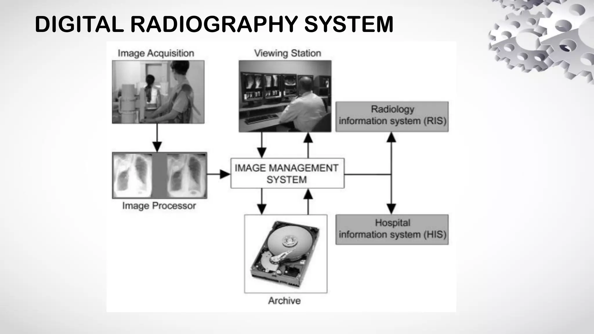
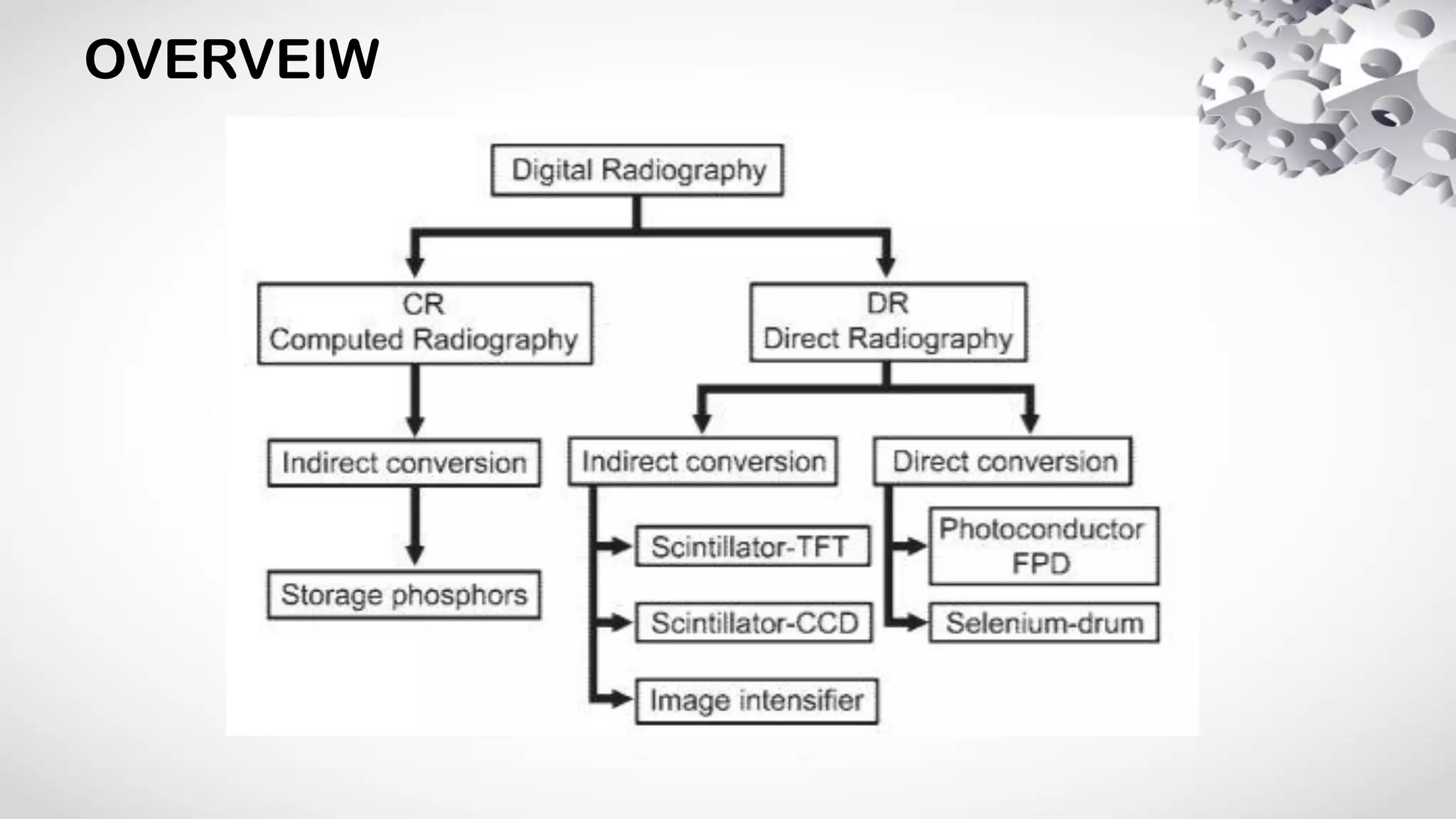
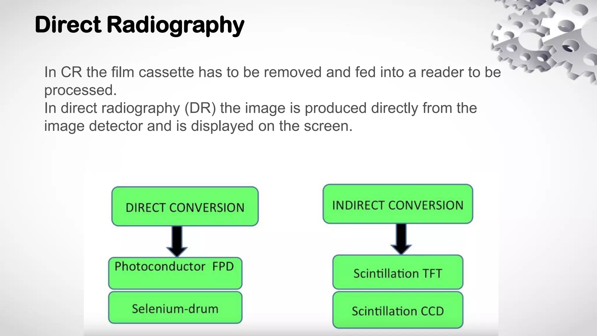
DIGITAL RADIOGRAPHY
Dr. Shubhankar
PGT Radiodiagnosis
HISTORY
YEAR DEVELOPMENT
1977 Digital subtraction angiography (Experimental)
1980 Computed radiography (CR), storage phosphors
1990 Charge-coupled device (CCD) slot-scan direct radiography (DR)
1994 Selenium drum direct radiography
1995 Amorphous silicon–cesium iodide (scintillator) flat-panel detector
1995 Selenium-based flat-panel detector
1997 Gadolinium-based (scintillator) flat-panel detector
2001 Gadolinium-based (scintillator) portable flat-panel detector
2001 Dynamic flat-panel detector fluoroscopy– digital subtraction angiography
DIGITAL RADIOGRAPHY SYSTEM
OVERVEIW
Computed Radiography (CR)
Components (CR)
Phosphor imaging plates (PIP)
• replaces the film
• captures the latent image
PIP Reader (Scanner)
• replaces the chemical processing steps
• reads the latent image
Workstation
• review, document, grade, and store the
final adjusted image
Image processing
LATENT IMAGE
FORMATION
LASER SIMULATED
EMISSION
RESETTING
CASSETTE
Image processing
Artefacts
Moiré pattern
• When a stationary x-ray anti-scatter grid is used there is interference between the linear
structure of the grid and the regular pixel array of the digitised image.
Artefacts
• Ghost image: due to carry-over of image content from a previous
exposure.
• Excessively high / low image density: due to faulty operation of
the data auto-ranging software.
• Excessive digital enhancement: e.g. ringing effects along the
edges of high density structures or shadowing within such
structures.
Advantages of CR
Disadvantages of CR
Direct Radiography
In CR the film cassette has to be removed and fed into a reader to be
processed.
In direct radiography (DR) the image is produced directly from the
image detector and is displayed on the screen.
Indirect Conversion
• Hardware
1) Scintillator layer
Most systems use a thin layer
of caesium iodide (CsI:TI) as a
scintillator to capture the image
and is coated onto the a-Si:H
active matrix array (some systems
use gadolinium oxysulfide as the
scintillator layer).
Hardware
2) Active matrix
This is formed by an amorphous silicon layer doped with hydrogen (a-Si:H) and forms the
readout electronics. Each pixel typically comprises:
• Photodiode (a light sensor) - amplifies signal from incident light photons
• Charge storage capacitor - stores signal of latent image
• Thin-film transistor (or TFT switch) - latent image read out and transferred to TFT switches
that produce a voltage signal that is digitised and converted into the image
3) TFT array
This is a device that amplifies the signal then stores it as an electrical charge. The charge can
be released and read by applying a high potential. In the array each transistor corresponds to a
pixel.
Image processing
• CsI:TI absorbs x-ray photons and releases light photons
• These light photons are then absorbed in the photodiodes
and the charge stored in the charge storage capacitor at
each pixel location
• The latent image is read out sequentially to a bank of
charge sensitive amplifier (TFT switches)
• The resulting voltage signal is then digitised and
transferred to the system computer where the DR image
is built up
Image processing
Charge-coupled device (CCD)
• CCD is a light-sensitive integrated
circuit that stores and displays the
data for an image in such a way
that each pixel (picture element)
in the image is converted into an
electrical charge the intensity of
which is related to a color in the
color spectrum.
Flat panel detector (FPD)
• FPD converts X-rays to light (indirect
conversion) or charge (direct conversion)
which is read out using thin film
transistors (TFT array).
Direct Conversion
• A layer of x-ray photoconductor material is used
instead of an x-ray scintillator.
Photoconductor
• Photoconductor directly converts x-ray photon energy into free electrical charge
carriers i.e. the "middle-men" or light photons, are cut out.
• The most commonly used photoconductor is amorphous selenium (a-Se).
Image processing
Amorphous selenium– based direct conversion DR systems.
Artefacts and correction
Artefacts
• Irregular shading across field: due to non-uniform variations in the sensitivity or gain of the
x-ray absorption layer
• Bright / dark spots or lines in image: due to individual rows and/or columns of defective
pixels in the active matrix array
Correction
• Gain calibration: uses previously acquired mask image comprising an image acquired with
a uniform x-ray beam and subtracting this gain mask image from the patient's image
• Pixel-calibration: defects in pixel array can be corrected by interpolating the data values of
neighbouring pixels which are functioning correctly using a reference map
Computed Radiography (CR) Direct Radiography (DR)
Lower initial investment Higher initial investment
Can be retrofitted to existing installations All-new setup necessary
Lower image quality Better image quality
More time to final image viewing (5-7 minutes) Rapid image viewing (within 1 minute)
Labor-intensive due to the need for cassette transfer
to the plate reader
Completely digitized setup
Lower patient throughput High patient throughput
More bulky Compact profile
Higher risk of overexposure Lower risk of overexposure
Suitable for low or moderate workflow Ideal for high workflow
Less efficient More efficient
Less costly to replace More costly parts, requires to be protected from
dropping or rough handling
QUIZ
Photostimulable phosphor (PSP)
Q. Used in CR or DR?
Q. Made up of?
QUIZ
Q. Name the ARTEFACT?
QUIZ
Q. Direct or Indirect
Conversion?
Thank You

Digital Radiography PHYSICS

  • 1.
  • 2.
    HISTORY YEAR DEVELOPMENT 1977 Digitalsubtraction angiography (Experimental) 1980 Computed radiography (CR), storage phosphors 1990 Charge-coupled device (CCD) slot-scan direct radiography (DR) 1994 Selenium drum direct radiography 1995 Amorphous silicon–cesium iodide (scintillator) flat-panel detector 1995 Selenium-based flat-panel detector 1997 Gadolinium-based (scintillator) flat-panel detector 2001 Gadolinium-based (scintillator) portable flat-panel detector 2001 Dynamic flat-panel detector fluoroscopy– digital subtraction angiography
  • 3.
  • 4.
  • 5.
  • 6.
    Components (CR) Phosphor imagingplates (PIP) • replaces the film • captures the latent image PIP Reader (Scanner) • replaces the chemical processing steps • reads the latent image Workstation • review, document, grade, and store the final adjusted image
  • 7.
    Image processing LATENT IMAGE FORMATION LASERSIMULATED EMISSION RESETTING CASSETTE
  • 8.
  • 9.
    Artefacts Moiré pattern • Whena stationary x-ray anti-scatter grid is used there is interference between the linear structure of the grid and the regular pixel array of the digitised image.
  • 10.
    Artefacts • Ghost image:due to carry-over of image content from a previous exposure. • Excessively high / low image density: due to faulty operation of the data auto-ranging software. • Excessive digital enhancement: e.g. ringing effects along the edges of high density structures or shadowing within such structures.
  • 11.
  • 12.
  • 13.
    Direct Radiography In CRthe film cassette has to be removed and fed into a reader to be processed. In direct radiography (DR) the image is produced directly from the image detector and is displayed on the screen.
  • 14.
    Indirect Conversion • Hardware 1)Scintillator layer Most systems use a thin layer of caesium iodide (CsI:TI) as a scintillator to capture the image and is coated onto the a-Si:H active matrix array (some systems use gadolinium oxysulfide as the scintillator layer).
  • 15.
    Hardware 2) Active matrix Thisis formed by an amorphous silicon layer doped with hydrogen (a-Si:H) and forms the readout electronics. Each pixel typically comprises: • Photodiode (a light sensor) - amplifies signal from incident light photons • Charge storage capacitor - stores signal of latent image • Thin-film transistor (or TFT switch) - latent image read out and transferred to TFT switches that produce a voltage signal that is digitised and converted into the image 3) TFT array This is a device that amplifies the signal then stores it as an electrical charge. The charge can be released and read by applying a high potential. In the array each transistor corresponds to a pixel.
  • 16.
    Image processing • CsI:TIabsorbs x-ray photons and releases light photons • These light photons are then absorbed in the photodiodes and the charge stored in the charge storage capacitor at each pixel location • The latent image is read out sequentially to a bank of charge sensitive amplifier (TFT switches) • The resulting voltage signal is then digitised and transferred to the system computer where the DR image is built up
  • 17.
  • 18.
    Charge-coupled device (CCD) •CCD is a light-sensitive integrated circuit that stores and displays the data for an image in such a way that each pixel (picture element) in the image is converted into an electrical charge the intensity of which is related to a color in the color spectrum.
  • 19.
    Flat panel detector(FPD) • FPD converts X-rays to light (indirect conversion) or charge (direct conversion) which is read out using thin film transistors (TFT array).
  • 20.
    Direct Conversion • Alayer of x-ray photoconductor material is used instead of an x-ray scintillator. Photoconductor • Photoconductor directly converts x-ray photon energy into free electrical charge carriers i.e. the "middle-men" or light photons, are cut out. • The most commonly used photoconductor is amorphous selenium (a-Se).
  • 21.
  • 22.
    Amorphous selenium– baseddirect conversion DR systems.
  • 23.
    Artefacts and correction Artefacts •Irregular shading across field: due to non-uniform variations in the sensitivity or gain of the x-ray absorption layer • Bright / dark spots or lines in image: due to individual rows and/or columns of defective pixels in the active matrix array Correction • Gain calibration: uses previously acquired mask image comprising an image acquired with a uniform x-ray beam and subtracting this gain mask image from the patient's image • Pixel-calibration: defects in pixel array can be corrected by interpolating the data values of neighbouring pixels which are functioning correctly using a reference map
  • 24.
    Computed Radiography (CR)Direct Radiography (DR) Lower initial investment Higher initial investment Can be retrofitted to existing installations All-new setup necessary Lower image quality Better image quality More time to final image viewing (5-7 minutes) Rapid image viewing (within 1 minute) Labor-intensive due to the need for cassette transfer to the plate reader Completely digitized setup Lower patient throughput High patient throughput More bulky Compact profile Higher risk of overexposure Lower risk of overexposure Suitable for low or moderate workflow Ideal for high workflow Less efficient More efficient Less costly to replace More costly parts, requires to be protected from dropping or rough handling
  • 25.
    QUIZ Photostimulable phosphor (PSP) Q.Used in CR or DR? Q. Made up of?
  • 26.
  • 27.
    QUIZ Q. Direct orIndirect Conversion?
  • 28.