The document provides information about differentials and how they work:
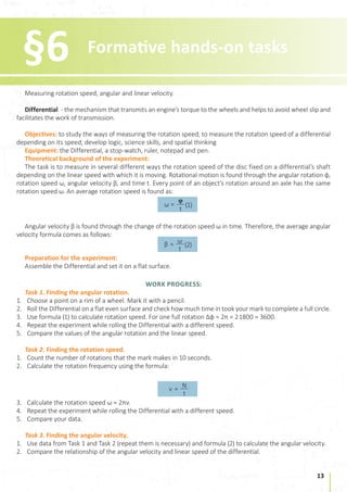
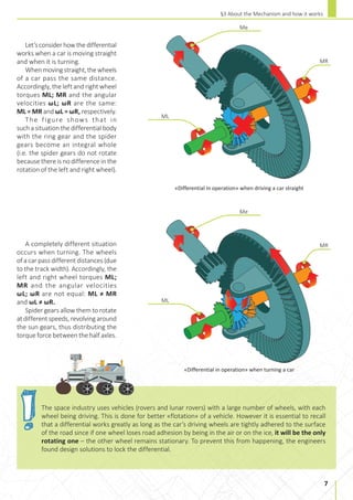
1) A differential is a gear arrangement that allows the left and right wheels of a vehicle to rotate at different speeds while turning, which improves stability and prevents slipping. It transmits torque from the engine and divides it between the two wheels.
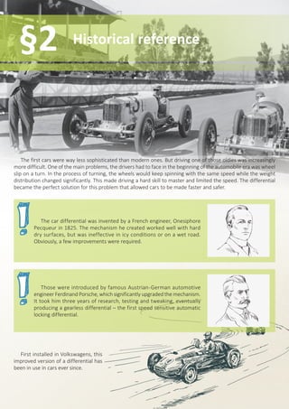
2) The first differential was invented in 1825 by a French engineer to address the problem of wheel slip when turning, but it was improved by Ferdinand Porsche in the early 20th century.
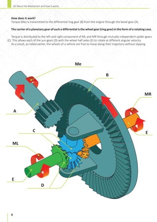
3) A differential uses planetary gears to distribute torque from the engine to the left and right half-axles. This allows the wheels to rotate at different speeds when turning or driving on uneven surfaces
The differential allows the two drive wheels of a vehicle to rotate at different speeds while turning a corner. It consists of an input drive shaft connected to a carrier that supports planetary gears connecting to the two driven axles. This allows the wheels to turn at different rates to maintain traction as one must travel a longer distance than the other when cornering.
This document summarizes a student project to design and analyze a differential gear box. It includes sections that describe the objective of analyzing the working of a vehicle differential and designing the system. It explains the key parts of a differential system including the pinion gear, ring gear, spider gear, and differential case. It also describes the working of a differential for straight driving and turning, and discusses issues like one wheel slipping. Design parameters and the forces that allow the spider gear to rotate are analyzed. Finally, it briefly mentions the types of differentials.
An automobile differential couples the drive shaft to the rear driving wheels. It allows the outer wheel to rotate faster than the inner wheel during a turn by splitting torque equally between the wheels. A differential consists of one input and two outputs for the two driving wheels. It allows the wheels to rotate at different speeds to accommodate turns while keeping the average rotational input equal to the drive shaft. Differentials are commonly used in automobiles but also have non-automotive applications like performing analog arithmetic or controlling gun aim. There are different types of differentials like epicyclic, spur gear, and bevel gear differentials.
The document describes an automobile differential and how it works. It discusses:
1) The purpose of a differential is to allow the two driving wheels to rotate at different speeds while receiving equal torque, which is necessary when turning corners.
2) Key components of a differential include the pinion gear, ring gear, spider gears, side gears, and differential case. Spider gears connect to side gears and allow them to rotate independently.
3) During a turn, the spider gear rotates to drive the outside wheel faster than the inside wheel, matching their different path lengths and allowing the vehicle to turn smoothly.
The document discusses differentials and solid axles. It provides information on different types of differentials including their purpose, history, functional description, and traction-aiding devices. It also discusses live (solid) axles, describing their advantages as simplicity and lower cost, and disadvantages as reduced ride quality and handling due to the wheels not moving independently. Live axles remain common on trucks and other heavy vehicles due to their robustness.
This technical seminar presentation summarizes the key components and functions of an automobile differential system. It discusses:
1) The main parts of a differential system including the pinion gear, ring gear, spider gears, differential case assembly, and rear drive axles.
2) How differentials work by allowing the outer wheels to travel farther than the inner wheels when turning, while maintaining equal torque to both wheels.
3) The drawback of a standard open differential which can send all torque to a single slipping wheel, and how limited-slip differentials address this issue.
This document discusses different types of differentials used in vehicles. It begins with an introduction describing how the differential was first used in 1897 and evolved over time. Then it describes the key components and functioning of a basic differential, allowing the left and right wheels to rotate at different speeds during turns. The document goes on to explain different types of differentials including open differentials, limited slip differentials, and Torsen differentials. It concludes by discussing differential locks and their applications in vehicles like race cars and off-road vehicles.
The document provides an answer key for a mechanical engineering exam on automobile engineering. It includes multiple choice questions on topics like axle failures, universal joints, overdrive systems, and steering principles. It also includes longer answer questions on components like clutches, gearboxes, differentials, and rear axle designs. The last section defines important steering geometry terms that describe the angular relationship between suspension parts and how it affects vehicle handling.
Automobile differential unit explained with the types and general maintenance. Procedure involved in dis-assembly of differential unit is also explained. Then solutions for common problem in differential unit.
This document provides information about synchromesh gearboxes. It discusses how synchromesh gearboxes allow for smooth shifting between gears without needing to double clutch. Synchromesh gearboxes contain synchronizer rings that allow the gears to synchronize speed before engaging through friction. This synchronization avoids clashing when shifting gears. The document outlines the construction and working of synchromesh gearboxes, including how the synchronizer rings slide to equalize gear speeds before engagement. It discusses advantages like smooth shifting and disadvantages like higher cost compared to other gearbox types. Applications and recent literature on synchromesh gearbox design improvements are also summarized.
The document discusses different components of an automotive transmission system including the gear box. It describes the purpose of a gear box as providing speed and torque conversions to maintain the engine's optimal operating speed under varying driving conditions. Several types of gear boxes are summarized, including sliding mesh, constant mesh, synchro-mesh, and planetary/epicyclic gear boxes. Key components like synchronizers and the gear shifting mechanism are also explained at a high level. The document concludes by discussing other transmission components like the torque converter and overdrive system.
The document discusses the history and development of automobiles. It begins by defining an automobile as a self-propelled vehicle used to transport people and goods over land. It then traces the origins of automobiles back to 15th century inventions, with Captain Nicholas Cugnot considered the father of the modern automobile. The first motor car arrived in India in 1898. The document goes on to discuss various automobile manufacturers in India and classifications of vehicles based on purpose, fuel used, capacity, wheels, and transmission.
This document provides an overview of automotive transmission systems. It discusses various components of the transmission system including the clutch, gearbox, propeller shaft, differential, and rear axle. It describes the purpose of each component and their functions. For the clutch, it covers different types such as single plate, multi-plate, cone, and hydraulic clutches. It also discusses gearboxes, focusing on manual transmissions like sliding mesh, constant mesh, and synchromesh gearboxes. The document aims to explain the purpose and working of the main components that transmit power from the engine to the drive wheels.
The document discusses various axle systems used in vehicles. It describes the construction and function of rear axles, front axles, and stub axles. Rear axles are mounted at the rear of the vehicle and use axle shafts to transmit power from the differential to the rear wheels. Front axles provide steering action and support the front of the vehicle. Stub axles connect the wheels to the front and rear axles. The document outlines different types of rear axles including semi-floating, full-floating, and three-quarter floating designs.
- The drive pinion drives the ring gear which is attached to the differential case. When going straight ahead, power is transferred equally to both wheels. When turning a corner, the wheels must travel at different speeds to prevent tire scrubbing, so the differential pinion gears "walk" around the slower side gear to cause the other side gear to turn faster.
- Limited-slip differentials limit the amount of differential action allowed compared to open differentials. They provide more driving force to the wheel with traction when one wheel begins to slip while still allowing wheels to turn at different speeds when cornering.
- In operation, driving torque is transmitted equally to each axle until traction is lost by one wheel. Then
1. A differential is a gear train that allows the outer drive wheel of a vehicle to rotate faster than the inner drive wheel during a turn, which is necessary for the vehicle to turn.
2. The differential couples the input shaft to two output shafts for the two drive wheels. It has the property that the average rotational speed of the two driving wheels equals the input speed, while allowing one wheel to rotate faster than the other.
3. The earliest known use of a differential was in the ancient Antikythera mechanism from Greece in around 80 BC, which used it to model the moon's phases. Differentials are now universally used in automobiles and other wheeled vehicles to allow the wheels to rotate
anna university automobile engineering unit 1 suresh n
automobile engineering, frames, vehicle body,two stroke and four engine difference, valve timing and port timing diagram, engine classification,engine layout, ic engine components,
The document discusses different types of differentials used in automobiles. It begins by introducing the basic components and purpose of a differential, which allows the left and right wheels to spin at different speeds during turns. It then describes the key parts of a differential system and how power is transferred. The document explains how an open differential can limit traction in certain conditions, and introduces limited-slip and active differentials as alternatives that can distribute torque more effectively. It concludes by noting some other differential types like locking and automatic torque biasing differentials.
The document provides information about different types of clutches used in transmission systems. It discusses the functions of transmission systems and defines what a clutch is. It then describes various types of clutches in detail, including positive clutches, friction clutches, single plate clutches, multi plate clutches, diaphragm clutches, centrifugal clutches, and free wheel clutches. It also discusses the requirements, location, and actuating mechanisms of clutches.
1. The transmission system connects the engine to the wheels through components like the clutch, transmission, transfer case, propeller shaft, differential, and gears.
2. The transmission allows drivers to select between different gear ratios to optimize engine speed and torque based on the vehicle's speed and acceleration needs.
3. Key components include the clutch which connects and disconnects the engine from the transmission, while the transfer case distributes power from the transmission to the front and rear axles for 4-wheel drive vehicles.
The document discusses different types of gearboxes used in vehicles including sliding mesh, constant mesh, and synchromesh gearboxes. It explains their basic workings, advantages, and disadvantages. The document also covers topics like vehicle resistance, torque converter, and epicyclic gear sets used in automatic transmissions.
This document provides information on various components of automobile transmissions and gearboxes. It discusses the functions of gearboxes including varying torque ratios for acceleration and climbing gradients. It describes different types of transmissions including sliding mesh gearboxes, constant mesh gearboxes, and gearboxes with synchromesh or dog clutches. Continuously variable transmissions, torque converters, propeller shafts, differentials, axles, and the hotchkiss drive system are also outlined. Electronic transmission controls, overdrive systems, freewheels, universal joints, and power flow through the drivetrain are summarized as well.
differential gear mechanism BY ANUBHAV SINGHAnubhav659
The document discusses the differential gear mechanism used in vehicles, including its key parts like the pinion drive gear, ring gear, and differential case assembly. It describes how the differential allows the outer wheels to rotate faster than the inner wheels during turns using planetary gearing. Maintenance and troubleshooting of differentials is also covered, such as checking for bearing or gear issues and adjusting ring and pinion backlash.
Gearboxes in automobiles provide speed and torque conversions from the engine to allow for different gear ratios. They reduce the load on the engine and allow greater control and speeds. Early transmissions included gearing in windmills and steam engines. Modern gearboxes mostly decrease shaft speed while increasing torque, but can also increase speed with reduced torque. Automatic transmissions use planetary gear sets instead of manually selecting gears. Various types of gearboxes include manual, semi-automatic, automatic, dual-clutch, CVT, and electric transmissions.
The document discusses various components and types of steering systems used in vehicles. It describes the basic components that make up a steering system including the steering wheel, steering column, steering gears, linkages and wheels. It then explains different types of steering gears including worm and wheel, worm and sector, cam and lever, recirculating ball, and rack and pinion systems. The document also covers power steering systems that use hydraulic or electric motors to assist the driver by reducing steering effort.
The document provides an overview of automobile transmission systems and differentials. It discusses how differentials allow the left and right drive wheels to turn at different rates when negotiating turns. The differential divides torque equally between the wheels using a set of gears that allow the wheels to rotate at different speeds. This prevents issues like one wheel spinning or dragging that could occur without a differential. It then describes the basic components and functioning of a typical automobile differential gear train.
Power transmission involves moving energy from where it is generated to where it is applied. The first link is the flywheel, which stores rotational energy and resists changes in speed. Problems with flywheels include high mass and rotational inertia. Solutions include using minimum diameter flywheels and materials like aluminum that have low mass and maximum strength. Differentials distribute engine torque to both wheels but allow them to spin at different speeds, while locking differentials restrict both wheels to the same speed regardless of traction.
The document discusses why clutches are needed in vehicles and how they work. Clutches allow the engine and transmission to be engaged and disengaged, which is necessary when starting from a stop and changing gears. They connect the two rotating shafts of the engine and transmission to either lock them together and spin at the same speed or decouple them to spin at different speeds. The clutch contains plates that can be engaged to smoothly transfer power from the engine to the transmission.
The document discusses differentials and their components. A differential is located in the rear axle assembly and splits torque from the drive shaft to allow the left and right wheels to spin at different speeds when turning. It discusses the types of gears used including spiral bevel gears and hypoid gears. It also describes the different types of differentials including open differentials, limited slip differentials, and locking differentials. The advantages and disadvantages of each type are provided. Measurements and adjustments that are important for differentials like pinion gear depth, pinion bearing preload, and ring and pinion backlash are also outlined.
This seminar report discusses dual clutch transmission systems. It begins with an introduction to transmission systems in general and their components. It then discusses different types of transmission systems like manual, automatic, and torque converter systems. The bulk of the report focuses on dual clutch transmission systems, including their history, overview, components like the clutches used, and comparisons to automatic and manual systems. It provides details on how dual clutch transmissions work and the benefits they provide over traditional automatic transmissions.
The document discusses the operation of different types of vehicle transmissions, including automatic and manual transmissions. It describes the main components of transmissions like the torque converter, gear sets, clutches, and shafts. The relationships between gear ratios, angular velocity, and shaft work are analyzed from a thermodynamic perspective. Both automatic and manual transmissions are compared in terms of their components and how power is transferred from the engine to the wheels.
This document appears to be an industrial training report submitted by a student named Koushik Bibra after completing an internship at H.R.T.C. Dharamshala. The report includes an acknowledgements section, abstract, and sections covering the main parts of an automobile including the chassis, engine, transmission system, propeller shaft, differential, brakes, suspension system, and steering system. Diagrams and descriptions of these systems are provided.
The document provides an introduction to automobile engineering. It defines automobile engineering and vehicles, classifying vehicles based on load, wheels, fuel used, body, and transmission. It describes the key components of an automobile, including the engine, frame and chassis, transmission system, braking system, steering system, front axle, and suspension system. It provides a diagram of a typical automobile chassis layout and explains the basic functions of the major automobile components.
automobile workshop ppt Traning report by c rang rajan and sudhir kumarchakrawarti rang rajan
The document provides an overview of the key components and systems of an automobile. It begins with an introduction to Karlo Automobiles, an Indian vehicle repair workshop. It then defines an automobile and describes its main parts like the engine, transmission system including the clutch, gearbox, propeller shaft, differential, wheels, axle and chassis. The document further explains the body, suspension system, cooling system, steering system, braking system and lighting system of a car. Diagrams and pictures are included to illustrate the different components. The presentation aims to provide trainees an understanding of the various parts that make up a motor vehicle.
Differential and Rear Axle Drives, by Jeevan B MJeevan B M
A differential is a device capable of transmitting torque and rotation through three shafts, almost always used in one of two ways.
Rear axle drives are the drives which employed for the rear axle the spring take the weight of the body.
The transmission system transmits power from an automobile's engine to the rear driving wheels. It includes components like the clutch, gearbox, propeller shaft, differential, and rear axle. The clutch connects and disconnects the engine from the rest of the drivetrain. The gearbox uses different gear ratios to change the speed and torque delivered to the propeller shaft. The propeller shaft then transmits power to the differential, which uses planet gears to allow the rear wheels to rotate at different speeds while driving. The transmission system allows the vehicle to be driven at varying speeds and torque levels.
Gearbox is a device that changes the speed and torque between an engine and driving wheels. It has several purposes, including allowing the engine to disconnect from driving wheels, connecting the engine and wheels smoothly without shock, and providing leverage to vary the relationship between engine and wheel speeds. There are several types of gearboxes, including manual transmissions, automatic transmissions, and epicyclical gearboxes. A sliding mesh gearbox is the simplest type - it uses spur gears and has gears on a main shaft that can slide to engage with gears on a lay shaft, changing gears. In neutral, with the engine running and clutch engaged, gears on the transmission shaft do not rotate and no motion is transmitted to the output shaft,
This document describes a project to implement a four-wheel steering system with three steering modes in a single vehicle. The system allows the vehicle to steer the front wheels normally, steer both the front and rear wheels in the same direction for improved stability at higher speeds, and steer the front and rear wheels in opposite directions to achieve a tighter turning radius at low speeds such as during parking maneuvers. The system uses gears and linkages to synchronize the steering of the front and rear wheels and allow switching between the three steering modes.
This document provides an overview of different types of transmissions. It begins by defining a transmission as a machine that provides controlled application of power through gear ratios and torque conversions. It then discusses specific transmission types for motor vehicles including manual transmissions, which can be non-synchronous, synchronized, sequential, or have preselection of gears. Automatic transmissions are also covered, including types like manumatic and semi-automatic. Other transmission applications discussed include those for bicycles, with details on derailleur and hub gears, as well as those used in industrial machinery.
This document summarizes a technical seminar presentation on automobile differential systems. It includes:
- An introduction describing how differentials allow wheels to spin at different speeds during turns.
- Descriptions of the main parts of a differential system including the pinion gear, ring gear, spider gears, and drive axles.
- An explanation of how differentials work during straight driving and turns.
- Other differential functions like speed reduction and changing the power flow direction.
- The drawback of open differentials losing power during wheel slip and an overview of limited slip differentials.
The document discusses making effective presentations by engaging audiences and capturing their attention. It provides tips on using awesome backgrounds to enhance presentations. The main topics covered are automobile engineering, including the history and classifications of vehicles, important components like the clutch, gear, gearbox, differential, steering system, and braking system. It describes how these systems work at a high level.
A clutch is a mechanism that connects two rotating shafts and allows them to be engaged and disengaged. There are several types of clutches, including friction clutches, centrifugal clutches, dog clutches, and fluid couplings. Friction clutches are the most common type used in vehicles and use friction plates or discs to connect the engine and transmission. They can be wet (immersed in fluid) or dry. Centrifugal clutches use centrifugal force to engage as RPM increases. Dog clutches lock two components together without slippage. Fluid couplings transmit power hydrodynamically using hydraulic fluid.
A clutch is a mechanism that connects two rotating shafts and allows them to be engaged and disengaged. There are several types of clutches, including friction clutches, centrifugal clutches, dog clutches, and fluid couplings. Friction clutches are the most common type used in vehicles and use friction plates or discs to connect the engine and transmission. They can be wet or dry and are found in automobiles, motorcycles, and other machinery. Centrifugal clutches use centrifugal force to engage and disengage, while dog clutches connect shafts through interference instead of friction. Fluid couplings transmit power hydrodynamically using hydraulic fluid.
This document summarizes various components that transmit power from an engine to the drive wheels of a vehicle, including the clutch, transmission, transaxle, drive shaft, differential, and torque tube system. The torque tube system, also known as a Hotchkiss drive, uses two universal joints to transmit power from the transmission to the rear axle while allowing for suspension movement and canceling out speed fluctuations in the driveshaft. This system was commonly used in rear-wheel drive vehicles from the 1920s through the 1970s.
Similar to Differential pocket-study-guide-ugears-stem-lab-de (20)
Welcome to ASP Cranes, your trusted partner for crane solutions in Raipur, Chhattisgarh! With years of experience and a commitment to excellence, we offer a comprehensive range of crane services tailored to meet your lifting and material handling needs.
At ASP Cranes, we understand the importance of reliable and efficient crane operations in various industries, from construction and manufacturing to logistics and infrastructure development. That's why we strive to deliver top-notch solutions that enhance productivity, safety, and cost-effectiveness for our clients.
Our services include:
Crane Rental: Whether you need a crawler crane for heavy lifting or a hydraulic crane for versatile operations, we have a diverse fleet of well-maintained cranes available for rent. Our rental options are flexible and can be customized to suit your project requirements.
Crane Sales: Looking to invest in a crane for your business? We offer a wide selection of new and used cranes from leading manufacturers, ensuring you find the perfect equipment to match your needs and budget.
Crane Maintenance and Repair: To ensure optimal performance and safety, regular maintenance and timely repairs are essential for cranes. Our team of skilled technicians provides comprehensive maintenance and repair services to keep your equipment running smoothly and minimize downtime.
Crane Operator Training: Proper training is crucial for safe and efficient crane operation. We offer specialized training programs conducted by certified instructors to equip operators with the skills and knowledge they need to handle cranes effectively.
Custom Solutions: We understand that every project is unique, which is why we offer custom crane solutions tailored to your specific requirements. Whether you need modifications, attachments, or specialized equipment, we can design and implement solutions that meet your needs.
At ASP Cranes, customer satisfaction is our top priority. We are dedicated to delivering reliable, cost-effective, and innovative crane solutions that exceed expectations. Contact us today to learn more about our services and how we can support your project in Raipur, Chhattisgarh, and beyond. Let ASP Cranes be your trusted partner for all your crane needs!
Fleet management these days is next to impossible without connected vehicle solutions. Why? Well, fleet trackers and accompanying connected vehicle management solutions tend to offer quite a few hard-to-ignore benefits to fleet managers and businesses alike. Let’s check them out!
Implementing ELDs or Electronic Logging Devices is slowly but surely becoming the norm in fleet management. Why? Well, integrating ELDs and associated connected vehicle solutions like fleet tracking devices lets businesses and their in-house fleet managers reap several benefits. Check out the post below to learn more.
What Could Be Behind Your Mercedes Sprinter's Power Loss on Uphill RoadsSprinter Gurus
Unlock the secrets behind your Mercedes Sprinter's uphill power loss with our comprehensive presentation. From fuel filter blockages to turbocharger troubles, we uncover the culprits and empower you to reclaim your vehicle's peak performance. Conquer every ascent with confidence and ensure a thrilling journey every time.
2. 2
Introduction
§1
The modern car has many parts and details. Each of them is very important. Certainly, you wouldn’t go far
in a car with no engine, or wheels, or, for example, the accelerator pedal. Today we want to look at one of the
most essential mechanisms – the differential. The device which plays an important role in maintaining a car’s
stability and keeps it steady and fast on any track.
Differentials are mainly used in automobile transmission*.
Their main function is to make steering easier and improve
the manoeuvrability of a vehicle.
The differential transmits and divides the
engine power and the torque** into two flows
between the wheels on the same axle (as
well as the tracks or propellers used in
other vehicles). This allows wheels to
rotate at different speeds making the
vehicle more stable, without slipping,
reducing tyre wear if one of the
wheels has poor road adhesion. For
example, when turning or driving
on slippery surfaces.
Next, you will learn in detail
what the differential is used for,
who has created it and when, how
it works and how and where it is
used today.
“Differential” 3D-model will help you to understand in practice the operation of this mechanism. By assembling
it with your own hands, you will unravel all the secrets of this important device.
Transmission (lat. transmissio). In vehicles, these are mechanisms connecting engine and driving wheels.
Right half
axle torque
Left half
axle torque
Engine torque
Power flow
from engine
* In this case, “torque” is the rotational effect of the force on the elements and parts of a mechanism. In the international system (SI) the moment
of force (or in our case, the torque) is measured in Newton metre (N · m).
Power flow
distribution
from engine
3. Historical reference
§2
The first cars were way less sophisticated than modern ones. But driving one of those oldies was increasingly
more difficult. One of the main problems, the drivers had to face in the beginning of the automobile era was wheel
slip on a turn. In the process of turning, the wheels would keep spinning with the same speed while the weight
distribution changed significantly. This made driving a hard skill to master and limited the speed. The differential
became the perfect solution for this problem that allowed cars to be made faster and safer.
First installed in Volkswagens, this
improved version of a differential has
been in use in cars ever since.
The car differential was invented by a French engineer, Onesiphore
Pecqueur in 1825. The mechanism he created worked well with hard
dry surfaces, but was ineffective in icy conditions or on a wet road.
Obviously, a few improvements were required.
Those were introduced by famous Austrian-German automotive
engineer Ferdinand Porsche, which significantly upgraded the mechanism.
It took him three years of research, testing and tweaking, eventually
producing a gearless differential – the first speed sensitive automatic
locking differential.
4. 4
Differential (from Latin: Differentia – difference) is a gear arrangement with shafts.
Let’s look at the composition parts of the symmetrical bevel-gear differential.
1
8
9
7
3
2
4
5
4 6
About the Mechanism
and how it works
§3
1 — left half axle; 2 — spider gear assembly; 3 — axle side gear; 4 — spider gears; 5 — spider pins; 6 — axle side
gear; 7 — spider gear assembly (with ring gear); 8 — right half axle; 9 — axle driven gear;
5. 5
§3 About the Mechanism and how it works
A planetary gear is the basic
element of any differential. This
is a mechanical transmission of
rotational motion which due to
its design is capable of changing,
adding and distributing the input
angular velocities* and/or the
torque to the spider gears along
the same axis of rotation. It also
includes the ring gear, the carrier
and the central “sun” gear.
* Angular velocity is a vector quantity that characterizes the speed and direction of a solid body rotation (in our case, parts of the mechanism
and wheels) relative to the centre of rotation. It is denoted by the Greek letter ω (omega) and measured in radians per second (rad/s). Next, we
consider this and other quantities in more detail.
** Driving wheels are the wheels to which the torque generated by the engine is transmitted. Both the rear wheels and the front wheels can be
driving. In four-wheel drive vehicles, all four wheels are driving. You must have come across such a «4x4» icon. 4х4 .
Ring gear
Carrier
Therefore, in a car, the differential has three main functions: torque transfer from the engine to the
drive wheels; ensuring the wheels individual angular velocity; and together with the axle drive, serves
as gear reduction unit.
Sun gear
Spider gears
When turning or driving on a rough road driving wheels** travel different
distances, as shown in the figure (due to the track width of a car).
The radii of the trajectory when turning are different for the left and
right wheels (Rex
is the radius of the external trajectory; Rin
is the radius of
the internal trajectory).
Thus, if both wheels received the same force (torque) from the engine,
then their rotation speed would accordingly be the same. Under these
conditions, one of the wheels is bound to be slipping. However, if you
put a differential between the wheels, you‘ll be able to distribute the
force from the engine and get different wheel speeds. So, the wheels run
at a required speed independently of each other.
Rex
Rin
6. 6
§3 About the Mechanism and how it works
How does it work?
Torque (Me) is transmitted to the differential ring gear (B) from the engine through the bevel gear (A).
The carrier of a planetary gear of such a differential is the wheel gear (ring gear) in the form of a rotating case.
Torque is distributed to the left and right component of ML and MR through mutually independent spider gears
(С). This allows each of the sun gears (D) with the wheel half axles (E) to rotate at different angular velocity.
As a result, as noted earlier, the wheels of a vehicle are free to move along their trajectory without slipping.
Me
MR
B
E
E
A
D
ML
C
7. 7
§3 About the Mechanism and how it works
Let’sconsiderhowthedifferential
works when a car is moving straight
and when it is turning.
Whenmovingstraight,thewheels
of a car pass the same distance.
Accordingly, the left and right wheel
torques ML; MR and the angular
velocities ωL; ωR are the same:
ML = MR and ωL = ωR, respectively.
The figure shows that in
such a situation the differential body
with the ring gear and the spider
gears become an integral whole
(i.e. the spider gears do not rotate
because there is no difference in the
rotation of the left and right wheel).
Me
MR
ML
A completely different situation
occurs when turning. The wheels
of a car pass different distances (due
to the track width). Accordingly, the
left and right wheel torques ML;
MR and the angular velocities
ωL; ωR are not equal: ML ≠ MR
and ωL ≠ ωR.
Spider gears allow them to rotate
at different speeds, revolving around
the sun gears, thus distributing the
torque force between the half axles.
«Differential in operation» when driving a car straight
«Differential in operation» when turning a car
The space industry uses vehicles (rovers and lunar rovers) with a large number of wheels, with each
wheel being driving. This is done for better «flotation» of a vehicle. However it is essential to recall
that a differential works greatly as long as the car’s driving wheels are tightly adhered to the surface
of the road since if one wheel loses road adhesion by being in the air or on the ice, it will be the only
rotating one – the other wheel remains stationary. To prevent this from happening, the engineers
found design solutions to lock the differential.
Me
MR
ML
8. 8
§3 About the Mechanism and how it works
So, there are several types of differentials:
Adifferentialwithmanuallocking–positivelockingisrequiredtoimproveoff-roadperformance.
It can be activated by a driver as needed.
Self-locking:
Visco drive is a multi-plate coupling in which the torque grows as the speed difference increases between the
drive and driven shafts. It is used in full-time all-wheel drive cars and as a differential locking mechanism;
This type of assemblies significantly increase vehicle flotation. The basic principle of self-locking is that certain
driving conditions are conducive to the automatic locking of a differential. When there is a significant increase in
load difference in the half axles, an oil pressure pump is being actuated. The coupling plates start to converge and
the speed of the wheel decreases, as well as the wheel load is distributed correctly when slipping and skidding.
There are a lot of modifications of self-locking differentials for cars.
In some differentials the locking does not result from the difference in the rotation speeds of the shafts, as in
the visco drive, but occurs when the balance of torque on the shafts changes. As soon as the moment on one of
the shafts increases, the worm pairs “jam” the gears locking the necessary differential gear;
In others, the right and left rows of spider gears get meshed with the right and left gears of the half axle, as well
as the spider gears from different rows get inter-meshed with the next but one when one of the wheels is behind.
The associated half axle gear starts to rotate slower than the differential body and rotates the spider gear, which
rotates the spider gear connected thereto and the latter in turn rotates its half axle gear, thereby ensuring different
wheel revolutions when turning.
4LO
9. 9
§3 About the Mechanism and how it works
At the same time, some types of automobiles can go
with no differential at all. Having one in your car also
means an increased load on the car’s transmission and
tyre wear.
A four-wheel car with one or two drive wheels can
work without it – for example, karts or racing cars
witharearaxledesignedtoraceonlowtractionsurfaces.
There are also interaxle differentials that
distribute the torque between drive axles
as a proportion 50:50, 40:60, etc
Differentials aren’t used in railway transport –
electricanddiesellocomotives,electricandmetro
trains. Differentials may be absent in two-wheel
tractors and other labor saving devices as well
as in electric carts in which each wheel is driven
by a separate motor.
10. 10
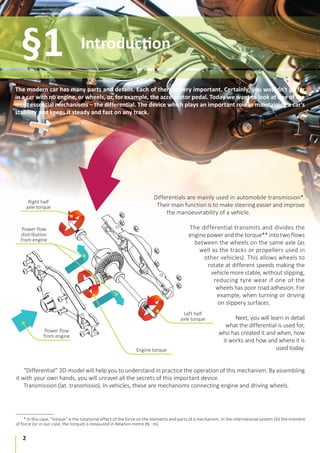
A differential is a mechanical device that transfers torque from a source to two independent drives in the way
that the rotation speed of each of those can be different.
A differential has the following properties: the Rotation power (N), torque (M), and angular velocity (ω).
Power is a scalar value that in most cases equals the rate of conversion, transmission or consumption of the
system’s energy. It is also described as a relation of the work in the period of time to that period of time.
N = A/t
In the International System of Units (SI) the base unit of the power is watt (W), named after James Watt, an
18th-century Scottish inventor.
Power is found by the formula:
N = F∙v∙cosα
In the rotation motion:
N = M ∙ ω,
Where:
М – is torque,
ω – angular velocity.
Torque can also be called “a rotating power”, N·m in the SI unit. Torque is sometimes called “moment of couple of
forces”. This term is initially found in Archimedes’ works. If the direction of the force applied to a lever is perpendicular
to it, the moment of power is found as a the amount of that power multiplied by the distance to the center of line
of rotation of the lever. For an engine it’s the rotation force of the crank shaft.
For example, the force of 3 N applied to a lever at a distance of 2 meters from the center of its line of rotation
will create the same torque as the force of 1 N applied to the lever at the distance of 3 meters from the center of
its line of rotation. The moment on point is describes as a vector multiplication:
М = [r × F]
Where:
F is a force applied to a point,
r is a vector radius of a point (if the center of rotation is at the at the origin of the coordinates).
Physics and Mechanics
explained in “Differential”
STEM-model
§4
11. 11
§4 Physics and Mechanics explained in “Differential” STEM-model
Angular velocity refers to how fast the angular position (φ) or orientation of an object changes with time. It is
represented by the symbol ω and the formula:
φ
t
=
ω
Per one revolution Δφ = 2π.
Angular velocity is related to the period of rotation and number of revolutions per period of time. It is found as:
2π
T
=
ω и ω = 2πν
As a SI unit, angular velocity is: [ω]=рад/с.
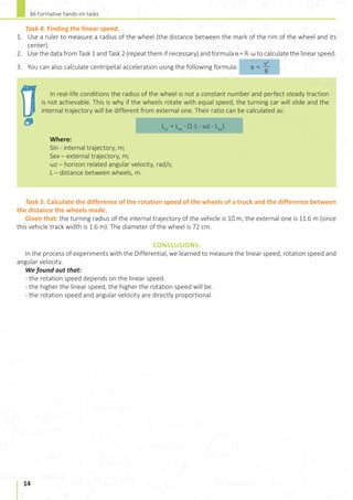
The real radius of a turn is not a constant number and perfect steady traction is not achievable. If the wheels
rotate with the same speed, the turning car will slide and the internal trajectory will be different from external
one. This difference is found as:
Lin = Lex
∙ (1-L ∙ ωz ∙ Lex
).м
Where:
Sin - internal trajectory, m;
Sex – external trajectory, m;
ωz – horizon related angular velocity, rad/s;
L – distance between wheels, m.
12. 12
Technical design
and principles of working
§5
The mechanical model of a differential is an educational aid that explains in an actual example how the device
works. It demonstrates the work of planetary gears in the distribution of load from the drive wheel to half-shafts.
Let’s consider
what the model consists of:
Wheel
Drive gear Locking
lever
Lockup
clutch
Spider
gears
In the locked position of the lever,
the energy of the motor will be equally
distributed between wheels.
Half axle
gear
Theimpulsecanbetransferredtoone
ofthewheelsorblockedbythelever.The
model comprehensively demonstrates
how a car turns with increased torque
on one wheel and lower on the other.
13. 13
Measuring rotation speed, angular and linear velocity.
Differential - the mechanism that transmits an engine’s torque to the wheels and helps to avoid wheel slip and
facilitates the work of transmission.
Objectives: to study the ways of measuring the rotation speed; to measure the rotation speed of a differential
depending on its speed, develop logic, science skills, and spatial thinking
Equipment: the Differential, a stop-watch, ruler, notepad and pen.
Theoretical background of the experiment:
The task is to measure in several different ways the rotation speed of the disc fixed on a differential’s shaft
depending on the linear speed with which it is moving. Rotational motion is found through the angular rotation φ,
rotation speed ω, angular velocity β, and time t. Every point of an object’s rotation around an axle has the same
rotation speed ω. An average rotation speed is found as:
φ
t
=
ω (1)
Angular velocity β is found through the change of the rotation speed ω in time. Therefore, the average angular
velocity formula comes as follows:
ω
t
=
β (2)
Preparation for the experiment:
Assemble the Differential and set it on a flat surface.
WORK PROGRESS:
Task 1. Finding the angular rotation.
1. Choose a point on a rim of a wheel. Mark it with a pencil.
2. Roll the Differential on a flat even surface and check how much time in took your mark to complete a full circle.
3. Use formula (1) to calculate rotation speed. For one full rotation ∆φ = 2π = 2∙1800 = 3600.
4. Repeat the experiment while rolling the Differential with a different speed.
5. Compare the values of the angular rotation and the linear speed.
Task 2. Finding the rotation speed.
1. Count the number of rotations that the mark makes in 10 seconds.
2. Calculate the rotation frequency using the formula:
N
t
=
ν
3. Calculate the rotation speed ω = 2πν.
4. Repeat the experiment while rolling the Differential with a different speed.
5. Compare your data.
Task 3. Finding the angular velocity.
1. Use data from Task 1 and Task 2 (repeat them is necessary) and formula (2) to calculate the angular velocity.
2. Compare the relationship of the angular velocity and linear speed of the differential.
Formative hands-on tasks
§6
14. 14
§6 Formative hands-on tasks
Task 4. Finding the linear speed.
1. Use a ruler to measure a radius of the wheel (the distance between the mark of the rim of the wheel and its
center).
2. Use the data from Task 1 and Task 2 (repeat them if necessary) and formula υ = R∙ ω to calculate the linear speed.
3. You can also calculate centripetal acceleration using the following formula:
v2
R
=
a .
In real-life conditions the radius of the wheel is not a constant number and perfect steady traction
is not achievable. This is why if the wheels rotate with equal speed, the turning car will slide and the
internal trajectory will be different from external one. Their ratio can be calculated as:
Lin
= Lex
∙ (1-L ∙ ωz ∙ Lex
).
Where:
Sin - internal trajectory, m;
Sex – external trajectory, m;
ωz – horizon related angular velocity, rad/s;
L – distance between wheels, m.
Task 5. Calculate the difference of the rotation speed of the wheels of a truck and the difference between
the distance the wheels made.
Given that: the turning radius of the internal trajectory of the vehicle is 10 m, the external one is 11.6 m (since
this vehicle track width is 1.6 m). The diameter of the wheel is 72 cm.
CONCLUSIONS:
In the process of experiments with the Differential, we learned to measure the linear speed, rotation speed and
angular velocity.
We found out that:
- the rotation speed depends on the linear speed.
- the higher the linear speed, the higher the rotation speed will be.
- the rotation speed and angular velocity are directly proportional.
15. 15
§6 Formative hands-on tasks
ASSESSMENT TASK
1. Credit for the first experiments with limited slip differential belongs to:
…
… а) Onesiphore Pecqueur
…
… b) Ferdinand Porsche
…
… c) Volkswagen
2. A differential provides different rotation speeds of the wheels on the same axle in order to:
…
… а) reduce speed
…
… b) reduce slip on the turn
…
… c) increase friction.
3. The improved differential is designed as:
…
… а) a gear train
…
… b) a planetary gear
…
… c) an automatic transmission
4. How many differentials do full wheel drive cars have?
…
… а) two
…
… b) three
…
… c) six.
5. What is a differential made of?
…
… а) crank shaft
…
… b) shafts and gears
…
… c) drives
6. How is rotation speed connected to the linear speed of a differential?
…
… а) it’s not connected
…
… b) increases when the linear speed increases
…
… c) decreases when the linear speed increases
7. How is angular velocity connected to the linear speed of a differential?
…
… а) via inverse proportion
…
… b) via direct proportion
…
… c) they have no connection.
8. A type of a differential in which the torque grows with increasing speed difference between the drive
and driven shafts is called:
…
… а) Torsen
…
… b) Visco drive
…
… c) Quaife
9. Which physical units characterise a differential?
…
… а) gravity, work, time
…
… b) rotation force, torque, angular velocity
…
… c) oscillation frequency, friction, linear speed
10. The unit of measurement of angular velocity is:
…
… а) m/sec
…
… b) rad/sec
…
… c) m/rad
Congratulations! You made it!
Thank you for being with us in this adventure, we hope you had fun and learned a thing or two!