Gasifi cation is a process in which combustible materials are partially oxi-dized or partially combusted. The product of gasifi cation is a combustible synthesis gas, or syngas. Because gasifi cation involves the partial, rather than complete, oxidization of the feed, gasifi cation processes operate in an oxygen-lean environment. As fi gure 1 indicates, the stoichiometric oxygen-to-coal ratio for combustion is almost four times the stoichiometric oxygen-to-coal ratio for gasifi cation of Illinois #6coal.
Gasification is a process that converts carbon-based materials like coal into a gaseous fuel called synthesis gas (syngas) through a series of chemical reactions in a gasifier. Syngas is composed primarily of carbon monoxide and hydrogen. The gasification process involves partial oxidation using oxygen and steam, producing syngas and leaving mineral residues. Key reactions in gasification include dehydration, pyrolysis, combustion, and the gasification reaction where char reacts with carbon dioxide and steam to produce carbon monoxide and hydrogen. There are three main types of gasifiers: fixed-bed, entrained-flow, and fluidized-bed gasifiers.
1) Gasification is a technology that converts solid waste into a synthetic gas (syngas) through partial oxidation reactions and has the potential to be applied in Ireland's waste industry.
2) Gasification can provide Ireland with electricity, fuels, and building materials from waste while reducing dependence on landfills and fossil fuels.
3) The paper reviews the history, chemistry, design, and environmental performance of gasification as well as its ability to produce useful products like electricity, fuels, and slag from waste processing.
The document discusses biomass gasification and different types of gasifiers. Gasification is a process that converts carbonaceous materials into a combustible gas. There are two main types of gasification gases - producer gas produced at low temperatures, and syngas produced at high temperatures. Fixed bed gasifiers like updraft, downdraft and crossdraft gasifiers as well as fluidized bed gasifiers are described. Producer gas contains more hydrocarbons while syngas contains mainly CO and H2. The applications and advantages of biomass gasification are also summarized.
Biomass is biological material derived from living, or recently living organisms. It most often refers to plants or plant-based materials which are specifically called lignocellulosic biomass.
Gasification is a process that converts biomass into syngas through partial combustion with oxygen and/or steam at high temperatures. This involves several chemical reactions: drying around 100°C, pyrolysis from 200-400°C which produces char and volatiles, and combustion and gasification reactions above 700°C which produce carbon monoxide, hydrogen, and other gases from reactions between char, steam, and carbon dioxide. Gasification has advantages over burning solid fuels as it produces a cleaner-burning fuel similar to natural gas. There are different types of gasifiers such as fixed or moving bed gasifiers and updraft or downdraft gasifiers that vary the direction of fuel and air/oxygen flow.
There are several types of gasifiers that are categorized based on flow direction and bed type. Updraft gasifiers have counter-current flow with fuel entering from the top and gasifying agents from the bottom, producing gas that exits at the top around 150°C and contains tar. Downdraft gasifiers have concurrent flow with fuel and gas moving downward and gas exiting at the bottom around 800°C where most tars are consumed. Crossdraft gasifiers introduce fuel at the bottom of a fluidized bed and produce gas with more particulates.
A short introduction to Gasification process and a brief description on various types of Gasifiers used in industries to obtain fuel and energy through this presentation.
References:-
1. http://www.enggcyclopedia.com/2012/01/types-gasifier/
2. https://en.wikipedia.org/wiki/Gasification
3. https://www.youtube.com/watch?v=GkHKXz3VaFg
4. https://www.google.co.in/
Biomass gasification involves the partial oxidation of biomass at high temperatures to produce a combustible gas mixture known as syngas. There are two main types of gasifiers - fixed bed and fluidized bed. Fixed bed gasifiers include updraft, downdraft, and crossdraft varieties which differ in how biomass and air/steam move through the reactor. Fluidized bed gasifiers suspend biomass particles in an upward-flowing stream of air/steam. Syngas must be conditioned through cooling, cleaning, and tar/pollutant removal before use. While biomass gasification provides renewable energy with fewer emissions than fossil fuels, it also faces challenges with process complexity, sensitivity, and fuel quality requirements
BIOMASS GASIFICATION,gasification and gasifier.
A slide about biomass gasification including brief description about thermo-chemical conversion process and applications
Case study on biomass gasification by shabaana me ftShahS11
This document presents a case study on biomass gasification. It provides background on biomass gasification, including that it is a process that converts solid biomass into a combustible gas through thermo-chemical reactions. It then details the specific case study conducted, which analyzed the thermoneutral points of downdraft gasification of rice husk at temperatures from 500-1000°C. The study found the reaction and process thermoneutral points, and analyzed gas composition and energy parameters at these points, both with and without a heat exchanger.
The document discusses bio gasified coupled engines which convert bio/organic fuel into producer gas or syngas that can be used to power engines. It describes the process of biomass gasification where biomass is converted into combustible gases like carbon monoxide, hydrogen, and methane through incomplete combustion. This producer gas can then be used to power gas engines or for heat applications. The document outlines the various zones in a gasifier where different chemical reactions occur during gasification and discusses reaction chemistry and technologies used.
This document discusses biomass gasification. It describes two main types of gasifiers - updraft and downdraft. Updraft gasifiers have fuel flowing downward and air/gas flowing upward, separating zones for drying, pyrolysis, combustion, and reduction. Downdraft gasifiers have fuel entering from the top and air/gas flowing downward, with pyrolysis above combustion which is above reduction. Biomass gasification converts biomass into a gaseous fuel through partial combustion and has advantages like utilizing waste and providing an alternative to fossil fuels while reducing emissions. However, it also has disadvantages like high capital costs and potential tar production.
Gasification process for generating producer gas by updraft, downdraft etc. and advantage and disadvantages of gasifier and application of producer gas for generating electricity or motive power for running the engine.
This document discusses principles of gasification and different types of gasifiers. Gasification involves partially oxidizing biomass at high temperatures to produce a gaseous fuel called producer gas. Producer gas consists mainly of combustible gases like carbon monoxide, hydrogen and methane, as well as non-combustible gases like nitrogen, carbon dioxide and water vapor. Several factors affect gasification including biomass properties and moisture content. Common types of gasifiers include updraft, downdraft, crossdraft, and fluidized bed gasifiers. Updraft gasifiers have high efficiency but produce tarry gas, while downdraft and crossdraft gasifiers produce tar-free gas but with lower efficiency. Fluidized bed gasifiers allow
Overview biomass ash in gasification systemcakbentra
Biomass gasification was initially used commercially in the 1940s and saw increased interest over the last 20 years as a renewable energy technology. There are several types of biomass gasifiers including fixed bed, fluidized bed, and entrained flow gasifiers, which vary in size and operating conditions. Major challenges for biomass gasification include ash agglomeration, fouling of heat exchangers, particulate and contaminant removal from the syngas, and proper utilization or disposal of solid residues.
The document describes a combined updraft and downdraft gasifier that was developed as part of research project in Hungary. Traditional gasifiers are very sensitive to fuel size and moisture content, but the combined gasifier can operate on a wide variety of fuels. It has a higher turn-down ratio than other designs, allowing it to efficiently produce gas from a range of fuel amounts. The gas can be used in small Otto cycle engines for applications like combined heat and power plants.
The document discusses different types of biomass gasifiers. It explains that gasifiers convert carbon-containing materials into a combustible gas through a thermo-chemical process with a restricted oxygen supply. The two main types are fixed bed and fluidized bed gasifiers. Fixed bed gasifiers include updraft, downdraft, and crossdraft types, which differ in gas and air flow directions. Updraft gasifiers produce a low-quality gas suitable only for heating while downdrafts generate a cleaner gas for engines. Fluidized beds, including bubbling and circulating types, produce higher-quality syngas but are more complex and expensive.
Research was conducted on various stove design (wood, charcoal, bricks) that could be potentially modified in stove for desired purpose. Of the stoves gasifiers and Rocket stoves were two of the core design for design work.
Environmental growth by using clean coal technology in new-
India relies heavily on coal for electricity but coal has environmental impacts. Clean coal technologies can reduce emissions. Technologies discussed include pulverized coal boilers, fluidized bed combustion, gasification, integrated gasification combined cycles, carbon capture and storage, underground coal gasification, and combined cycles. These technologies provide more efficient power generation with fewer emissions. For India, implementing supercritical plant technologies, assessing new technologies, and tightening emissions controls can help push clean coal development in the short and medium term while keeping long term technology options open. Overall clean coal technologies are promising for reducing the environmental impacts of power generation.
Episode 3 : Production of Synthesis Gas by Steam Methane ReformingSAJJAD KHUDHUR ABBAS
Episode 3 : Production of Synthesis Gas by Steam Methane Reforming
History of Synthesis Gas
In 1780, Felice Fontana discovered that combustible gas develops if water vapor is passed over carbon at temperatures over 500 °C. This CO and H2 containing gas was called water gas and mainly used for lighting purposes in the19th century.
As of the beginning of the 20th century, H2/CO-mixtures were used for syntheses of hydrocarbons and then, as a consequence, also called synthesis gas.
Haber and Bosch discovered the synthesis of ammonia from H2 and N2 in 1910 and the first industrial ammonia synthesis plant was commissioned in 1913.
The production of liquid hydrocarbons and oxygenates from syngas conversion over iron catalysts was discovered in 1923 by Fischer and Tropsch.
Much of the syngas conversion processes were being developed in Germany during the first and second world wars at a time when natural resources were becoming scare and alternative routes for hydrogen production, ammonia synthesis, and transportation fuels were a necessity.
In 1943/44, this was applied for large-scale production of artificial fuels from synthesis gas in Germany.
This document discusses coal gasification, which involves converting coal into a gaseous fuel called synthesis gas (syngas) through a process of partial oxidation. Syngas is composed primarily of carbon monoxide and hydrogen. There are three main types of gasifiers - moving bed, entrained flow, and fluidized bed. Catalytic gasification uses catalysts to lower operating temperatures and enhance reaction rates. Applications of syngas include power generation, chemical production, hydrogen production, and byproducts like ash for construction materials. Further research is needed to develop carbon capture technologies and more efficient oxygen separation methods to enable cleaner coal gasification processes.
Production of Syngas from biomass and its purificationAwais Chaudhary
This document summarizes a project proposal for a biomass gasification plant in Pakistan. It discusses the motivation, basic chemistry, advantages of syngas, availability of raw materials, effects of temperature and residence time on syngas production, particulate matter, tars, sulfur, nitrogen compounds in biomass gasification. It also describes the gasification process selected, purification of syngas using hot gas cleanup technology, equipment list, environmental considerations, and concludes with recommendations for syngas production from biomass.
The document discusses thermodynamic analysis of biomass gasification. It analyzes the reaction thermoneutral points (R-TNPs) for gasifying rice husk with different gasifying agents and their ratios. Key findings include:
- For CO2 alone, R-TNPs decreased with higher CO2:carbon ratios, with syngas output and CO2 conversion also decreasing. Heat requirements initially rose then fell with a heat exchanger.
- R-TNPs were not found for H2O alone at any ratio.
- With CO2+H2O, R-TNPs were only obtained at low total gasifier agent:carbon ratios. Higher ratios supported
The document discusses the fundamentals of biomass combustion, including the processes of drying, pyrolysis, flaming combustion, and glowing combustion. It also covers combustion equipment designs like inclined grate furnaces, spreader stokers, cyclonic and suspension fired systems, and fluidized bed combustion. The goal of combustion system design is to efficiently oxidize the biomass through sufficient mixing of the fuel with oxygen and controlling residence times and temperatures.
The document describes a gasification process that involves multiple steps. Waste is fed into a combustion chamber heated to 1000°C to produce fuel gas. The gas then passes through a melting pot heated to 1400°C to remove heavy metals. Emissions are treated through a wet scrubber, SCR system, and bag and HEPA filters before being discharged. Operational temperatures at different levels of the process are listed, along with diagrams of equipment like the waste heat boiler and melting pot structure.
The document discusses a method for producing synthesis gas (syngas) from gasification of bagasse. Bagasse is a waste product from sugar production that is abundant in India. Syngas produced from bagasse gasification can be used as an alternative fuel source for power generation and other industrial processes. The method involves pyrolyzing bagasse in a free-fall reactor to produce char, and then gasifying the char in a packed bed reactor to produce syngas, which consists mainly of carbon monoxide and hydrogen. Experimental results show that syngas yield increases with higher temperature and smaller bagasse particle size during pyrolysis.
1. Gas-based direct reduced iron (DRI) production using syngas from coal gasification is more energy efficient and environmentally friendly than coal-based DRI. High metallization, carbon content, and low gangue in the DRI influence lower energy consumption.
2. Key operating parameters of a coal gas-based DRI plant were studied and optimized, including reducing gas quality, composition, temperature and flow rates to maximize plant performance.
3. The reducing gas composition, bustle gas temperature, and methane concentration must be carefully controlled to manage the DRI carbon content and metallization through complex chemical reactions during production.
The document discusses coal gasification and integrated gasification combined cycle (IGCC) power plants. Key points:
- IGCC power plants use coal gasification followed by a gas turbine and steam turbine process to achieve net efficiencies over 55% and allow for easier CO2 separation than conventional coal plants.
- Germany has invested over 400 million euros in over 100 projects on gasification technology over the past 30 years to further develop IGCC technology and make it more cost-effective.
- IGCC power plants have significantly higher efficiencies and lower emissions than conventional coal plants. Research aims to further increase efficiencies and reduce costs to make IGCC competitive with other low-CO2 power generation options.
This document discusses high efficiency electric power generation technologies. It reviews electric power plant efficiency and how efficiency improvements can reduce all emissions, including carbon dioxide, without additional environmental equipment. Higher efficiency is the most practical way to currently reduce CO2 emissions from fossil fuel plants. Advanced steam, gas turbine, and coal gasification combined cycle plants that can achieve over 50% efficiency are discussed and compared. Supercritical and ultra-supercritical steam plants burning pulverized coal are highlighted as mature, high efficiency options for new plants and upgrades.
The document discusses hydrogen production via steam reforming of natural gas. Steam reforming involves four steps: reforming, shift conversion, gas purification, and methanation. It produces hydrogen at high efficiency and is the lowest cost production method currently available. However, it also produces carbon dioxide as a byproduct. Newer steam reforming plants use pressure swing absorption to produce 99.99% pure hydrogen. While steam reforming is an efficient process, it contributes to carbon dioxide emissions, so methods to capture and store the CO2 are being investigated.
This is a report on the design of a plant to produce 20 million standard cubic feet per day (0.555 × 10⁶ standard m3/day) of hydrogen (H2) of at least 95% purity from heavy fuel oil (HFO) with an upstream time of 7680 hours/year applying the process of partial oxidation of the heavy oil feedstock.
Increasing the temperature in the Gibbs reactor from 800°C to 5000°C:
- Hydrogen production increases significantly, reaching a maximum around 1600°C then decreasing.
- Carbon monoxide production also increases to a maximum at 1600°C then decreases with further temperature rise.
- Carbon dioxide production decreases steadily as temperature increases.
- Methane production increases slightly with temperature over most of the range tested.
This document discusses steam methane reformers used in hydrogen, ammonia, and methanol plants. It describes the basic steam methane reforming process where methane and steam are reacted over a nickel catalyst at high temperatures to produce hydrogen and a mixture of CO and CO2. It discusses the desired and unwanted reactions that can occur and factors that affect conversion such as temperature, pressure, steam to carbon ratio, and catalyst activity. It also describes different reformer furnace configurations and profiles of temperature, heat flux, and conversion along the tubes. Finally, it discusses stresses on reformer tubes and improvements in materials over time that have allowed for thinner tubes with the same lifetime.
Minimising emissions, maximising alternative fuelsA TEC Group
Dr. Stefan Kern, A TEC Production and Services GmbH, details the conversion of the kiln at Lafarge Retznei and shows how an optimised calciner design allowed for 100% alternative fuel usage.
"Minimising emissions, maximising alternative fuels". Article published on World Cement Magazine, edition June 2022.
The document discusses various technologies for producing hydrogen and synthesis gas, including steam reforming, partial oxidation, coal gasification, and water electrolysis. It provides an overview of the main industrial processes used for ammonia synthesis gas production, noting that about 85% is based on steam reforming of natural gas or other light hydrocarbons. Various hydrogen and syngas production processes are also compared in terms of energy consumption, investment cost, and production cost.
This document summarizes a new process for converting coal to ammonia using Kellogg Brown & Root's (KBR) Transport Reactor Integrated Gasifier (TRIG) technology. The process involves:
1. Gasifying coal using KBR's TRIG technology to produce syngas. The syngas is then purified through steps like acid gas removal.
2. Compressing the purified syngas and feeding it into an ammonia synthesis loop to produce ammonia using a conventional KBR ammonia process.
3. Recovering the ammonia produced and refrigerating it for storage or transport.
The paper provides details on the major unit operations in the coal gasification and ammonia
Synthetic gas (syngas) can be produced from gasification of biomass, coal, or natural gas reforming and contains mainly carbon monoxide (CO) and hydrogen (H2). The key properties that affect combustion include the flammability limits and laminar flame velocity. Syngas is commonly produced via gasification processes involving partial oxidation of carbon-based feedstocks with oxygen, steam, or carbon dioxide at high temperatures. The syngas can then be used to produce fuels and chemicals through processes like Fischer-Tropsch synthesis, which converts syngas into liquid hydrocarbons. Removal of impurities from the raw syngas produced is typically required before it can be used as a chemical
The document discusses natural gas liquid (NGL) recovery from natural gas streams. It covers key terms, factors that affect recovery like gas composition and sales gas specifications, various process options for NGL recovery like low temperature separation and straight refrigeration, and provides an example problem calculating recovery values.
Three main methods are used to remove nitrogen from natural gas: cryogenic distillation, adsorption, and membrane separation. Cryogenic distillation involves using low temperatures and pressures to separate gas components. It is most effective at recovering ethane, propane, butane, and natural gasoline. Adsorption uses materials like molecular sieves to attract moisture and other compounds from the gas stream. Membrane separation exploits differences in molecular sizes to selectively permeate some components over others.
This document discusses nitrogen removal from natural gas feedstock for chemicals production. It notes that nitrogen needs to be removed, as its presence would dilute reactants and increase costs. Cryogenic distillation is identified as the most economical method for large-scale nitrogen removal, as it is energy efficient and can process large volumes. Modern cryogenic nitrogen removal plants typically use a two-stage distillation process to produce high purity methane and nitrogen. They optimize energy usage to minimize operating costs. The document recommends upstream nitrogen removal for gas with over 3% nitrogen, as downstream separation would be less efficient. It also notes the importance of fully removing hydrocarbons from vented nitrogen due to environmental regulations.
This document discusses hydrogen production via steam reforming with CO2 capture. It examines the possibilities of capturing CO2 from a steam reforming hydrogen plant. There are three main locations where CO2 can be captured: 1) from the raw hydrogen stream before purification, 2) from the purge gas stream after purification, and 3) from the steam reformer flue gas. Capturing from the raw hydrogen and flue gas streams can achieve overall CO2 removal rates of 60% and 90%, respectively. Amine-based capture is commonly used for the raw hydrogen and flue gas streams. A case study found the cost of capturing from the flue gas to be higher than from the raw hydrogen stream, and in both cases the
The document describes the modified Claus process for sulfur recovery. It discusses the basic Claus reaction and how the modified process improved on it with a free flame oxidation ahead of the catalyst bed and catalytic step revisions, allowing for higher sulfur recovery efficiencies of 90-99.9%. The key steps of the modified Claus process are presented as the combustion step and multiple catalytic steps. Process variations like the straight-through and split-flow configurations are described along with tail gas handling and other sulfur removal processes. Sample calculations are provided to determine the optimum operating parameters for a 80 long ton per day sulfur recovery unit using the modified Claus process.
Hydrogen production via steam reforming of natural gas is the most common and economical method. It involves four steps: reforming of methane and steam into hydrogen and carbon monoxide, shift conversion to further increase hydrogen, gas purification to remove carbon dioxide, and methanation to convert remaining carbon oxides to methane. Newer plants use pressure swing adsorption instead of wet scrubbing for high purity hydrogen. Partial oxidation of heavier feeds is also possible but more expensive due to needing oxygen.
The primary reformer is where natural gas and steam undergo endothermic reforming reactions to produce hydrogen. Approximately 80% of an ammonia plant's fuel is consumed in the primary reformer burners heating these reactions. To optimize performance, the furnace draft, oxygen content in flue gases, and reformer outlet temperature must be maintained within optimal ranges. High or low draft, excess or insufficient oxygen, and temperatures too low or too high can all decrease efficiency. Careful control of these factors is required for efficient and safe primary reformer operation.
Generative AI Use cases applications solutions and implementation.pdfmahaffeycheryld
Generative AI solutions encompass a range of capabilities from content creation to complex problem-solving across industries. Implementing generative AI involves identifying specific business needs, developing tailored AI models using techniques like GANs and VAEs, and integrating these models into existing workflows. Data quality and continuous model refinement are crucial for effective implementation. Businesses must also consider ethical implications and ensure transparency in AI decision-making. Generative AI's implementation aims to enhance efficiency, creativity, and innovation by leveraging autonomous generation and sophisticated learning algorithms to meet diverse business challenges.
https://www.leewayhertz.com/generative-ai-use-cases-and-applications/
Embedded machine learning-based road conditions and driving behavior monitoringIJECEIAES
Car accident rates have increased in recent years, resulting in losses in human lives, properties, and other financial costs. An embedded machine learning-based system is developed to address this critical issue. The system can monitor road conditions, detect driving patterns, and identify aggressive driving behaviors. The system is based on neural networks trained on a comprehensive dataset of driving events, driving styles, and road conditions. The system effectively detects potential risks and helps mitigate the frequency and impact of accidents. The primary goal is to ensure the safety of drivers and vehicles. Collecting data involved gathering information on three key road events: normal street and normal drive, speed bumps, circular yellow speed bumps, and three aggressive driving actions: sudden start, sudden stop, and sudden entry. The gathered data is processed and analyzed using a machine learning system designed for limited power and memory devices. The developed system resulted in 91.9% accuracy, 93.6% precision, and 92% recall. The achieved inference time on an Arduino Nano 33 BLE Sense with a 32-bit CPU running at 64 MHz is 34 ms and requires 2.6 kB peak RAM and 139.9 kB program flash memory, making it suitable for resource-constrained embedded systems.
Software Engineering and Project Management - Introduction, Modeling Concepts...Prakhyath Rai
Introduction, Modeling Concepts and Class Modeling: What is Object orientation? What is OO development? OO Themes; Evidence for usefulness of OO development; OO modeling history. Modeling
as Design technique: Modeling, abstraction, The Three models. Class Modeling: Object and Class Concept, Link and associations concepts, Generalization and Inheritance, A sample class model, Navigation of class models, and UML diagrams
Building the Analysis Models: Requirement Analysis, Analysis Model Approaches, Data modeling Concepts, Object Oriented Analysis, Scenario-Based Modeling, Flow-Oriented Modeling, class Based Modeling, Creating a Behavioral Model.
Applications of artificial Intelligence in Mechanical Engineering.pdfAtif Razi
Historically, mechanical engineering has relied heavily on human expertise and empirical methods to solve complex problems. With the introduction of computer-aided design (CAD) and finite element analysis (FEA), the field took its first steps towards digitization. These tools allowed engineers to simulate and analyze mechanical systems with greater accuracy and efficiency. However, the sheer volume of data generated by modern engineering systems and the increasing complexity of these systems have necessitated more advanced analytical tools, paving the way for AI.
AI offers the capability to process vast amounts of data, identify patterns, and make predictions with a level of speed and accuracy unattainable by traditional methods. This has profound implications for mechanical engineering, enabling more efficient design processes, predictive maintenance strategies, and optimized manufacturing operations. AI-driven tools can learn from historical data, adapt to new information, and continuously improve their performance, making them invaluable in tackling the multifaceted challenges of modern mechanical engineering.
Use PyCharm for remote debugging of WSL on a Windo cf5c162d672e4e58b4dde5d797...shadow0702a
This document serves as a comprehensive step-by-step guide on how to effectively use PyCharm for remote debugging of the Windows Subsystem for Linux (WSL) on a local Windows machine. It meticulously outlines several critical steps in the process, starting with the crucial task of enabling permissions, followed by the installation and configuration of WSL.
The guide then proceeds to explain how to set up the SSH service within the WSL environment, an integral part of the process. Alongside this, it also provides detailed instructions on how to modify the inbound rules of the Windows firewall to facilitate the process, ensuring that there are no connectivity issues that could potentially hinder the debugging process.
The document further emphasizes on the importance of checking the connection between the Windows and WSL environments, providing instructions on how to ensure that the connection is optimal and ready for remote debugging.
It also offers an in-depth guide on how to configure the WSL interpreter and files within the PyCharm environment. This is essential for ensuring that the debugging process is set up correctly and that the program can be run effectively within the WSL terminal.
Additionally, the document provides guidance on how to set up breakpoints for debugging, a fundamental aspect of the debugging process which allows the developer to stop the execution of their code at certain points and inspect their program at those stages.
Finally, the document concludes by providing a link to a reference blog. This blog offers additional information and guidance on configuring the remote Python interpreter in PyCharm, providing the reader with a well-rounded understanding of the process.
Rainfall intensity duration frequency curve statistical analysis and modeling...bijceesjournal
Using data from 41 years in Patna’ India’ the study’s goal is to analyze the trends of how often it rains on a weekly, seasonal, and annual basis (1981−2020). First, utilizing the intensity-duration-frequency (IDF) curve and the relationship by statistically analyzing rainfall’ the historical rainfall data set for Patna’ India’ during a 41 year period (1981−2020), was evaluated for its quality. Changes in the hydrologic cycle as a result of increased greenhouse gas emissions are expected to induce variations in the intensity, length, and frequency of precipitation events. One strategy to lessen vulnerability is to quantify probable changes and adapt to them. Techniques such as log-normal, normal, and Gumbel are used (EV-I). Distributions were created with durations of 1, 2, 3, 6, and 24 h and return times of 2, 5, 10, 25, and 100 years. There were also mathematical correlations discovered between rainfall and recurrence interval.
Findings: Based on findings, the Gumbel approach produced the highest intensity values, whereas the other approaches produced values that were close to each other. The data indicates that 461.9 mm of rain fell during the monsoon season’s 301st week. However, it was found that the 29th week had the greatest average rainfall, 92.6 mm. With 952.6 mm on average, the monsoon season saw the highest rainfall. Calculations revealed that the yearly rainfall averaged 1171.1 mm. Using Weibull’s method, the study was subsequently expanded to examine rainfall distribution at different recurrence intervals of 2, 5, 10, and 25 years. Rainfall and recurrence interval mathematical correlations were also developed. Further regression analysis revealed that short wave irrigation, wind direction, wind speed, pressure, relative humidity, and temperature all had a substantial influence on rainfall.
Originality and value: The results of the rainfall IDF curves can provide useful information to policymakers in making appropriate decisions in managing and minimizing floods in the study area.
Gas agency management system project report.pdfKamal Acharya
The project entitled "Gas Agency" is done to make the manual process easier by making it a computerized system for billing and maintaining stock. The Gas Agencies get the order request through phone calls or by personal from their customers and deliver the gas cylinders to their address based on their demand and previous delivery date. This process is made computerized and the customer's name, address and stock details are stored in a database. Based on this the billing for a customer is made simple and easier, since a customer order for gas can be accepted only after completing a certain period from the previous delivery. This can be calculated and billed easily through this. There are two types of delivery like domestic purpose use delivery and commercial purpose use delivery. The bill rate and capacity differs for both. This can be easily maintained and charged accordingly.
Build the Next Generation of Apps with the Einstein 1 Platform.
Rejoignez Philippe Ozil pour une session de workshops qui vous guidera à travers les détails de la plateforme Einstein 1, l'importance des données pour la création d'applications d'intelligence artificielle et les différents outils et technologies que Salesforce propose pour vous apporter tous les bénéfices de l'IA.
Comparative analysis between traditional aquaponics and reconstructed aquapon...bijceesjournal
The aquaponic system of planting is a method that does not require soil usage. It is a method that only needs water, fish, lava rocks (a substitute for soil), and plants. Aquaponic systems are sustainable and environmentally friendly. Its use not only helps to plant in small spaces but also helps reduce artificial chemical use and minimizes excess water use, as aquaponics consumes 90% less water than soil-based gardening. The study applied a descriptive and experimental design to assess and compare conventional and reconstructed aquaponic methods for reproducing tomatoes. The researchers created an observation checklist to determine the significant factors of the study. The study aims to determine the significant difference between traditional aquaponics and reconstructed aquaponics systems propagating tomatoes in terms of height, weight, girth, and number of fruits. The reconstructed aquaponics system’s higher growth yield results in a much more nourished crop than the traditional aquaponics system. It is superior in its number of fruits, height, weight, and girth measurement. Moreover, the reconstructed aquaponics system is proven to eliminate all the hindrances present in the traditional aquaponics system, which are overcrowding of fish, algae growth, pest problems, contaminated water, and dead fish.
Comparative analysis between traditional aquaponics and reconstructed aquapon...
Different types of gasifiers
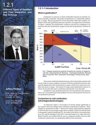
1. 6767
1.2.1-1 Introduction
What is gasification?
Gasification is a process in which combustible materials are partially oxi-
dized or partially combusted. The product of gasification is a combustible synthesis
gas, or syngas. Because gasification involves the partial, rather than complete, oxi-
dization of the feed, gasification processes operate in an oxygen-lean environment.
As figure 1 indicates, the stoichiometric oxygen-to-coal ratio for combustion is al-
most four times the stoichiometric oxygen-to-coal ratio for gasification of Illinois #6
coal.
Just as most combustion-based processes such as power plants operate with
excess oxygen to ensure complete conversion of the fuel, gasification processes also
typically operate above their stoichiometric oxygen-to-fuel ratio to ensure near com-
plete conversion to syngas. The amount of oxygen used in gasification, however, is
always far less than that used in combustion and typically is less than half.
In addition to coal, gasification processes can use petroleum coke, biomass,
heavy oil, or even natural gas as the feedstock; however, this document will focus on
coal gasification processes.
Comparison to coal combustion
(advantages/disadvantages)
As indicated in figure 1, the products of reaction change significantly as
the oxygen-to-fuel ratio changes from combustion to gasification conditions. These
changes are summarized in table 1. Because the mixture under gasifying conditions
is fuel-rich, there are not enough oxygen atoms available to fully react with the feed.
Consequently, instead of producing CO2
, the carbon in the feed is converted primar-
ily to CO, and the hydrogen in the fuel is converted mostly to H2
rather than H2
O.
Both CO and H2
are excellent fuels for use in a combustion turbine; however, their
combustion characteristics are significantly different from natural gas.
1.2.1
Fig. 1. Diagram showing the products of reaction as a function of oxygen-to-
coal ratio ( Reprinted from M. Ramezan, “Coal-based Gasification Technolo-
gies: An Overview” NETL Gasification Technologies Training Course, Sept.
2004.)
Different Types of Gasifiers
and Their Integration with
Gas Turbines
Jeffrey Phillips
EPRI / Advanced Coal Generation
P.O. Box 217097
Charlotte, NC 28221
phone: (704) 595-2250
email: jphillip@epri.com
2. 68
Table 1 Comparison of the primary products created by the
main fuel constituents in combustion and gasification
the hydrogen in the fuel is converted mostly to H2 rather than H2O. Both CO and H2 are excellent fuels for
use in a combustion turbine; however, their combustion characteristics are significantly different from
natural gas. The implications of this will be fully covered in Section 3.1.
����� � Comparison of the primary products created by the main fuel constituents in combustion and
gasification
���������� ������������
Carbon CO2 CO
Hydrogen H2O H2
Nitrogen NO, NO2 HCN, NH3 or N2
Sulfur SO2 or SO3 H2S or COS
Water H2O H2
The fate of the fuel’s nitrogen and sulfur in a gasification process has important and beneficial
consequences on the environmental performance of an IGCC. Fuel-bound nitrogen, which is
predominantly converted to NOx in combustion, is converted to N2, NH3 or HCN in gasification. As
discussed in the “Syngas Clean-up Requirements” section of this chapter, both NH3 and HCN can be
removed to very low levels with the resulting cleaned syngas having essentially no fuel-bound nitrogen.
This significantly limits NOx emissions of an IGCC.
The sulfur in fuel produces SOx in combustion processes but is converted to H2S and COS in gasification
conditions. As will be described further on, both H2S and COS can be removed from the syngas using
technology developed for the natural gas industry to levels of less than 20 ppm, which means that more
than 99% of the sulfur can be removed from the fuel and will not be emitted as SOx.
Another major difference between combustion and gasification is the amount of heat that is released by the
chemical reactions. In combustion, all of the fuel’s chemical energy is released as heat (assuming it is fully
converted), but in gasification most of the fuel’s chemical energy is not released as heat. In fact, an
important measure of the efficiency of a gasification process is the fraction of the feedstock’s chemical
energy, or heating value, which remains in the product syngas. This fraction is termed the “cold gas
efficiency,” and most commercial-scale gasification processes have a cold gas efficiency of at least 65%
and some exceed 80%.
Because significantly less heat is released by the gasification process, it is important to limit the amount of
heat that is transferred out of the zone where the gasification reactions are occurring. If not, the
temperatures within the gasification zone could be too low to allow the reactions to go forward (a minimum
of 1000ºC or 1800ºF is typically needed to gasify coal). Consequently, unlike a boiler where the entire
firebox is lined with water-filled tubes that capture the heat released by the process and produce steam,
many gasifiers are refractory-lined with no water cooling to ensure as little heat loss as possible. Gasifiers
also typically operate at elevated pressure, sometimes as high as 6.2 MPa (900 psia), which allows them to
have very compact construction with minimum surface area and minimal heat loss.
������� ������� ����� �� ���������
������ ���
A diagram of a generic moving bed gasifier is shown in Fig. 2. Moving bed gasifiers are countercurrent
flow reactors in which the coal enters at the top of the reactor and air or oxygen enters at the bottom. As
the coal slowly moves down through the reactor, it is gasified and the remaining ash drops out of the
bottom of the reactor.
Because of the countercurrent flow arrangement, the heat of reaction from the gasification reactions serves
to pre-heat the coal before it enters the gasification reaction zone. Consequently, the temperature of the
syngas exiting the gasifier is significantly lower than the temperature needed for complete conversion of
the coal.
The fate of the fuel’s nitrogen and sulfur in a gasification process has important and beneficial consequences on the environ-
mental performance of an IGCC. Fuel-bound nitrogen, which is predominantly converted to NOx in combustion, is converted to N2
,
NH3
or HCN in gasification. As discussed in the “Syngas Clean-up Requirements” section of this chapter, both NH3
and HCN can be
removed to very low levels with the resulting cleaned syngas having essentially no fuel-bound nitrogen. This significantly limits NOx
emissions of an IGCC.
The sulfur in fuel produces SOx
in combustion processes but is converted to H2
S and COS in gasification conditions. As will
be described further on, both H2
S and COS can be removed from the syngas using technology developed for the natural gas industry
to levels of less than 20 ppm, which means that more than 99% of the sulfur can be removed from the fuel and will not be emitted as
SOx
.
Another major difference between combustion and gasification is the amount of heat that is released by the chemical reactions.
In combustion, all of the fuel’s chemical energy is released as heat (assuming it is fully converted), but in gasification most of the fuel’s
chemical energy is not released as heat. In fact, an important measure of the efficiency of a gasification process is the fraction of the
feedstock’s chemical energy, or heating value, which remains in the product syngas. This fraction is termed the “cold gas efficiency,”
and most commercial-scale gasification processes have a cold gas efficiency of at least 65% and some exceed 80%.
Because significantly less heat is released by the gasification process, it is important to limit the amount of heat that is trans-
ferred out of the zone where the gasification reactions are occurring. If not, the temperatures within the gasification zone could be too
low to allow the reactions to go forward (a minimum of 1000o
C or 1800o
F is typically needed to gasify coal). Consequently, unlike a
boiler where the entire firebox is lined with water-filled tubes that capture the heat released by the process and produce steam, many
gasifiers are refractory-lined with no water cooling to ensure as little heat loss as possible. Gasifiers also typically operate at elevated
pressure, sometimes as high as 6.2 MPa (900 psia), which allows them to have very compact construction with minimum surface area
and minimal heat loss.
1.2.1-2 Generic Types of Gasifiers
Moving Bed
A diagram of a generic moving bed gasifier is shown in figure 2. Moving bed gasifiers are countercurrent flow reactors in which
the coal enters at the top of the reactor and air or oxygen enters at the bottom. As the coal slowly moves down through the reactor, it
is gasified and the remaining ash drops out of the bottom of the reactor. Because of the countercurrent flow arrangement, the heat of
reaction from the gasification reactions serves to pre-heat the coal before it enters the gasification reaction zone. Consequently, the
temperature of the syngas exiting the gasifier is significantly lower than the temperature needed for complete conversion of the coal.
Fig. 2. Diagram of a generic moving bed gasifier
3. 69
The residence time of the coal within a moving bed gasifier may be on the order of hours.
Moving bed gasifiers have the following characteristics:1
• Low oxidant requirements;
• Relatively high methane content in the produced gas;
• Production of hydrocarbon liquids, such as tars an oils;
• High “cold gas” thermal efficiency when the heating value of the hydrocarbon liquids are included;
• Limited ability to handle fines; and
• Special requirements for handling caking coal.
Fluidized Bed
A diagram of a generic fluidized bed gasifier is shown in figure 3. A fluidized bed gasifier is a back-mixed or well-stirred reac-
tor in which there is a consistent mixture of new coal particles mixed in with older, partially gasified and fully gasified particles. The
mixing also fosters uniform temperatures throughout the bed. The flow of gas into the reactor (oxidant, steam, recycled syngas) must
be sufficient to float the coal particles within the bed but not so high as to entrained them out of the bed. However, as the particles are
gasified, they will become smaller and lighter and will be entrained out of the reactor. It is also important that the temperatures within
the bed are less than the initial ash fusion temperature of the coal to avoid particle agglomeration.
Typically a cyclone downstream of the gasifier will capture the larger particles that are entrained out and these particles are
recycled back to the bed. Overall, the residence time of coal particles in a fluidized bed gasifier is shorter than that of a moving bed
gasifier.
Fig. 3. Diagram of a generic fluidized bed gasifier
Generic characteristics of fluidized bed gasifiers include:2
• Extensive solids recycling;
• Uniform and moderate temperature; and
• Moderate oxygen and steam requirements.
Entrained Flow
A diagram of a generic entrained flow gasifier is shown in figure 4. Finely-ground coal is injected in co-current flow with the
oxidant. The coal rapidly heats up and reacts with the oxidant. The residence time of an entrained flow gasifier is on the order of sec-
onds or tens of seconds. Because of the short residence time, entrained flow gasifiers must operate at high temperatures to achieve high
carbon conversion. Consequently, most entrained flow gasifiers use oxygen rather than air and operate above the slagging temperature
of the coal.
Generic characteristics of entrained flow gasifiers include:3
• High-temperature slagging operation;
• Entrainment of some molten slag in the raw syngas;
• Relatively large oxidant requirements;
• Large amount of sensible heat in the raw syngas; and
• Ability to gasify all coal regardless of rank, caking characteristics or amount of fines.
Jeffrey Phillips
4. 70
Fig. 4. Diagram of a generic entrained flow gasifier
Hybrid & Novel Gasifiers
In addition to the three main classifications of gasifier types (moving bed, fluidized bed, and entrained flow) there are also gas-
ifiers that are based on either hybrid combinations of those three classifications or novel processes such as a molten metal bath.
The transport reactor-based gasifier developed by Kellogg Brown & Root (KBR) is an example of a hybrid gasifier as it has
characteristics of both a fluidized bed and an entrained flow gasifier. The KBR gasifier will be described in more detail in the sub-section
covering “pre-commercial” gasifiers.
1.2.1-3 Other Design Options
In addition to the generic reactor designs of a gasification process, there are several other design options that a gasification
process can have. Each of these options can have important impacts on the downstream processes in an IGCC including the combined
cycle.
Atmospheric vs Pressurized
Gasifiers can operate at either atmospheric pressure or at pressures as high as 62 bar (900 psia). Pressurized gasifiers are better
suited for IGCC operation since the pressure of product syngas will be sufficient to be fed directly into the GT fuel control system. Low
pressure or atmospheric pressure gasifiers will require a fuel gas compressor after the syngas clean-up processes.
High pressure gasifiers also have a positive impact on the cost and performance of the syngas clean-up section. Because the
volumetric flow of the syngas is much smaller than it would be for an atmospheric process, the size of the clean-up equipment is smaller.
For example, Hg capture can be accomplished by passing the syngas through a sulfur-impregnated, activated carbon bed. The size of
the bed is dictated by the residence time of the syngas in the bed. Therefore, a smaller volumetric flow of syngas will result in a smaller
carbon bed.
If CO2
capture is required in future IGCCs, high pressure gasifier operation will improve the performance of physical absorp-
tion processes that can remove CO2
from the syngas.
Dry Feed vs Slurry Feed
Coal is typically fed into a pressurized gasifier either pneumatically as a dry solid or pumped as coal-water slurry. Slurry-fed
feed systems have a lower capital cost, but result in less efficient conversion of coal to syngas (referred to as the “cold gas efficiency”
of the gasifier). This is because some of the syngas must be “burned” in order to generate the heat needed to vaporize the water in the
slurry. Consequently, the syngas produced by a slurry-fed gasifier typically has more CO2
in it than a dry-fed gasifier. This is not det-
rimental to GT operations since the CO2
can act as an effective diluent for NOx control; however, it does impact the design of the “acid
gas removal” section of the IGCC as that process must use a solvent which allows the CO2
to pass through with the syngas rather than
being stripped out with the sulfur species.
Air-blown versus Oxygen-blown
Oxygen for the gasification reactions can be provided by either air or high purity oxygen produced by a cryogenic air separation
unit (ASU). Air-blown gasifiers avoid the large capital cost of an ASU but produce a much lower calorific value syngas than oxygen-
blown gasifiers. The nitrogen in the air typically dilutes the syngas by a factor of 3 compared to oxygen-blown gasification. Therefore,
while a syngas calorific value of 300 Btu/scf might be typical from an oxygen-blown gasifier, an air-blown gasifier will typically produce
syngas with a calorific value of 100 Btu/scf. This has a significant impact on the design of the combustion system of the GT.
Because the nitrogen in air must be heated to the gasifier exit temperature by burning some of the syngas, air-blown gasification
is more favorable for gasifiers which operate at lower temperatures (i.e. non-slagging).
Different Types of Gasifiers and Their Integration with Gas Turbines1.2.1
5. 71
Air-blown gasifiers also have a negative impact on CO2
capture. Because of the dilution effect of the nitrogen, the partial
pressure of CO2
in air-blown gasifier syngas will be one-third of that from an oxygen-blown gasifier. This increases the cost and
decreases the effectiveness of the CO2
removal equipment.
Quench versus Heat Recovery
A final design option involves the method for cooling the syngas produced by the gasifier. Regardless of the type of gasifier,
the exiting syngas must be cooled down to approximately 100o
C in order to utilize conventional acid gas removal technology. This
can be accomplished either by passing the syngas through a series of heat exchangers which recover the sensible heat for use in the
steam cycle of the IGCC, or by directly contacting the syngas with relatively cool water. This latter process is called a “quench” and
it results in some of the quench water being vaporized and mixed with the syngas. The quenched syngas is saturated with water and
must pass through a series of condensing heat exchanges which remove the moisture from the syngas (so it can be recycled to the
quench zone).
Quench designs have a negative impact on the heat rate of an IGCC as the sensible heat of the high temperature syngas is
converted to low level process heat rather than high pressure steam. However, quench designs have much lower capital costs and can
be justified when low cost feedstock is available. Quench designs also have an advantage if CO2
capture is desired. The saturated
syngas exiting a quench section has near the optimum H2
O/CO ratio for feed into a water-gas shift catalyst which will convert the CO
in the syngas to CO2
. Non-quench designs that require CO2
capture will have to add steam to the syngas before it is sent to a water-gas
shift reactor.
1.2.1-4 Integrating with a Combined Cycle
Syngas Clean-Up Requirements
Before syngas can be fed to a GT, it must pass through a series of clean-up steps in order to remove species that would either
harm the environment or the GT itself.
Particulate Matter qualifies as being both bad for the environment and the gas turbine. Particulates can be removed by “dry”
processes such as a cyclone and rigid barrier filter or by “wet” processes such as a venturi scrubber.
Gas turbines are fairly tolerant of sulfur species in the fuel. A typical OEM specification will call for no more than 250 ppmv
of sulfur in the fuel. Concentrations of sulfur greater than that will cause unacceptably rapid corrosion of hot section parts. Even
250 ppmv of sulfur in the fuel would result in a relatively high sulfuric acid dewpoint in the exhaust gas. This would limit the amount
of heat that could be recovered from the exhaust in the HRSG. To allow stack gas temperatures that are typical of natural gas fired
combined cycles, the sulfur content of the syngas should be no more than 30 ppmv.
A coal with 1wt. % sulfur will typically produce a syngas with 3000 ppmv sulfur. Obviously a sulfur removal step is required
in order to meet the OEM’s fuel sulfur specification. As described earlier, well-proven technologies from the natural gas industry ex-
ist that can remove more than 99% of the H2
S and COS in the syngas. This also allows IGCCs to beat US New Source Performance
Standards for sulfur emissions from coal-fueled power plants by a comfortable margin.
Nitrogen-containing species other than N2
must be removed to a low level to prevent formation of “fuel-bound NOx
” in the
GT combustor. HCN and NH3
concentrations typically are on the order of hundreds of ppmv in raw syngas. Because of its high solu-
bility in water, NH3
can be easily washed out of the syngas by contacting it with water in a counter-flow packed column (the water then
must be treated with neutralizing chemicals). Catalysts have been developed which promote the reaction of HCN with water vapor to
produce NH3
and CO. Therefore, a HCN conversion catalyst is typically installed upstream of the NH3
water wash column.
Chlorides must be removed from the syngas to prevent corrosion in the GT hot section. HCl is quite soluble in water, and
therefore the same water wash which removes NH3
for NOx control, will also remove chlorides to an acceptable level.
While it is not necessary for protection of the GT, mercury vapor in the syngas can be removed by passing the syngas through
an activated carbon bed. This bed will also remove heavy metal species such as arsenic, which can cause problems in the GT.
Air-Side Integration
For oxygen-blown gasifiers in an IGCC, the air for the ASU can be supplied by a stand-alone, electric motor-driven compres-
sor or it can be extracted from the discharge of the GT compressor. It could also be supplied by a combination of those two options.
Extracting the air from the GT has efficiency advantages (the electrical losses in the GT generator and compressor motor are
avoided), but experience at two European IGCCs which rely solely on GT compressor discharge air for their ASUs has shown that it
can be operationally difficult, particularly during start-up.
Consensus is growing that using a combination of a stand-alone, electric motor-driven compressor and GT air extraction is
the best option for supplying the ASU. Typical designs call for at least 50% of the air to be supplied by the stand-alone compressor.
Steam-Side Integration
For IGCC which have a syngas cooler to recover heat from the hot syngas, there are two options for the steam that is pro-
duced by the syngas cooler. The first option is to send the steam to the HRSG of the combined cycle for superheating and reheating.
The steam is combined with the steam produced by the HRSG and drives a single steam turbine. The second option is to provide
some level of superheat within the syngas cooler and send the steam to a separate steam turbine which only accepts the steam from
the gasification block.
Jeffrey Phillips
6. 72
To date, all IGCCs have utilized the first option. However, with growing interest in retrofitting existing natural gas fired com-
bined cycles, the second option may be of interest because an HRSG and steam turbine of an existing combined cycle will have to be
modified to accommodate the additional steam produced by the syngas cooler. The separate steam turbine option may also be attractive
for applications in which the gasification block must be located considerable distance away from the combined cycle.
1.2.1-5 Commercially Available Large-Scale Gasifiers
Four gasification technologies have been proven at the large scale (>1250 tpd) needed for IGCC applications:
Lurgi
Lurgi gasifiers have gasified more coal than any other commercially available gasification process. Lurgi gasifiers use a mov-
ing bed design and operate below the ash melting point of the feed. The coal does not have to be finely milled, only crushed. In fact,
one of the disadvantages of the Lurgi process is its inability to handle coal fines.
The coal is fed into the top of the gasifier via lockhoppers. Oxygen is injected at the bottom of the gasifier and reacts with the
coal which has been pre-heated by the hot syngas rising through the coal bed. Ash drops off the bottom of the bed and is depressurized
via a lockhopper.
The process was originally developed by Lurgi GmbH in the 1930s in Germany. In total more than 150 Lurgi gasifiers have
been built with the largest being able to process 1000 tpd of coal on a moisture & ash-free basis.
The two most prominent applications of the Lurgi process are not IGCCs: the coal-to-gasoline refineries of Sasol in the Re-
public of South Africa and the Dakota Gasification Synthetic Natural Gas plant in North Dakota. Both applications feature a series of
oxygen-blown gasifiers and use low rank coal from nearby mines as the feedstock.
A key disadvantage of the Lurgi process in IGCC applications is the production of hydrocarbon liquids in addition to syngas.
The liquids represent about 10% of the heating value of the feed and therefore must be utilized in order to achieve competitive efficien-
cies. At Sasol and Dakota Gasification the size of the gasification operations (14,000 tpd at Dakota) makes it economical to recover the
liquids and convert them into high value products such as naphtha, phenols and methanol. It is not clear that the economies of scale for
a 500 to 600 MW IGCC (4000 to 5000 tpd of coal) would allow those by-products to be recovered competitively.
The other drawback of the Lurgi process is the need to stay below the ash melting point of the coal. For lower reactivity coals
such as bituminous coal from the eastern US, this will result in lower carbon conversion due to the lower gasification temperatures.
Conversely, low rank, high ash coals provide a competitive advantage for the Lurgi process versus its higher operating temperature
competitors.
GE Energy
The GE Energy gasification process has the most extensive track record in IGCC applications. Originally developed by Texaco
in the 1950s, the technology was purchased by GE from Chevron-Texaco in 2004.
The process uses an entrained flow, refractory-lined gasifier which can operate at pressures in excess of 62 bara (900 psia). The
coal is fed to the gasifier as coal-water slurry and injected into the top of the gasifier vessel. Syngas and slag flow out the bottom of the
gasifier.
Three options are available for heat recovery from the GE Energy process: Quench, Radiant, and Radiant & Convective. In
the Quench option, both the syngas and slag are forced into a water bath where the slag solidifies and the syngas is cooled and saturated
with water vapor. The slag is removed from the bottom of the quench section via a lockhopper while the saturated syngas is directed to
gas clean-up equipment.
In the radiant option, the syngas and slag enter a long, wide vessel which is lined with boiler tubes. The vessel is designed to
cool the syngas below the melting point of the slag. At the end of the radiant vessel both the syngas and slag are quenched with water.
In the radiant plus convective option instead of having a water quench for both the syngas and slag, only the slag drops into a
water bath at the bottom of the radiant vessel. The syngas exits at the side of the vessel and enters a convective syngas cooler. Both fire
tube boiler and water tube boiler designs have been used for the convective cooler.
More than 100 commercial applications of the GE Energy gasification process have been licensed since the 1950s. Some of the
most notable examples are described below.
It was used in the first US IGCC, the Cool Water project, which was built in the early 1980s by a consortium of power industry
organizations including Southern California Edison and EPRI. It also received production subsidies from the federal synfuels program
operated by the Treasury Department. The Cool Water IGCC operated for five years starting in 1984 and gasified a total of 1.1 million
tons of bituminous coal while proving the IGCC concept. After the demonstration period, the gasification block was sold, dismantled
and moved to Kansas where it became the heart of a petroleum coke-to-ammonia plant.
The GE Energy process was also used at Tampa Electric Company’s Polk County IGCC. That plant received DOE funding in
Round III of the Clean Coal Technology program. The Polk plant is designed to produce approximately 250 MW of power and began
commercial operations in July 1996. It has continued to operate after the end of the DOE-subsidized demonstration period and currently
has the lowest dispatch cost of electricity in the Tampa Electric fleet.
Different Types of Gasifiers and Their Integration with Gas Turbines1.2.1
7. 73
The GE Energy process has also been used in several coal and petroleum coke-to-chemicals applications. Besides the Kansas
coke-to-ammonia plant, GE Energy gasifiers featuring the water quench design have been installed at the Ube Industries coke-to-am-
monia plant in Japan and the Eastman Chemical coal-to-chemicals facility in Tennessee. These plants have operated with the very high
availability factors expected in the chemicals industry for more than 20 years.
The GE Energy gasifier can also be used to gasify petroleum refinery liquid by-products such as asphalt residues. Several IGCC
projects based on these feedstocks have been built at refineries around the world.
Shell Coal Gasification Process (SCGP)
The Royal Dutch Shell group of companies (Shell) has developed two different gasification processes. The first, called the
Shell Gasification Process or SGP, was developed to gasify liquid and gaseous feedstocks. It features a refractory-lined gasifier with a
single feed injection point at the top of the gasifier. The gasification products pass through a syngas cooler before entering a wet scrub-
ber.
The second process, called the Shell Coal Gasification Process (SCGP), was developed specifically to gasify solid feeds. The
SCGP gasifier features a water-cooled “membrane wall” similar to the membrane walls used in conventional coal boilers. There are four
feed injectors oriented horizontally in the mid-section of gasifier vessel. Slag flows out of a slag tap at the bottom of the vessel where
it falls into a water bath and syngas flows out the top of the vessel. As the syngas exits the gasifier it is quenched with cool, recycled
syngas to a temperature well below the ash melting point of the coal. The quenched syngas is still quite warm (typically 900°C) and
passes through a syngas cooler and a dry solids filter before a portion of the gas is split off for recycle to the quench zone.
The coal is fed to the SCGP gasifier pneumatically using high pressure nitrogen as the transport medium. The coal must first
be dried and finely ground in a roller mill where warm, inert gas flows through the mill to remove the coal’s moisture. The dried coal is
then pressurized via a system of lockhoppers. SCGP gasifiers operate at pressures up to approximately 40 bar.
Shell began development of the SGP process in the 1950s, and work on the SCGP process started as a joint project with Krupp
Koppers in the mid-1970s. Both companies agreed to go their separate ways in the development of coal gasification in 1981, and Krupp
Koppers developed a competing dry-feed, membrane wall gasifier with the trade name PRENFLO. The only commercial application of
the PRENFLO process has been the 280 MW Elcogas IGCC in Puertollano Spain. In 1999, Shell and Krupp Uhde agreed to join forces
again in coal gasification. However, now only SCGP is being offered commercially by the two organizations.
The first commercial application of SCGP was the 250 MW Demkolec IGCC built in 1994 in Buggenum, The Netherlands. The
plant was originally owned by a consortium of Dutch electric utilities, but was sold to Nuon in the late 1990s. It is now operating as an
independent power producer in the deregulated Dutch electricity market.
Shell has also sold licenses for 12 SCGP gasifiers which will be used in coal-to-chemicals projects in China. The first of those
projects is expected to begin operations in 2006.
Perhaps the greatest advantage of Shell’s coal gasification process is its feed flexibility. The 240 tpd SCGP demonstration built
at Shell’s refinery in Deer Park, Texas in the 1980s was able to process a full range of feedstocks including lignite, sub-bituminous coal,
bituminous coal and pet coke. The reason for SCGP’s flexibility is the coal milling and drying process which eliminates the impact of
moisture on the gasifier performance (however, the fuel for the drying process has a negative impact on thermal efficiency).
The biggest disadvantage of the SCGP has been its higher capital cost which is inherent in the more expensive nature of the
gasifier design (boiler tubes are more expensive than refractory brick) and its dry feed system.
ConocoPhillips E-Gas
ConocoPhillips owns the E-Gas gasification technology which was originally developed by Dow Chemical. The E-Gas process
features a unique two-stage gasifier design. The gasifier is refractory-lined and uses coal-water slurry feed. The first stage of the gasifier
has two opposed, horizontally-oriented feed injectors. The syngas exits the top of the first stage and slag flows out of the bottom into
a water bath. The syngas produced by the first stage enters the second stage at temperatures comparable to the exit temperatures of the
other two entrained flow gasifiers, GE Energy and SCGP. Additional coal-water slurry is injected into this hot syngas in the second gas-
ifier stage, but no additional oxygen is injected. Endothermic gasification reactions occur between the hot syngas and the second stage
coal feed. This lowers the temperature of the syngas and increases the cold gas efficiency of the process. Upon exiting the top of the
second stage of the gasifer, the syngas passes through a syngas cooler which features a firetube design. The cooled syngas then enters a
rigid barrier filter where any unconverted char from the second stage is collected and recycled back to the first stage of the gasifier where
the hotter temperatures ensure near complete carbon conversion.
Dow began development of the E-Gas process in 1976 with a bench scale reactor. The work progressed to a 36 tpd pilot plant
and then a 550 tpd “proto plant” located at Dow’s chemical manufacturing complex in Plaquemine, Louisiana. The main feedstock
tested in these early gasifiers was lignite.
In 1984 Dow entered an agreement with the federal US government’s Synthetic Fuels Corporation in which Dow received a
price guarantee for syngas to be produced from a commercial scale E-Gas gasification plant built in Plaquemine. The plant began opera-
tion in 1987 and was operated by the Dow subsidiary Louisiana Gasification Technology Inc. (LTGI). The LGTI facility was designed to
process 1600 tpd (dry basis) of sub-bituminous coal from the Powder River Basin. The clean syngas was sent to two Westinghouse 501D
gas turbines which were already operating on natural gas at the Plaquemine complex. The total power output from the two turbines was
184 MW.
Jeffrey Phillips
8. 74
LGTI operated from 1987 through 1995 and received a total of $620 million in price support payments from the Synthetic Fuels
Corporation (SFC). It was shutdown after SFC support ended. In total, more than 3.7 million tons of sub-bituminous coal was gasified
at the LGTI facility.
The E-gas process has also been used at the Wabash River IGCC repowering project in West Terre Haute, Indiana. In 1991 the
project was selected to receive partial funding from the US DOE as part of the Clean Coal Technology program. The plant featured a
new air separation unit, gasifier, clean-up system, gas turbine and heat recovery steam generator, but it utilized an existing, 30-year old,
100 MW steam turbine in Public Service of Indiana’s coal-fired Wabash River Generation Steam. The coal boiler that was originally
built to supply steam to the steam turbine was retired when the IGCC equipment started up.
The Wabash River IGCC began operation in 1995 on bituminous coal from the Illinois basin. However, today it operates ex-
clusively on petroleum coke.
Unlike the Polk County IGCC owned by TECO, ownership of the Wabash IGCC is split in two. The electric utility (Cinergy
PSI) owns and operates the combined cycle plant while SG Solutions LLC owns and operates the gasification plant including the air
separation unit. A commercial dispute between the previous owners of the gasification plant and Cinergy PSI led to a prolonged shut-
down of the gasifier in 2004. However, with the recent change in ownership to SG Solutions, gasification operations began again in May
2005.
ConocoPhillips is actively developing several new IGCC projects; among those are the Mesaba IGCC and the Steelhead Energy
project.. The Mesaba project is being developed by Excelsior Energy in northern Minnesota. The project was awarded $36 million by
the US DOE in 2004 as part of Round Two of the Clean Coal Power Initiative (CCPI). The money will support the cost of the Front End
Engineering Design (FEED) and Permitting activities for the project.
The Steelhead project, located in southern Illinois, will produce 600 MW of electricity as well as synthetic natural gas. The
project recently received $2.5 million in funding from the State of Illinois to support its FEED effort.
1.2.1-6 Near-Commercial Gasifiers of Interest
Several other gasification technologies, which have not yet
been tested at sizes of 1250 tpd or larger, have the potential for being
used in IGCCs or have been proposed for IGCCs that are under devel-
opment. They are reviewed in this sub-section.
KBR Transport Gasifier
The Kellogg Brown and Root (KBR) Transport Gasifier has
been under development at the Power Systems Development Facility
(PSDF) in Wilsonville, Alabama. PSDF is a clean coal technology
test facility built with US DOE sponsorship and has been operated by
Southern Company Services since 1996. The KBR Transport Gasifier
is a hybrid gasifier that has characteristics of both an entrained flow and
a fluidized bed reactor. The technology is derived from KBR’s cata-
lytic cracker technology which has been used for decades in petroleum
refineries. The KBR gasifier operates at considerably higher circula-
tion rates, velocities, and riser densities than a conventional circulating
fluidized bed, resulting in higher throughput, better mixing, and higher
mass and heat transfer rates.
What is now the PSDF transport gasifer was mechanically
completed in 1996; however, it originally operated as a combustor. In
1999 it was modified to operate as an air-blown gasifier. The PSDF
also includes a small gas turbine which has been modified to burn the
low Btu syngas produced by the air gasification process.
Different Types of Gasifiers and Their Integration with Gas Turbines1.2.1
Fig. 5. Schematic Diagram of the KBR Transport Gasifier
Figure 5 is a diagram of the KBR gasifier. Dried, pressurized,
pulverized coal is fed into the mixing zone of the gasifier. The oxidant
is added at the bottom of the mixing zone. The gasifier temperature is
maintained below the ash melting point of the coal, and this favors the
use of air rather than oxygen as the nitrogen in the air serves to mod-
erate the temperatures within the fluidized bed, while also supplying
the velocity needed to entrain the solids. Oxygen-blown operation has
also been tested at the PSDF and would be the preferred mode for poly-
generation applications in which chemical products were produced as
well as power.
9. 75
Jeffrey Phillips
The riser section provides sufficient residence time at hot temperatures to crack any tars which may be produced during de-
volatilization of the coal. This gives the design a distinct advantage over fixed bed gasifiers which also operate below the ash melting
point.
Solids which are entrained out of the mixing zone of the gasifier are captured in a hot cyclone and returned to the fluidized bed.
To maintain constant reactor inventory, gasifier ash is removed periodically from the lower region of the standpipe. If required, sand can
be fed to increase reactor solids inventory.
Because of its lower operating temperature and its dry feed arrangement, the KBR reactor is most attractive for lower rank, high
moisture coals. The lower temperatures also eliminate the need for refractory lining of the gasifier vessel. The PSDF Transport Gasifier
can process 38 tpd of coal in air-blown mode. Coals which have been gasified at the PSDF include Powder River Basin Sub-bituminous,
Illinois #6 and North Dakota Lignite.
The KBR Transport Gasifier will be used in the 285 MW Stanton IGCC project which was selected by the US Department of
Energy as part of Round Two of the CCPI in 2004. Southern Company Services, KBR, and the Orlando Utilities Commission (OUC)
are sponsors of the project, which will be located at an existing combined cycle power plant owned by the OUC. Nonetheless, the IGCC
will be a Greenfield project rather than a retrofit of the existing combined cycle. Powder River Basin coal will be the feedstock for the
gasifier.
Future Energy
The Future Energy entrained flow gasification process, formerly known as the Noell process, employs a single stage, downward
firing gasifier that operates on a variety of liquid and solid feedstocks. The reactants are fed in at the top of the gasifier, which is cylin-
drical in shape and operates at temperature above ash fusion temperatures. At the bottom of the reaction chamber is a quench section, in
which water is injected to cool the slag and the syngas. The solidified and granulated slag accumulates and is discharged via a lockhop-
per; the cooled syngas then exits the gasifier for further processing.
There are two variations of the gasifier, depending on the ash content of the feeds. For high ash content feeds, the gasification
chamber is enclosed by a tube screen that carries cooling water to ensure a long life of the gasifier. The screen wall is coated with a thin
layer of protective coating; as the slag flows down the wall towards the quench section, a layer of solid slag is formed next to the wall
due to the cooling effect. In applications with low ash content feeds, the cooling screen is replaced with a refractory lining cooled with
a water jacket screen.
Unlike other gasification processes, the Future Energy process allows the option of using either dry feed or slurry feed. The
process is currently used in a 440 MW Vresova IGCC plant in the Czech Republic. The plant has 24 Lurgi gasifiers processing brown
coal and 360 tpd of tars produced by those gasifiers are pumped to a single Future Energy gasifier for conversion into syngas.
BGL Slagging Gasifier
The British Gas/Lurgi (BGL) coal gasifier is a dry-feed, pressurized, fixed-bed, slagging gasifier. The reactor vessel is water
cooled and refractory lined. Each gasifier is provided with a motor-driven coal distributor/mixer to stir and evenly distribute the incom-
ing coal mixture. Oxygen and steam are introduced into the gasifier vessel through sidewall-mounted tuyeres (lances) at the elevation
where combustion and slag formation occur.
The coal mixture (coarse coal, fines, briquettes, and flux) which is introduced at the top of the gasifier via a lock hopper system
gradually descends through several process zones. Coal at the top of the bed is dried and devolatilized. The descending coal is trans-
formed into char, and then passes into the gasification (reaction) zone. Below this zone, any remaining carbon is oxidized, and the ash
content of the coal is liquified, forming slag.
Slag is withdrawn from the slag pool by means of an opening in the hearth plate at the bottom of the gasifier vessel. The slag
flows downward into a quench chamber and lock hopper in series. The pressure differential between the quench chamber and gasifier
regulates the flow of slag between the two vessels.
Product gas exits the gasifier at approximately 1050°F (566°C) through an opening near the top of the gasifier vessel and passes
into a water quench vessel and a boiler feed water (BFW) preheater designed to lower the temperature to approximately 300°F (150°C).
Entrained solids and soluble compounds mixed with the exiting liquid are sent to a gas-liquor separation unit. Soluble hydrocarbons,
such as tars, oils, and naphtha are recovered from the aqueous liquor and recycled to the top of the gasifier and/or reinjected at the tuy-
eres.
A 720 tpd BGL gasifier has been built recently in Germany by SVZ as part of a waste-to-methanol plant. The BGL technology
was originally developed by British Gas, which built two demonstration gasifiers in the 200 to 500 tpd range in Westfield, Scotland.
Those gasifiers are now owned by Global Energy of Cincinnati, OH, which for a time owned the rights to the BGL technology. The
rights were recently acquired by the Allied Syngas Corporation (ASC) based in Wayne, PA. ASC is currently pursuing projects based
on a 1000 tpd BGL gasifier.
10. 7676
Different Types of Gasifiers and Their Integration with Gas Turbines1.2.1
MHI Air-Blown Gasifier
MHI has developed a two-stage, air-blown gasifier which will be used in the 250 MW Clean Coal Power R&D Co. Ltd. IGCC
being built near Iwaki City in Japan. Construction began in 2004, and the plant is scheduled to begin operation in 2007.
The MHI gasifier operates in slagging conditions and, like the E-Gas process, injects coal without oxidant in the second stage.
However, the gasifier features a water-cooled membrane wall rather than refractory lining and uses dry feed of coal rather than coal-
water slurry. Unconverted char exiting the second stage is captured by a dry solids filter and returned to the first stage where coal and
air are injected (see figure 7).
The MHI gasifier has also been tested in the 1990s at a 200 tpd demonstration unit located at the same site where the Clean Coal
Power R&D IGCC plant is being built.
Fig. 7. Diagram of the MHI air-blown
gasifier (with permission from Clean
Coal Power R&D Co., Ltd.)
Fig. 6. BGL Slagging Gasifier
1.2.1-7 Conclusions
Four gasification technologies have been developed and demonstrated at sizes compatible with large scale IGCCs. Three of
these technologies are based on entrained flow reactors which rapidly convert coal to a hot syngas. The fourth is based on a moving
bed reactor which uses long residence times to convert the coal and produces a more moderate temperature syngas along with liquid
hydrocarbons.
Several other gasification technologies are nearing demonstrations of large scale gasifier which could be used in IGCCs. The
most appropriate gasifier to use in an IGCC is probably more a function of the type of coal to be gasified than anything else. Lower rank,
high moisture coals are more capable with dry-fed gasifiers, while high temperature slagging gasifiers are best for high rank coals which
are less reactive.
1.2.1-8 Notes
_____________________________
1. D.R. Simbeck, et al., “Coal Gasification Guidebook: Status, Applications, and Technologies,” EPRI Final Report TR
102034 (Electric Power Research Institute).
2. Ibid.
3. Ibid.
11. 1.2.1 Different Types of Gasifiers and Their Integration with Gas Turbines
Dr. Phillips began his involvement with IGCCs when he did his PhD research at Stanford on the
off-design performance of IGCCs. He then spent 10 years working in the Royal Dutch/Shell group
assisting in the development of the Shell Coal Gasification Process and then became an independent
consultant, specializing in combustion turbine and combined cycle performance analysis. Among
his consulting projects was an analysis of the suitability of current combustion turbine technology
for oxy-fuel cycles. He recently accepted a position as project manager at EPRI where he directs
projects related to IGCCs.
Jeffrey Phillips
EPRI / Advanced Coal Generation
P.O. Box 217097
Charlotte, NC 28221
phone: (704) 595-2250
email: jphillip@epri.com
BIOGRAPHY