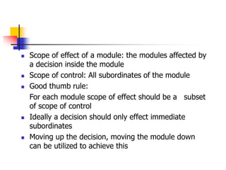
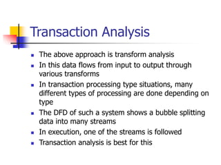
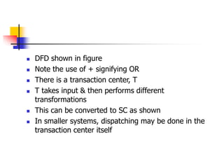
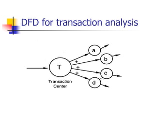
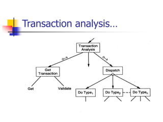
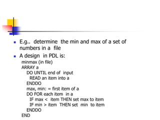
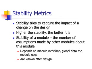
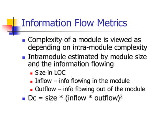
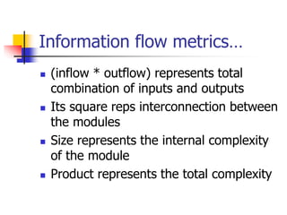
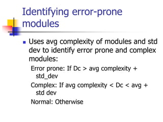
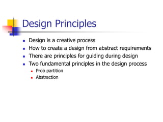
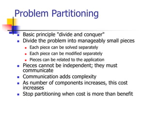
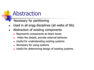
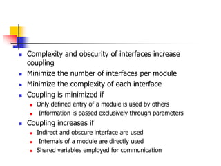
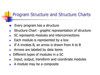
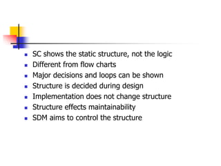
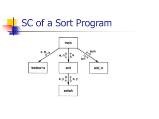
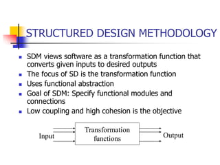
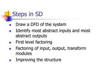
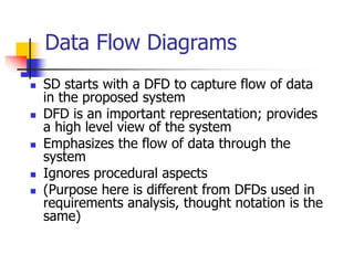
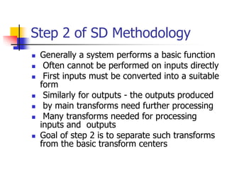
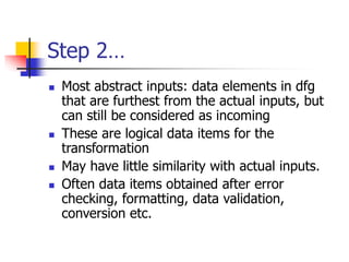
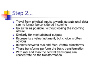
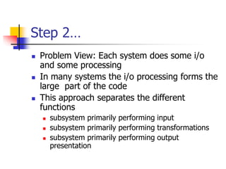
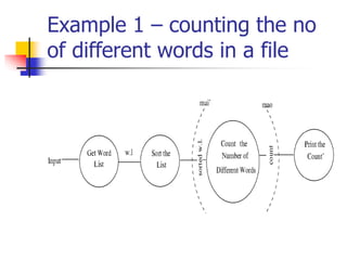
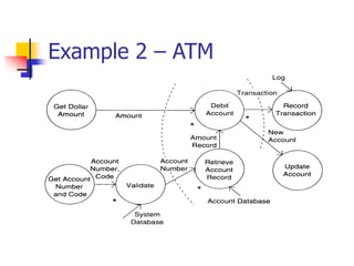
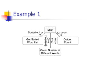
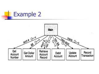
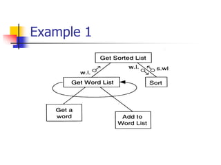
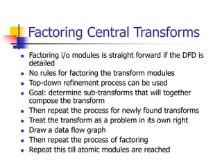
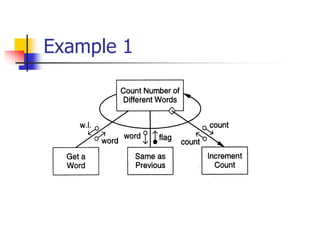
The document discusses structured design methodology. It begins by explaining program structure and structure charts, which graphically represent the structure of a program using boxes for modules and arrows for connections between modules. It then covers the steps in structured design, which include drawing a data flow diagram to capture system data flows, identifying the most abstract inputs and outputs, and performing first level factoring to break the system into input, output, and transform modules based on the data flow diagram. The goal is to specify functional modules and connections that result in low coupling and high cohesion.

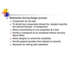
![Design Heuristics
The above steps should not be followed blindly
The structure obtained should be modified if needed
Low coupling, high cohesion being the goal
Design heuristics used to modify the initial design
Design heuristics - A set of thumb rules that are generally
useful
Module Size: Indication of module complexity Carefully
examine modules less than a few lines or greater than about
100 lines
Fan out and fan in [Fan-in refers to the number of higher-
level modules that directly call the module, while fan-out
refers to the number of lower-level modules directly called by
the module.]
A high fan out is not desired, should not be increased
beyond 5 or 6
Fan in should be maximized](https://image.slidesharecdn.com/68-design-230228051313-a87d5c17/85/6-8-Design-ppt-58-320.jpg)