1) The document describes a study investigating the effects of variable intake plenum length on the performance of a spark-ignition engine with electronically controlled fuel injectors.
2) Engine tests were conducted with additional plenum lengths of 16mm, 32mm, 48mm, and 64mm added to the original intake manifold.
3) The results showed that a 32mm plenum extension improved engine thermal efficiency, especially at lower engine speeds up to 3000rpm, while also reducing fuel consumption at high loads and low speeds.
![Design of a new SI engine intake manifold with variable length plenum
M.A. Ceviz *, M. Akın
Department of Mechanical Engineering, Faculty of Engineering, University of Atatürk, Erzurum 25240, Turkey
a r t i c l e i n f o
Article history:
Received 5 August 2009
Accepted 21 March 2010
Keywords:
Intake manifold
Intake plenum
Engine performance
a b s t r a c t
This paper investigates the effects of intake plenum length/volume on the performance characteristics of
a spark-ignited engine with electronically controlled fuel injectors. Previous work was carried out mainly
on the engine with carburetor producing a mixture desirable for combustion and dispatching the mixture
to the intake manifold. The more stringent emission legislations have driven engine development
towards concepts based on electronic-controlled fuel injection rather than the use of carburetors. In
the engine with multipoint fuel injection system using electronically controlled fuel injectors has an
intake manifold in which only the air flows and, the fuel is injected onto the intake valve. Since the intake
manifolds transport mainly air, the supercharging effects of the variable length intake plenum will be dif-
ferent from carbureted engine.
Engine tests have been carried out with the aim of constituting a base study to design a new variable
length intake manifold plenum. Engine performance characteristics such as brake torque, brake power,
thermal efficiency and specific fuel consumption were taken into consideration to evaluate the effects
of the variation in the length of intake plenum. The results showed that the variation in the plenum
length causes an improvement on the engine performance characteristics especially on the fuel consump-
tion at high load and low engine speeds which are put forward the system using for urban roads. Accord-
ing to the test results, plenum length must be extended for low engine speeds and shortened as the
engine speed increases. A system taking into account the results of the study was developed to adjust
the intake plenum length.
Ó 2010 Elsevier Ltd. All rights reserved.
1. Introduction
It is known that the design of engine components, measuring
and control methodology of the operating parameters are very
important to improve the engine performance and emission char-
acteristics. Effectively adjusting the operating parameters such as
the relative air–fuel ratio, spark timing, fuel injection timing, valve
timing, exhaust gas recirculation ratio and compression ratio in SI
and CI engines at different engine operation conditions improves
significantly the engine characteristics. The effects of such engine
operating parameters and their control technologies have been
studied excessively by researchers and the product designers. In
engines, configuration of the intake system plays also an important
role on the engine performance, and there are many experimental
and theoretical studies on the intake system and manifold design
[1–6].
Intake manifolds consist typically of a plenum, to the inlet of
which bolts the throttle-body, with the individual runners feeding
branches which lead to each cylinder. Important design criteria
are: low air flow resistance; good distribution of air and fuel be-
tween cylinders; runner and branch lengths that take advantage
of ram and tuning effects; sufficient (but not excessive) heating
to ensure adequate fuel vaporization with carbureted or throttle-
body injected engines [7]. The intake system on an engine has
one main goal, to get as much air–fuel mixture into the cylinder
as possible.
The intermittent or pulsating nature of the airflow through the
intake manifold into each cylinder may develop resonances in the
airflow at certain speeds. These may increase the engine perfor-
mance characteristics at certain engine speeds, but may reduce
at other speeds, depending on manifold dimensions and shape.
Conventional intake manifolds for vehicles have fixed air flow
geometry and static intake manifold. With a static intake manifold,
the speed at which intake tuning occurs is fixed. A static intake
manifold can only be optimized for one specific rpm, so it is bene-
ficial to develop a method to vary the intake length/volume, since
the engine operates over a broad speed range.
Variable length intake manifold technology uses the pressure
variations generated by the pulsating flow due to the periodic pis-
ton and valve motion to produce a charging effect. Various designs
for variable intake geometry have met with varying degrees of suc-
cess. The designs of the variable intake manifolds may be rather
0196-8904/$ - see front matter Ó 2010 Elsevier Ltd. All rights reserved.
doi:10.1016/j.enconman.2010.03.018
* Corresponding author. Fax: +90 442 236 09 57.
E-mail address: aceviz@atauni.edu.tr (M.A. Ceviz).
Energy Conversion and Management 51 (2010) 2239–2244
Contents lists available at ScienceDirect
Energy Conversion and Management
journal homepage: www.elsevier.com/locate/enconman](https://image.slidesharecdn.com/design-of-intake-manifold-150924095930-lva1-app6891/75/Design-of-intake-manifold-1-2048.jpg)
![complex and expensive to produce. Difficulty in servicing and a
limited range of variable tuning may also be disadvantageous de-
sign results of variable intake manifolds. Studies on the intake
manifold design by regulating the runner length/volume for higher
engine performance, optimal fuel consumption and lower emis-
sions have significantly increased in the last years. Some of the
studies carried out by researchers and engine manufacturers (i.e.
Mazda, BMW, Audi) [8–11] change the intake runner length; how-
ever, it is known that intake plenum affects seriously the charging
conditions [12–14].
Previous work [12] on the effects of intake plenum on some en-
gine performance characteristics was carried out mainly on the
carbureted engine. The carburetor produces the fuel and air mix-
ture needed for the operation of the engine and is coupled to the
intake manifold which receives the mixture and distributes it to
the cylinders. Design of intake plenum is active on the quality of
air–fuel mixture homogeneity in carbureted engine. In the engine
with multipoint injection systems using electronically controlled
fuel injectors has an intake manifold in which only the air flows.
The fuel is injected directly into the intake ports and the system
delivers a more evenly distributed mixture of air and fuel to each
of the engine’s cylinders, which improves power and performance.
Engines with multipoint injection have a separate fuel injector lo-
cated to each cylinder intake port. Such injection systems are ideal
for complying with the demands made on the air and fuel mixture
formation system.
In this paper, the effects of intake plenum length/volume varia-
tion on the engine performance were studied experimentally on a
spark-ignited engine with multipoint injection systems using elec-
tronically controlled fuel injectors. The results were used for the
design studies of variable length/volume intake plenum. A new
plenum length control system was produced and explained in
detail.
2. Materials and methods
A schematic layout of the test setup used is indicated in Fig. 1.
The engine test bed was explained in the previous studies of the
author [12,15,16], which consists of a control panel, a hydraulic
dynamometer and measurement instruments. The engine specifi-
cation is summarized in Table 1.
The engine performance characteristics through the various
points were calculated as follows: the brake power (Pb) delivered
by the engine and absorbed by the dynamometer is,
Pb ¼ 2pnT10À3
ð1Þ
where n is the crankshaft rotational speed (rev sÀ1
) and T is the tor-
que (Nm).
The thermal efficiency of the engine is,
gth ¼
Pb
Q
ð2Þ
Q is the total heat supplied by the fuel was calculated from,
Q ¼ CV _mf ð3Þ
where _mf is the fuel consumption (kg snÀ1
) and CV is the lower cal-
orific value of the fuel (kJ kgÀ1
).
The specific fuel consumption (sfc) is the fuel flow rate per unit
power output and calculated from,
sfc ¼
_mf
Pb
ð4Þ
where _mf is the fuel consumption (g hÀ1
) and Pb is the brake power
(kW).
At the beginning of experiments, the engine was run at a near
three-quarter opening position of the throttle valve in order to at-
tain near maximum speed. After the engine reached the steady-
state conditions, the first experiment was conducted with original
intake manifold. The engine was gradually loaded by the hydraulic
dynamometer and test matrix consisted of eight speeds ranging
from 1500 to 5000 rpm with 500 rpm steps for each plenum addi-
tion operation. The experiments were repeated with separately
16 mm (40 cm3
), 32 mm (80 cm3
), 48 mm (120 cm3
) and 64 mm
(160 cm3
) plenum addition at the same engine speeds that were
attained by loading hydraulic dynamometer. The additional ple-
nums had the geometries suitable for entrance of the original in-
take manifold, and located among the throttle valve and intake
manifold plenum.
3. Results and discussion
Figs. 2–5 show the effect of the plenum length on the engine
performance characteristics; thermal efficiency, specific fuel con-
sumption, torque and brake power, respectively. It can be seen
from Fig. 2 that the highest engine thermal efficiency is observed
1- Engine 7- Air flow meter
2- Hydraulic dynamometer 8- Muffler
3- Gravimetric fuel flow meter 9- Exhaust gas analyzer
4- Additional plenums 10- Distributor
5- Air surge tank 11- Fuel Injectors
6- Air flow meter probe (hot wire)
3
6
7
10
1
2
5
9
4
8
11
Fig. 1. A schematic layout of test setup.
Table 1
Engine specifications.
Engine type Ford MVH-418, fuel injected
Number of cylinders 4
Compression ratio 10:1
Bore (mm) 80.6
Stroke (mm) 88
Displacement volume (dm3
) 1.796
Maximum power 93 kW at 6250 rpm
Maximum torque 157 Nm at 4500 rpm
Cooling system Water-cooled
2240 M.A. Ceviz, M. Akın / Energy Conversion and Management 51 (2010) 2239–2244](https://image.slidesharecdn.com/design-of-intake-manifold-150924095930-lva1-app6891/75/Design-of-intake-manifold-2-2048.jpg)
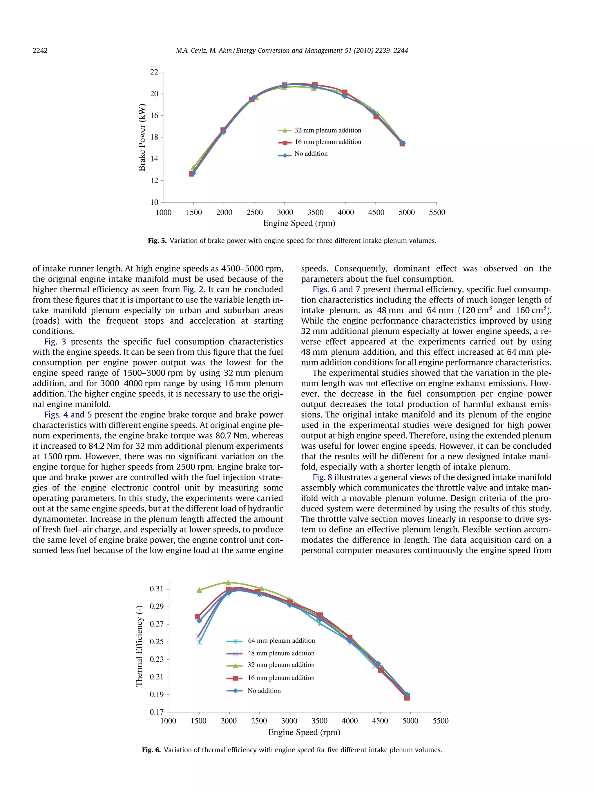
![at 32 mm plenum addition up to 3000 rpm. Improvement in the
engine thermal efficiency was especially at lower engine speeds.
At the experiments with the original engine manifold, engine ther-
mal efficiency was 27.4%, whereas it increased to 27.9% and 30.9%
for 16 mm and 32 mm plenum addition at 1500 rpm, respectively.
There was also an increase in the engine thermal efficiency at
the experiments carried out by 16 mm plenum addition up to
3000 rpm.
The highest engine thermal efficiency was attained by using
16 mm plenum addition at about the engine speed range of
3000–4000 rpm. As the engine speed increases, the higher engine
thermal efficiency was attained at lower length of intake plenum.
It is necessary to shorten of intake manifold length as the engine
speed increases because of the increase in the flow frequency as
discussed in introduction section. The results of this study agreed
well with early studies [8–11,17], which were about the effects
0.17
0.19
0.21
0.23
0.25
0.27
0.29
0.31
1000 1500 2000 2500 3000 3500 4000 4500 5000 5500
ThermalEfficiency(-)
Engine Speed (rpm)
No addition
16 mm plenum addition
32 mm plenum addition
Fig. 2. Variation of thermal efficiency with engine speed for three different intake plenum volumes.
250
300
350
400
450
500
1000 1500 2000 2500 3000 3500 4000 4500 5000 5500
SpecificFuelConsumption(g/kW.h)
Engine Speed (rpm)
No addition
16 mm plenum addition
32 mm plenum addition
Fig. 3. Variation of specific fuel consumption with engine speed for three different intake plenum volumes.
20
30
40
50
60
70
80
90
1000 1500 2000 2500 3000 3500 4000 4500 5000 5500
BrakeTorque(N.m)
Engine Speed (rpm)
No addition
16 mm plenum addition
32 mm plenum addition
Fig. 4. Variation of brake torque with engine speed for three different intake plenum volumes.
M.A. Ceviz, M. Akın / Energy Conversion and Management 51 (2010) 2239–2244 2241](https://image.slidesharecdn.com/design-of-intake-manifold-150924095930-lva1-app6891/75/Design-of-intake-manifold-3-2048.jpg)
![engine shaft encoder. The drive system actuates the throttle valve
section based on the engine speed information from data acquisi-
tion card. In operation at low speeds, the throttle valve section is
driven to extend the flexible section to increase the length between
plenum and throttle valve. As the engine speed increases, the
throttle valve is driven to shorten the flexible section. The system
therefore provides a cost effective variable intake manifold plenum
which will operate with different types of engines.
4. Conclusions
From the results of this study, the following conclusions can be
deduced:
1. The intake manifold plenum length/volume is highly effective
on engine performance characteristics especially with the fuel
consumption parameters for SI engines with multipoint fuel
injection system. The engine performance can be improved by
using continuously variable intake plenum length.
2. Favorable effects of the variable length intake manifold plenum
appeared at high load and low engine speeds. Therefore, vari-
able length intake manifold plenum is useful especially on
urban and suburban areas (roads) with the frequent stops and
acceleration at starting conditions.
3. It is necessary to determine the length of additional plenum
components for another engine and intake system with sensi-
tive experimental studies.
Acknowledgement
This work has been supported by The Scientific and Technolog-
ical Research Council of Turkey (TUBITAK, Project No. 107M018).
References
[1] Benajes J, Reyes E, Galindo J, Peidro J. Predesign model for intake manifolds in
internal combustion engines. SAE Paper No: 970055; 1997.
[2] Safari M, Ghamari M, Nasiritosi A. Intake manifold optimization by using 3-D
CFD analysis. SAE Paper No: 2003-32-0073; 2003.
[3] Sung NW, Choi JS, Jeong YI. A study on the flow in the engine intake system.
SAE Paper No: 952067; 1995.
[4] Tsukakoshi S, Miya H, Miyake M. Development of a plastic intake manifold.
SAE Paper No: 930085; 1993.
[5] Jawad BA, Hoste JP, Johnson BE. Intake system design for a formula SAE
application. SAE Paper No: 2001-01-2553; 2001.
[6] Jawad BA, Dragoiu A, Dyar L, Zellner K, Riedel C. Intake design for maximum
performance. SAE Paper No: 2003-01-2277; 2003.
[7] Heywood JB. Internal combustion engine fundamentals. McGraw-Hill Inc.;
1988.
[8] Krömer G, Pölzl HW, Thude M, Leitner P. The new Audi V6 engine. SAE Paper
No: 910678; 1991.
[9] Narayanaswamy K. Continuously variable intake manifold with intelligent
position control. US Patent No: 6983,727; 2006.
250
300
350
400
450
500
1000 1500 2000 2500 3000 3500 4000 4500 5000 5500
SpecificFuelConsumption(g/kW.h)
Engine Speed (rpm)
No addition
16 mm plenum addition
32 mm plenum addition
48 mm plenum addition
64 mm plenum addition
Fig. 7. Variation of specific fuel consumption with engine speed for five different intake plenum volumes.
Runner
Engine
Plenum
Flexible
section
Throttle valve
Drive
module
A
Drive
module
Throttle valve
Engine
Plenum
Runner
Runner
Flexible section
Engine
B
C
Fig. 8. (A) Front, (B) top and (C) solid view of intake manifold assembly.
M.A. Ceviz, M. Akın / Energy Conversion and Management 51 (2010) 2239–2244 2243](https://image.slidesharecdn.com/design-of-intake-manifold-150924095930-lva1-app6891/75/Design-of-intake-manifold-5-2048.jpg)
![[10] Verkleeren RL. Split plenum manifold with variable runners. US Patent No:
5762,036; 1998.
[11] Moroto K. Variable intake air apparatus. US Patent No: 5740,770; 1998.
[12] Ceviz MA. Intake plenum volume and its influence on the engine performance,
cyclic variability and emissions. Energy Convers Manage 2007;48:961–6.
[13] Brady JM. A simple high-efficiency S.I. engine design. SAE Paper No: 2003-01-
0923; 2003.
[14] Kondapalli PS. General guidelines for improving burst pressure strength of
welded nylon air intake manifolds. SAE Paper No 2000-01-0040; 2000.
[15] Ceviz MA, Yüksel F. Effects of ethanol-unleaded gasoline blends on cyclic
variability and emissions in an SI engine. Appl Therm Eng 2005;25(5–
6):917–25.
[16] Ceviz MA, Kaymaz _I. Temperature and air–fuel ratio dependent specific heat
ratio functions for lean burned and unburned mixture. Energy Convers
Manage 2005;46:2387–404.
[17] Vitek O, Polaesk M. Tuned manifold systems-application of 1-D pipe model.
SAE Paper No: 2002-01-0004; 2002.
2244 M.A. Ceviz, M. Akın / Energy Conversion and Management 51 (2010) 2239–2244](https://image.slidesharecdn.com/design-of-intake-manifold-150924095930-lva1-app6891/75/Design-of-intake-manifold-6-2048.jpg)