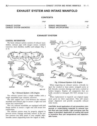
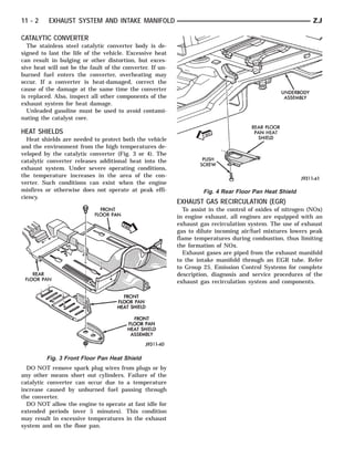
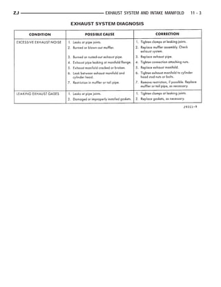
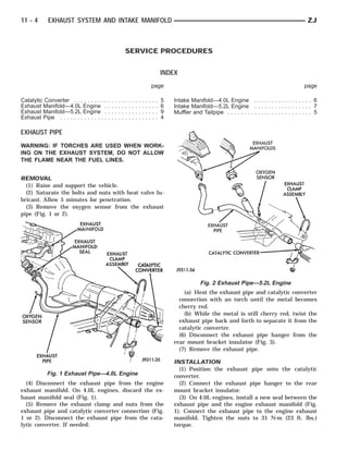
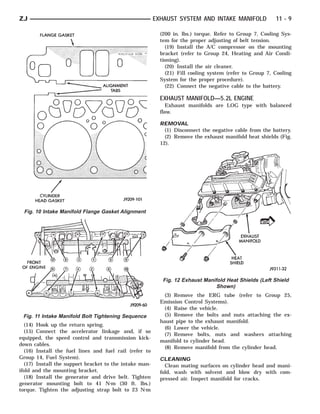
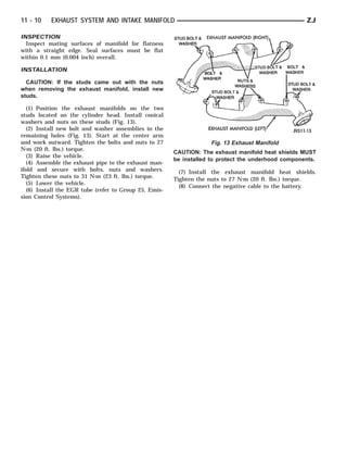
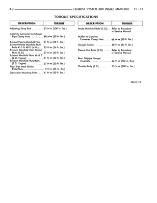
This document provides information about exhaust systems and intake manifolds. It discusses the basic components of exhaust systems, including exhaust manifolds, pipes, catalytic converters, heat shields, mufflers and tailpipes. It describes symptoms of exhaust system problems and provides procedures for removing and installing exhaust pipes and manifolds. Intake manifolds and catalytic converters are also discussed.
Manual de servicio del motor isuzu nos permite probar, diagnosticar para dar servicio de mantenimiento preventivo, correctivo de acuerdo a los datos del fabricante a fin de que el motor opere de acuerdo a los estándares reduciendo la contaminación ambiental, se vera el ajuste de las válvulas o calibración de acuerdo al manual del fabricante. para que opere correctamente.
KomatsuIndia is the largest manufacturer & supplier of rigid dump truck in India. Find out some more high performance rigid dump truck like HD465-7E0, HD785-7, HD1500-7, 730E, 830E-1AC, 860E-1K, 930E-4, 930E-4SE & 930E-2K from around the India. For more info click here : http://www.komatsuindia.in/rigid_dump_trucks.php
Comparison in the Fuel System between Caterpillar Engines
3408C and C18 ACERT™
About Engines
Engine Numbering System
- Cat® 3408C Engine
- Cat® C18 Engine
Fuel System
- Cat® 3408C Engine
- Cat® C18 Engine
Steam Turbine Lube Oil System Protections Using SCADA & PLCNilesh Jha
Steam Turbine Protection System is designed with today technology to operate the thermal power plants in safe and reliable manner. The protection system operates only when any of the control system set point parameter is exceeded, and the steam turbine will damaged if it continues to operate. This paper presents overview of the steam turbine protection logics of lube of system and implementation for smooth automatic operation by using SIMATIC S7 PLC programming along with monitoring SCADA SYSTEM by using WinCC software.
Demand for high quality, greater efficiency and an automated machine has increased day by day in the industrial sector as well as power plants [1]. Power plants require continuous monitoring and inspection at frequent intervals. There are possibilities of errors at measuring and various stages involved with human workers and also the lack of few features of microcontrollers. Thus this paper takes a sincere attempt to explain the advantages that will be obtained by implementing automation system. The turbine lube oil system control which is the most important part of any power plant, and its automation is the precise effort of this paper. In order to automate a power plant and minimize human intervention, there is a need to develop PLC based system along with monitoring SCADA system that monitors the plant and helps reduce the errors caused by humans [2]. The internal storage of instruction of PLC is used for implementing function to control various types of machines and processes through digital or analog input/output modules. PLC systems are used to monitor and control a plant or equipment in industries such as power plants, energy, oil and gas refining and transportation.
This is the Highly Detailed factory service repair manual for the1999 TOYOTA COROLLA, this Service Manual has detailed illustrations as well as step by step instructions,It is 100 percents complete and intact. they are specifically written for the do-it-yourself-er as well as the experienced mechanic.1999 TOYOTA COROLLA Service Repair Workshop Manual provides step-by-step instructions based on the complete dis-assembly of the machine. It is this level of detail, along with hundreds of photos and illustrations, that guide the reader through each service and repair procedure. Complete download comes in pdf format which can work under all PC based windows operating system and Mac also, All pages are printable. Using this repair manual is an inexpensive way to keep your vehicle working properly.
Service Repair Manual Covers:
Maintenance
Engine
Control System
Mechanical
Fuel Service Specifications
Emission Control
Intake Exhaust Cooling
Lube
Ignition Starting Charging
Auto Transmission Clutch
Manual Transmission
Transfer Propeller Shaft
Drive Shaft
Differential
Axle Suspension
Tire & Wheel
Brake Control
Brake
Parking Brake
Steering Column
Power Steering
Air Condition
Suppl Restraint System
Seat Belt
Engine Immobilizer
Cruise Control
Wiper & Washer
Door Lock
Meter Audio/Visual
Horn
Windshield/Glass Mirror
Instrument Panel
Seat
Engine Hood/ Door
Exterior & Interior
Electrical
Multiplex/ Can Communication
And much more
File Format: PDF
Compatible: All Versions of Windows & Mac
Language: English
Requirements: Adobe PDF Reader
NO waiting, Buy from responsible seller and get INSTANT DOWNLOAD, Without wasting your hard-owned money on uncertainty or surprise! All pages are is great to have1999 TOYOTA COROLLA Service Repair Workshop Manual.
Looking for some other Service Repair Manual,please check:
https://www.aservicemanualpdf.com/
Thanks for visiting!
8
Zenith Tecnica produces EBMAM Titanium exhaust manifold for Freevalve ABJonathan Paul
Proudly built by the team at Zenith Tecnica with EBM technology.
Pushing additive manufacturing boundaries further with this titanium exhaust manifold for Freevalve AB's prototype 1.6L camless engine.
Built and delivered to the customer within 7 days. At half the weight of Inconel, the titanium manifold has successfully been tested for greater than 150 hours at over 900°C.
What Are The Immediate Steps To Take When The VW Temperature Light Starts Fla...Import Motorworks
Learn how to respond when the red temperature light flashes in your VW with this presentation. From checking coolant levels to seeking professional help, follow these steps promptly to prevent engine damage and ensure safety on the road.
5 Warning Signs Your BMW's Intelligent Battery Sensor Needs AttentionBertini's German Motors
IBS monitors and manages your BMW’s battery performance. If it malfunctions, you will have to deal with an array of electrical issues in your vehicle. Recognize warning signs like dimming headlights, frequent battery replacements, and electrical malfunctions to address potential IBS issues promptly.
Comprehensive program for Agricultural Finance, the Automotive Sector, and Empowerment . We will define the full scope and provide a detailed two-week plan for identifying strategic partners in each area within Limpopo, including target areas.:
1. Agricultural : Supporting Primary and Secondary Agriculture
• Scope: Provide support solutions to enhance agricultural productivity and sustainability.
• Target Areas: Polokwane, Tzaneen, Thohoyandou, Makhado, and Giyani.
2. Automotive Sector: Partnerships with Mechanics and Panel Beater Shops
• Scope: Develop collaborations with automotive service providers to improve service quality and business operations.
• Target Areas: Polokwane, Lephalale, Mokopane, Phalaborwa, and Bela-Bela.
3. Empowerment : Focusing on Women Empowerment
• Scope: Provide business support support and training to women-owned businesses, promoting economic inclusion.
• Target Areas: Polokwane, Thohoyandou, Musina, Burgersfort, and Louis Trichardt.
We will also prioritize Industrial Economic Zone areas and their priorities.
Sign up on https://profilesmes.online/welcome/
To be eligible:
1. You must have a registered business and operate in Limpopo
2. Generate revenue
3. Sectors : Agriculture ( primary and secondary) and Automative
Women and Youth are encouraged to apply even if you don't fall in those sectors.
Your VW's camshaft position sensor is crucial for engine performance. Signs of failure include engine misfires, difficulty starting, stalling at low speeds, reduced fuel efficiency, and the check engine light. Prompt inspection and replacement can prevent further damage and keep your VW running smoothly.
Why Is Your BMW X3 Hood Not Responding To Release CommandsDart Auto
Experiencing difficulty opening your BMW X3's hood? This guide explores potential issues like mechanical obstruction, hood release mechanism failure, electrical problems, and emergency release malfunctions. Troubleshooting tips include basic checks, clearing obstructions, applying pressure, and using the emergency release.
The Octavia range embodies the design trend of the Škoda brand: a fusion of
aesthetics, safety and practicality. Whether you see the car as a whole or step
closer and explore its unique features, the Octavia range radiates with the
harmony of functionality and emotion
In this presentation, we have discussed a very important feature of BMW X5 cars… the Comfort Access. Things that can significantly limit its functionality. And things that you can try to restore the functionality of such a convenient feature of your vehicle.
Ever been troubled by the blinking sign and didn’t know what to do?
Here’s a handy guide to dashboard symbols so that you’ll never be confused again!
Save them for later and save the trouble!
𝘼𝙣𝙩𝙞𝙦𝙪𝙚 𝙋𝙡𝙖𝙨𝙩𝙞𝙘 𝙏𝙧𝙖𝙙𝙚𝙧𝙨 𝙞𝙨 𝙫𝙚𝙧𝙮 𝙛𝙖𝙢𝙤𝙪𝙨 𝙛𝙤𝙧 𝙢𝙖𝙣𝙪𝙛𝙖𝙘𝙩𝙪𝙧𝙞𝙣𝙜 𝙩𝙝𝙚𝙞𝙧 𝙥𝙧𝙤𝙙𝙪𝙘𝙩𝙨. 𝙒𝙚 𝙝𝙖𝙫𝙚 𝙖𝙡𝙡 𝙩𝙝𝙚 𝙥𝙡𝙖𝙨𝙩𝙞𝙘 𝙜𝙧𝙖𝙣𝙪𝙡𝙚𝙨 𝙪𝙨𝙚𝙙 𝙞𝙣 𝙖𝙪𝙩𝙤𝙢𝙤𝙩𝙞𝙫𝙚 𝙖𝙣𝙙 𝙖𝙪𝙩𝙤 𝙥𝙖𝙧𝙩𝙨 𝙖𝙣𝙙 𝙖𝙡𝙡 𝙩𝙝𝙚 𝙛𝙖𝙢𝙤𝙪𝙨 𝙘𝙤𝙢𝙥𝙖𝙣𝙞𝙚𝙨 𝙗𝙪𝙮 𝙩𝙝𝙚 𝙜𝙧𝙖𝙣𝙪𝙡𝙚𝙨 𝙛𝙧𝙤𝙢 𝙪𝙨.
Over the 10 years, we have gained a strong foothold in the market due to our range's high quality, competitive prices, and time-lined delivery schedules.
Things to remember while upgrading the brakes of your carjennifermiller8137
Upgrading the brakes of your car? Keep these things in mind before doing so. Additionally, start using an OBD 2 GPS tracker so that you never miss a vehicle maintenance appointment. On top of this, a car GPS tracker will also let you master good driving habits that will let you increase the operational life of your car’s brakes.
What Does the PARKTRONIC Inoperative, See Owner's Manual Message Mean for You...Autohaus Service and Sales
Learn what "PARKTRONIC Inoperative, See Owner's Manual" means for your Mercedes-Benz. This message indicates a malfunction in the parking assistance system, potentially due to sensor issues or electrical faults. Prompt attention is crucial to ensure safety and functionality. Follow steps outlined for diagnosis and repair in the owner's manual.
Symptoms like intermittent starting and key recognition errors signal potential problems with your Mercedes’ EIS. Use diagnostic steps like error code checks and spare key tests. Professional diagnosis and solutions like EIS replacement ensure safe driving. Consult a qualified technician for accurate diagnosis and repair.
Wondering if Your Mercedes EIS is at Fault Here’s How to Tell
95ZJ_11.PDF
1. ZJ EXHAUST SYSTEM AND INTAKE MANIFOLD 11 - 1
EXHAUST SYSTEM AND INTAKE MANIFOLD
CONTENTS
page page
EXHAUST SYSTEM . . . . . . . . . . . . . . . . . . . . . . . 1 SERVICE PROCEDURES . . . . . . . . . . . . . . . . . . . 4
EXHAUST SYSTEM DIAGNOSIS . . . . . . . . . . . . . 3 TORQUE SPECIFICATIONS . . . . . . . . . . . . . . . . 11
EXHAUST SYSTEM
GENERAL INFORMATION
The basic exhaust system consists of exhaust man-
ifold(s), exhaust pipe with oxygen sensor, catalytic
converter, heat shield(s), muffler and tailpipe (Fig. 1
or 2).
Fig. 2 Exhaust System—5.2L Engine
When inspecting an exhaust system, critically in-
spect for cracked or loose joints, stripped screw or
bolt threads, corrosion damage and worn, cracked or
broken hangers. Replace all components that are
Fig. 1 Exhaust System—4.0L Engine badly corroded or damaged. DO NOT attempt to re-
The exhaust system uses a single muffler with a pair.
single monolithic-type catalytic converter. When replacement is required, use original equip-
The 4.0L engines use a seal between the exhaust ment parts (or their equivalent). This will assure
manifold and exhaust pipe to assure a tight seal and proper alignment and provide acceptable exhaust
strain free connections. noise levels.
The 5.2L exhaust manifolds are equipped with ball
CAUTION: Avoid application of rust prevention com-
flange outlets to assure a tight seal and strain free
pounds or undercoating materials to exhaust sys-
connections.
tem floor pan heat shields. Light overspray near the
The exhaust system must be properly aligned to
edges is permitted. Application of coating will result
prevent stress, leakage and body contact. If the sys-
in excessive floor pan temperatures and objection-
tem contacts any body panel, it may amplify objec-
able fumes.
tionable noises originating from the engine or body.
2. 11 - 2 EXHAUST SYSTEM AND INTAKE MANIFOLD ZJ
CATALYTIC CONVERTER
The stainless steel catalytic converter body is de-
signed to last the life of the vehicle. Excessive heat
can result in bulging or other distortion, but exces-
sive heat will not be the fault of the converter. If un-
burned fuel enters the converter, overheating may
occur. If a converter is heat-damaged, correct the
cause of the damage at the same time the converter
is replaced. Also, inspect all other components of the
exhaust system for heat damage.
Unleaded gasoline must be used to avoid contami-
nating the catalyst core.
HEAT SHIELDS
Heat shields are needed to protect both the vehicle
and the environment from the high temperatures de-
veloped by the catalytic converter (Fig. 3 or 4). The
catalytic converter releases additional heat into the
exhaust system. Under severe operating conditions,
the temperature increases in the area of the con-
verter. Such conditions can exist when the engine
misfires or otherwise does not operate at peak effi- Fig. 4 Rear Floor Pan Heat Shield
ciency.
EXHAUST GAS RECIRCULATION (EGR)
To assist in the control of oxides of nitrogen (NOx)
in engine exhaust, all engines are equipped with an
exhaust gas recirculation system. The use of exhaust
gas to dilute incoming air/fuel mixtures lowers peak
flame temperatures during combustion, thus limiting
the formation of NOx.
Exhaust gases are piped from the exhaust manifold
to the intake manifold through an EGR tube. Refer
to Group 25, Emission Control Systems for complete
description, diagnosis and service procedures of the
exhaust gas recirculation system and components.
Fig. 3 Front Floor Pan Heat Shield
DO NOT remove spark plug wires from plugs or by
any other means short out cylinders. Failure of the
catalytic converter can occur due to a temperature
increase caused by unburned fuel passing through
the converter.
DO NOT allow the engine to operate at fast idle for
extended periods (over 5 minutes). This condition
may result in excessive temperatures in the exhaust
system and on the floor pan.
3. ZJ EXHAUST SYSTEM AND INTAKE MANIFOLD 11 - 3
EXHAUST SYSTEM DIAGNOSIS
4. 11 - 4 EXHAUST SYSTEM AND INTAKE MANIFOLD ZJ
SERVICE PROCEDURES
INDEX
page page
Catalytic Converter . . . . . . . . . . . . . . . . . . . . . . . . . 5 Intake Manifold—4.0L Engine . . . . . . . . . . . . . . . . . 6
Exhaust Manifold—4.0L Engine . . . . . . . . . . . . . . . . 6 Intake Manifold—5.2L Engine . . . . . . . . . . . . . . . . . 7
Exhaust Manifold—5.2L Engine . . . . . . . . . . . . . . . . 9 Muffler and Tailpipe . . . . . . . . . . . . . . . . . . . . . . . . . 5
Exhaust Pipe . . . . . . . . . . . . . . . . . . . . . . . . . . . . . 4
EXHAUST PIPE
WARNING: IF TORCHES ARE USED WHEN WORK-
ING ON THE EXHAUST SYSTEM, DO NOT ALLOW
THE FLAME NEAR THE FUEL LINES.
REMOVAL
(1) Raise and support the vehicle.
(2) Saturate the bolts and nuts with heat valve lu-
bricant. Allow 5 minutes for penetration.
(3) Remove the oxygen sensor from the exhaust
pipe (Fig. 1 or 2).
Fig. 2 Exhaust Pipe—5.2L Engine
(a) Heat the exhaust pipe and catalytic converter
connection with an torch until the metal becomes
cherry red.
(b) While the metal is still cherry red, twist the
exhaust pipe back and forth to separate it from the
catalytic converter.
(6) Disconnect the exhaust pipe hanger from the
rear mount bracket insulator (Fig. 3).
(7) Remove the exhaust pipe.
INSTALLATION
(1) Position the exhaust pipe onto the catalytic
Fig. 1 Exhaust Pipe—4.0L Engine converter.
(4) Disconnect the exhaust pipe from the engine (2) Connect the exhaust pipe hanger to the rear
exhaust manifold. On 4.0L engines, discard the ex- mount bracket insulator.
haust manifold seal (Fig. 1). (3) On 4.0L engines, install a new seal between the
(5) Remove the exhaust clamp and nuts from the exhaust pipe and the engine exhaust manifold (Fig.
exhaust pipe and catalytic converter connection (Fig. 1). Connect the exhaust pipe to the engine exhaust
1 or 2). Disconnect the exhaust pipe from the cata- manifold. Tighten the nuts to 31 N⅐m (23 ft. lbs.)
lytic converter. If needed: torque.
5. ZJ EXHAUST SYSTEM AND INTAKE MANIFOLD 11 - 5
Fig. 3 Rear Mount Bracket Insulator
(4) Position the exhaust clamp assembly over the
exhaust pipe/catalytic converter connection (Fig. 1 or Fig. 4 Exhaust Pipe-to-Catalytic Converter-to-Muffler
2). Tighten the nuts to 68 N⅐m (50 ft. lbs.) torque. Connection
(5) Coat the oxygen sensor with anti-seize com- INSTALLATION
pound. Install the sensor and tighten the nut to 48 (1) Position the exhaust clamp assembly over the
N⅐m (35 ft. lbs.) torque. exhaust pipe/catalytic converter connection (Fig. 4).
(6) Lower the vehicle. Tighten the nuts to 68 N⅐m (50 ft. lbs.) torque.
(7) Start the engine and inspect for exhaust leaks (2) Install the muffler onto the catalytic converter
and exhaust system contact with the body panels. until the alignment tab is inserted into the align-
Adjust the alignment, if needed. ment slot.
(8) After initial start-up, check the engine exhaust (3) Install the exhaust clamp assembly at the muf-
manifold to exhaust pipe nuts for proper torque. fler and catalytic converter connection (Fig. 4).
Tighten the clamp nuts to 68 N⅐m (50 ft. lbs.) torque.
CATALYTIC CONVERTER (4) Lower the vehicle.
(5) Start the engine and inspect for exhaust leaks
WARNING: IF TORCHES ARE USED WHEN WORK-
and exhaust system contact with the body panels.
ING ON THE EXHAUST SYSTEM, DO NOT ALLOW
Adjust the alignment, if needed.
THE FLAME NEAR THE FUEL LINES.
MUFFLER AND TAILPIPE
REMOVAL All original equipment exhaust systems are manu-
(1) Raise and support the vehicle. factured with the tailpipe welded to the muffler. Ser-
(2) Saturate the bolts and nuts with heat valve lu- vice replacement mufflers and tailpipes are either
bricant. Allow 5 minutes for penetration. clamped together or welded together.
(3) Remove the clamp and nuts from the catalytic
converter and exhaust pipe connection (Fig. 4). WARNING: IF TORCHES ARE USED WHEN WORK-
(4) Remove the clamp and nuts from the catalytic ING ON THE EXHAUST SYSTEM, DO NOT ALLOW
converter and muffler connection (Fig. 4). THE FLAME NEAR THE FUEL LINES.
(5) Heat the exhaust pipe, catalytic converter and
muffler connections with an torch until the metal be- REMOVAL
comes cherry red. (1) Raise and support the vehicle.
(6) While the metal is still cherry red, twist the (2) Saturate the bolts and nuts with heat valve lu-
catalytic converter back and forth to separate it from bricant. Allow 5 minutes for penetration.
the exhaust pipe and the muffler. (3) Remove the exhaust clamp and nuts from the
catalytic converter and muffler connection (Fig. 4).
6. 11 - 6 EXHAUST SYSTEM AND INTAKE MANIFOLD ZJ
(4) Heat the catalytic converter-to-muffler connec- (3) Remove the air cleaner assembly.
tion with an torch until the metal becomes cherry (4) Remove the throttle cable, vehicle speed control
red. cable (if equipped) and the transmission line pres-
(5) While the metal is still cherry red, remove the sure cable.
tailpipe/muffler assembly from the catalytic con- (5) Disconnect all electrical connectors on the in-
verter. take manifold.
(6) Remove the tailpipe from the tailpipe hanger (6) Disconnect and remove the fuel system supply
(Fig. 5). and return lines from the fuel rail assembly (refer to
(7) Remove the tailpipe/muffler assembly. Group 14, Fuel System).
(7) Loosen the accessory drive belt (refer to Group
7, Cooling System). Loosen the tensioner.
(8) Remove the power steering pump and bracket
from the intake manifold and set aside.
(9) Remove the fuel rail and injectors (refer to
Group 14, Fuel System).
(10) Raise the vehicle.
(11) Disconnect the exhaust pipe from the engine
exhaust manifold. Discard the seal.
(12) Lower the vehicle.
(13) Remove the intake manifold and engine ex-
haust manifold.
CLEANING
Clean the mating surfaces of the cylinder head and
Fig. 5 Tailpipe Hanger the manifold if the original manifold is to be in-
INSTALLATION stalled.
(1) If the tailpipe hanger assembly was removed,
install the hanger to the frame. Tighten the bolts to INSTALLATION
22 N⅐m (192 in. lbs.) torque. If the manifold is being replaced, ensure all the fit-
(2) Position the tailpipe and muffler onto the ting, etc. are transferred to the replacement mani-
tailpipe hanger (Fig. 5). fold.
(3) Install the muffler onto the catalytic converter. (1) Install a new engine exhaust/intake manifold
Make sure that the tailpipe has sufficient clearance gasket over the alignment dowels on the cylinder
from the floor pan. Install the exhaust clamp assem- head.
bly and tighten the nuts to 68 N⅐m (50 ft. lbs.) (2) Position the engine exhaust manifold to the cyl-
torque. inder head. Install fastener No.3 and finger tighten
(4) Lower the vehicle. at this time (Fig. 6).
(5) Start the engine and inspect for exhaust leaks (3) Install intake manifold on the cylinder head
and exhaust system contact with the body panels. dowels.
Adjust the alignment, if needed. (4) Install washers and fasteners Nos.1, 2, 4, 5, 8,
9, 10 and 11 (Fig. 6).
EXHAUST MANIFOLD—4.0L ENGINE (5) Install washers and fasteners Nos.6 and 7 (Fig.
The intake and engine exhaust manifold must 6).
be removed and installed together. The mani- (6) Tighten the fasteners in sequence and to the
folds use a common gasket at the cylinder head. specified torque (Fig. 6).
Refer to Intake Manifold in this section for the • Fasteners Nos.1 through 5—Tighten to 33 N⅐m (24
proper removal and installation procedures. ft. lbs.) torque.
• Fasteners Nos.6 and 7—Tighten to 31 N⅐m (23 ft.
INTAKE MANIFOLD—4.0L ENGINE lbs.) torque.
The intake and engine exhaust manifold must • Fasteners Nos.8 through 11—Tighten to 33 N⅐m
be removed and installed together. The mani- (24 ft. lbs.) torque.
folds use a common gasket at the cylinder head. (7) Install the fuel rail and injectors (refer to
Group 14, Fuel System).
REMOVAL (8) Install the power steering pump and bracket to
(1) Disconnect the negative cable from the battery. the intake manifold. Tighten the belt to specification
(2) Remove air cleaner inlet hose from throttle (refer to Group 7, Cooling System for the proper pro-
plate assembly. cedures).
7. ZJ EXHAUST SYSTEM AND INTAKE MANIFOLD 11 - 7
(5) Remove the fuel lines and fuel rail (refer to
Group 14, Fuel System).
(6) Disconnect the accelerator linkage and, if so
equipped, the speed control and transmission kick-
down cables.
(7) Remove the return spring.
(8) Remove the distributor cap and wires.
(9) Disconnect the coil wires.
(10) Disconnect the heat indicator sending unit
wire.
(11) Disconnect the heater hoses and bypass hose.
(12) Remove the closed crankcase ventilation and
evaporation control systems.
(13) Remove the A/C compressor bolts and set the
compressor on the fan shroud.
Fig. 6 Engine Exhaust/Intake Manifold (14) Remove the support bracket from the intake
manifold and the mounting bracket.
(9) Install the fuel system supply and return lines (15) Remove intake manifold bolts.
to the fuel rail assembly. Before connecting the (16) Lift the intake manifold and throttle body out
fuel system lines to the fuel rail replace the O- of the engine compartment as an assembly.
rings in the quick-connect fuel line couplings. (17) Remove and discard the flange side gaskets
Refer to Group 14, Fuel System for the proper and the front and rear cross-over gaskets.
procedure. (18) Remove the throttle body bolts and lift the
(10) Connect all electrical connections on the in- throttle body off the intake manifold (Fig. 7). Discard
take manifold. the throttle body gasket.
(11) Connect the vacuum connector on the intake
manifold and install it in the bracket.
(12) Install throttle cable, vehicle speed control ca-
ble (if equipped).
(13) Install the transmission line pressure cable (if
equipped). Refer to Group 21, Transmission for the
adjustment procedures.
(14) Install air cleaner assembly.
(15) Connect air inlet hose to the throttle plate as-
sembly.
(16) Raise the vehicle on a side mounted hoist.
(17) Use a new engine exhaust manifold seal. Con-
nect the exhaust pipe to the engine exhaust mani-
fold.
(18) Lower the vehicle.
(19) Connect the negative cable to the battery.
(20) Start the engine and check for leaks. Fig. 7 Throttle Body Assembly
INTAKE MANIFOLD—5.2L ENGINE (19) Remove the plenum pan as follows:
The aluminum intake manifold is a single plane (a) Turn the intake manifold upside down. Sup-
design with equal length runners. The manifold is port the manifold.
sealed by flange side gaskets with front and rear (b) Remove the bolts and lift the pan off the
cross-over gaskets. The intake manifold has internal manifold. Discard the gasket.
EGR.
CLEANING
REMOVAL Clean manifold in solvent and blow dry with com-
(1) Disconnect the negative cable from the battery. pressed air.
(2) Drain the cooling system (refer to Group 7, Clean cylinder block front and rear gasket surfaces
Cooling System for the proper procedures). using a suitable solvent.
(3) Remove the generator (refer to Group 8B Bat- The plenum pan rail must be clean and dry (free of
tery/Starting/Charging Systems). all foreign material).
(4) Remove the air cleaner.
8. 11 - 8 EXHAUST SYSTEM AND INTAKE MANIFOLD ZJ
INSPECTION gasket. The sealant should be slightly higher than
Inspect manifold for cracks. the cross-over gaskets, approx. 5 mm (0.2 in).
Inspect mating surfaces of manifold for flatness (5) Install the front and rear cross-over gaskets
with a straightedge. onto the dowels (Fig. 9).
INSTALLATION
(1) Install the plenum pan, if removed, as follows:
(a) Turn the intake manifold upside down. Sup-
port the manifold.
(b) Place a new plenum pan gasket onto the seal
rail of the intake manifold. Position the pan over
the gasket. Align all the gasket and pan holes with
the intake manifold.
(c) Hand start all bolts.
(d) Tighten the bolts, in sequence (Fig. 8), as fol-
lows:
Fig. 9 Cross-Over Gaskets and Locator Dowels
(6) Install the flange gaskets. Ensure that the ver-
tical port alignment tab is resting on the deck face of
the block. Also the horizontal alignment tabs must be
in position with the mating cylinder head gasket tabs
(Fig. 10). The words MANIFOLD SIDE should be vis-
ible on the center of each flange gasket.
(7) Carefully lower intake manifold into position on
the cylinder block and cylinder heads. Use the align-
ment dowels in the cross-over gaskets to position the
intake manifold. After intake manifold is in place, in-
spect to make sure seals are in place.
(8) The following torque sequence duplicates the
Fig. 8 Plenum Pan Bolt Tightening Sequence expected results of the automated assembly system
• Step 1—Tighten bolts to 2.7 N⅐m (24 in. lbs.) (Fig. 11).
torque. • Step 1—Tighten bolts 1 through 4, in sequence, to
• Step 2—Tighten bolts to 5.4 N⅐m (48 in. lbs.) 8 N⅐m (72 in. lbs.) torque. Tighten in alternating
torque. steps 1.4 N⅐m (12 in. lbs.) torque at a time.
• Step 3—Tighten bolts to 9.5 N⅐m (84 in. lbs.) • Step 2—Tighten bolts 5 through 12, in sequence,
torque. to 8 N⅐m (72 in. lbs.) torque.
• Step 4—Check that all bolts are tighten to 9.5 N⅐m • Step 3—Check that all bolts are tighten to 8 N⅐m
(84 in. lbs.) torque. (72 in. lbs.) torque.
(2) Using a new gasket, install the throttle body • Step 4—Tighten all bolts, in sequence, to 16 N⅐m
onto the intake manifold. Tighten the bolts to 23 N⅐m (12 ft. lbs.) torque.
(200 in. lbs.) torque. • Step 5—Check that all bolts are tighten to 16 N⅐m
(3) Place the 4 plastic locator dowels into the holes (12 ft. lbs.) torque.
in the block Fig. 9). (9) Install closed crankcase ventilation and evapo-
(4) Apply Mopar Silicone Rubber Adhesive Seal- ration control systems.
ant, or equivalent, to the four corner joints. An exces- (10) Install the coil wires.
sive amount of sealant is not required to ensure a (11) Connect the heat indicator sending unit wire.
leak proof seal. However, an excessive amount of (12) Connect the heater hoses and bypass hose.
sealant may reduce the effectiveness of the flange (13) Install distributor cap and wires.
9. ZJ EXHAUST SYSTEM AND INTAKE MANIFOLD 11 - 9
(200 in. lbs.) torque. Refer to Group 7, Cooling Sys-
tem for the proper adjusting of belt tension.
(19) Install the A/C compressor on the mounting
bracket (refer to Group 24, Heating and Air Condi-
tioning).
(20) Install the air cleaner.
(21) Fill cooling system (refer to Group 7, Cooling
System for the proper procedure).
(22) Connect the negative cable to the battery.
EXHAUST MANIFOLD—5.2L ENGINE
Exhaust manifolds are LOG type with balanced
flow.
REMOVAL
(1) Disconnect the negative cable from the battery.
(2) Remove the exhaust manifold heat shields (Fig.
12).
Fig. 10 Intake Manifold Flange Gasket Alignment
Fig. 12 Exhaust Manifold Heat Shields (Left Shield
Shown)
(3) Remove the ERG tube (refer to Group 25,
Emission Control Systems).
(4) Raise the vehicle.
Fig. 11 Intake Manifold Bolt Tightening Sequence (5) Remove the bolts and nuts attaching the ex-
haust pipe to the exhaust manifold.
(14) Hook up the return spring.
(6) Lower the vehicle.
(15) Connect the accelerator linkage and, if so
(7) Remove bolts, nuts and washers attaching
equipped, the speed control and transmission kick-
manifold to cylinder head.
down cables.
(8) Remove manifold from the cylinder head.
(16) Install the fuel lines and fuel rail (refer to
Group 14, Fuel System). CLEANING
(17) Install the support bracket to the intake man- Clean mating surfaces on cylinder head and mani-
ifold and the mounting bracket. fold, wash with solvent and blow dry with com-
(18) Install the generator and drive belt. Tighten pressed air. Inspect manifold for cracks.
generator mounting bolt to 41 N⅐m (30 ft. lbs.)
torque. Tighten the adjusting strap bolt to 23 N⅐m
10. 11 - 10 EXHAUST SYSTEM AND INTAKE MANIFOLD ZJ
INSPECTION
Inspect mating surfaces of manifold for flatness
with a straight edge. Seal surfaces must be flat
within 0.1 mm (0.004 inch) overall.
INSTALLATION
CAUTION: If the studs came out with the nuts
when removing the exhaust manifold, install new
studs.
(1) Position the exhaust manifolds on the two
studs located on the cylinder head. Install conical
washers and nuts on these studs (Fig. 13).
(2) Install new bolt and washer assemblies in the
remaining holes (Fig. 13). Start at the center arm
and work outward. Tighten the bolts and nuts to 27 Fig. 13 Exhaust Manifold
N⅐m (20 ft. lbs.) torque.
CAUTION: The exhaust manifold heat shields MUST
(3) Raise the vehicle.
be installed to protect the underhood components.
(4) Assemble the exhaust pipe to the exhaust man-
ifold and secure with bolts, nuts and washers. (7) Install the exhaust manifold heat shields.
Tighten these nuts to 31 N⅐m (23 ft. lbs.) torque. Tighten the nuts to 27 N⅐m (20 ft. lbs.) torque.
(5) Lower the vehicle.
(8) Connect the negative cable to the battery.
(6) Install the EGR tube (refer to Group 25, Emis-
sion Control Systems).
11. ZJ EXHAUST SYSTEM AND INTAKE MANIFOLD 11 - 11
TORQUE SPECIFICATIONS