The document discusses intake and exhaust components for a vehicle. It includes:
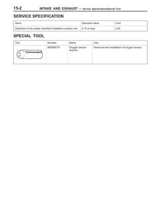
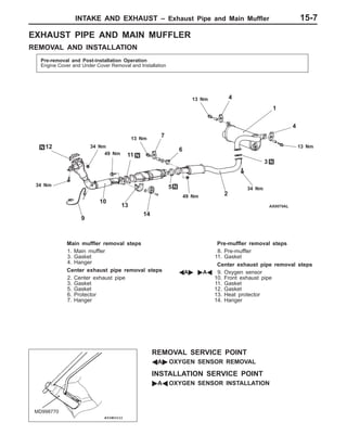
- Service specifications and special tools for tasks like oxygen sensor removal
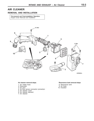
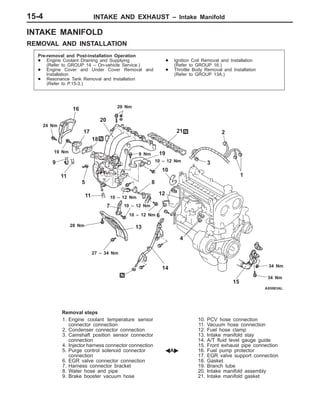
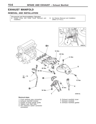
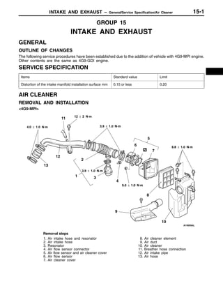
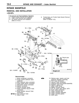
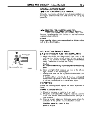
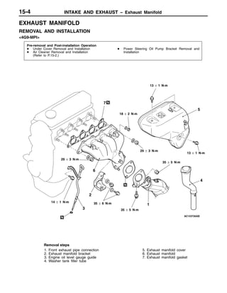
- Removal and installation steps for components like the air cleaner, intake manifold, exhaust manifold, and exhaust pipe/muffler
- Inspection procedures for parts such as checking for distortion on manifold surfaces
The document provides detailed removal and installation instructions, specifications, and points to note for servicing intake and exhaust systems.