Downloaded 13 times

![7
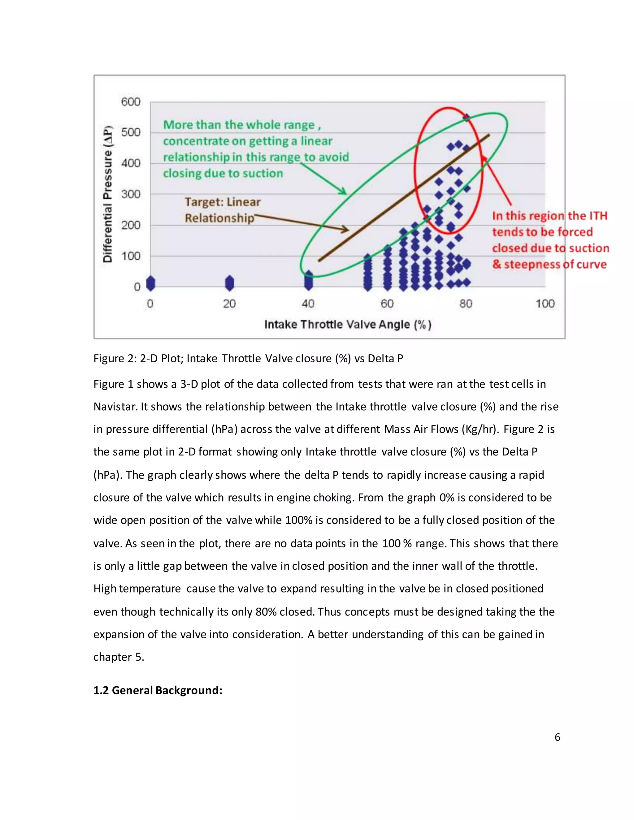
This project is assigned by the Aftertreatment department at Navistar. The
Aftertreatment department at Navistar deals with trying to achieve high Catalyst Inlet
temperatures in order to meet the EPA requirements. The target exhaust out temperatures
are tried to achieve by playing around with the Injection timings, EGR valve technology,
using the Intake Throttle and a Turbocharger. The target exhaust temperature going into
the Diesel Oxidation Catalyst is 275ºC - 300ºC, where as the target exhaust temperature
going into the Diesel Particulate Filter is 540ºC - 600ºC. The Target Diesel Oxidation
Temperature is needed to oxidize Carbon Monoxide (CO), Hydrocarbons (HC) and organic
fraction of diesel particulates (SOF). The Oxidation takes place as follows:
HC + O2 = CO2 + H2O ……. (I)
CO + 1/2O2 = CO2……….. (II)
2SO2 + O2 = 2SO3……… (III a)
SO3 + H20 = H2SO4……. (III b)
The target temperature going into the Diesel Particulate Filter is required for oxidation of
NOx. To read about the effects of catalysts on NOx refer Appendix [ ].
1.3 Regeneration Strategy Background:
Some of the strategies used by the companies to achieve target Exhaust out temperature for
regeneration are as follows:
1. Post Injection
Entirely new functions are performed by injection systems in engines with integrated
emission aftertreatment systems of Diesel Particulate Filters. These devices require
regeneration to burn all the soot which is provided by high temperatures or by rich
exhaust gas of rich HC content. These are achieved by late fuel injection which is also
called post injection. Thus Post injection provides a certain amount of high exhaust](https://image.slidesharecdn.com/mee481finalreport-141116183406-conversion-gate01/75/Senior-Design-Project-B-S-Mechanical-Engineering-ITV-Research-and-analysis-7-2048.jpg)
![16
CHAPTER 5
CONCEPT GENERATION
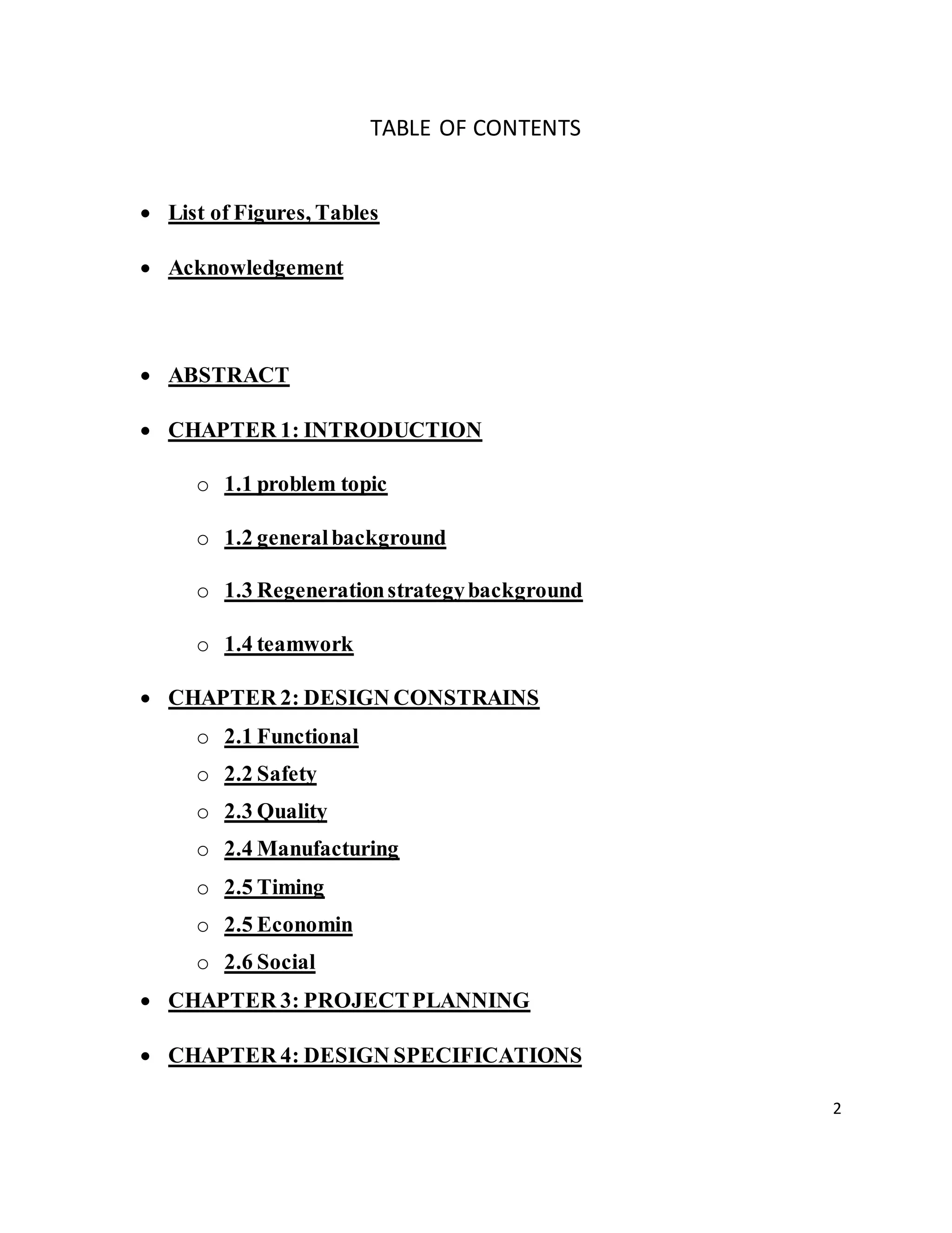
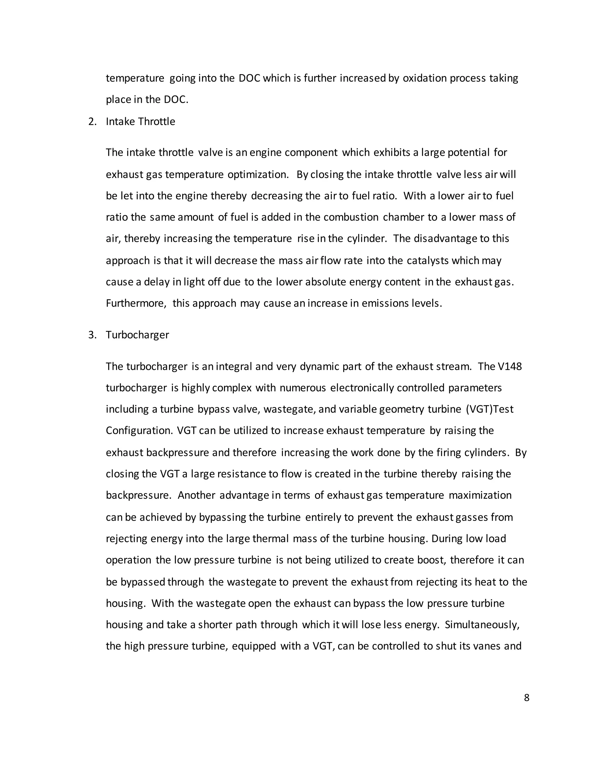
A. Orifice Plate
Orifice isnothingbutanopening,andthusa an orifice plate isa valve ora plate withan
opening.
Figure 5: Concept1: Orifice Plate
Thisis a valve whichbasicallyhasahole init.Where the hole needstobe designed?This
isnot determinedyet.Itcan be determinedwithfurthercalculations.
How doesan orifice plate help?
Since the Valve hasa hole inthe centerit allowsairincreasesairspeedsince ithastopass
througha smallerportion.Since the airhasto increase itsspeedtopassthrougha smallergap,
it resultsinreducedinternalpressurewhichmeansreducedDeltaP.ThusIf the DeltaP across
the valve iscontrolled,thenthiswill preventthe valve fromclosingdue tosuction.Some of the
calculationsthatwere lookedintothatwouldbe appliedtothisdesigntoprove whetherit
worksor nowis as follows.Thesecalculationswere basedoff of the original Fluidequationsin
Appendix [].
Orifice](https://image.slidesharecdn.com/mee481finalreport-141116183406-conversion-gate01/75/Senior-Design-Project-B-S-Mechanical-Engineering-ITV-Research-and-analysis-16-2048.jpg)
![17
The bestway to start aboutgoingaheadwiththisconceptwouldbe to talkto the
calibrationdepartmenttocheck,whatthe DeltaP requirementisata certainflow rate and at a
certainintake throttle angle.Thusthe minimumdiameterrequiredtomeetthe above targets
can be calculated.A numberof calculationscanbe done fordifferentcombinationsof flowrates
and intake throttle closure.The diameterof the openingcanbe determinedbasedoff of the
differentcalculationsperformed.
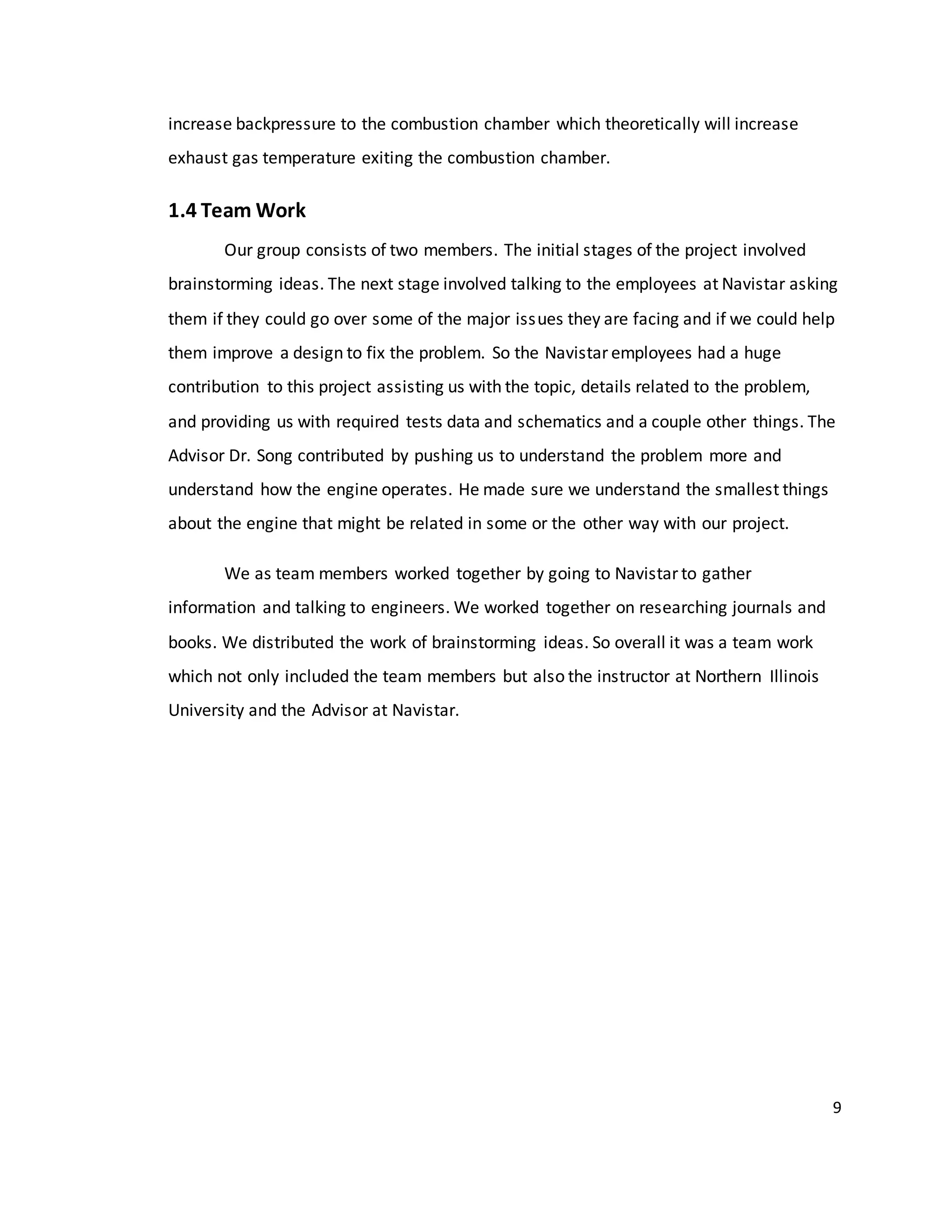
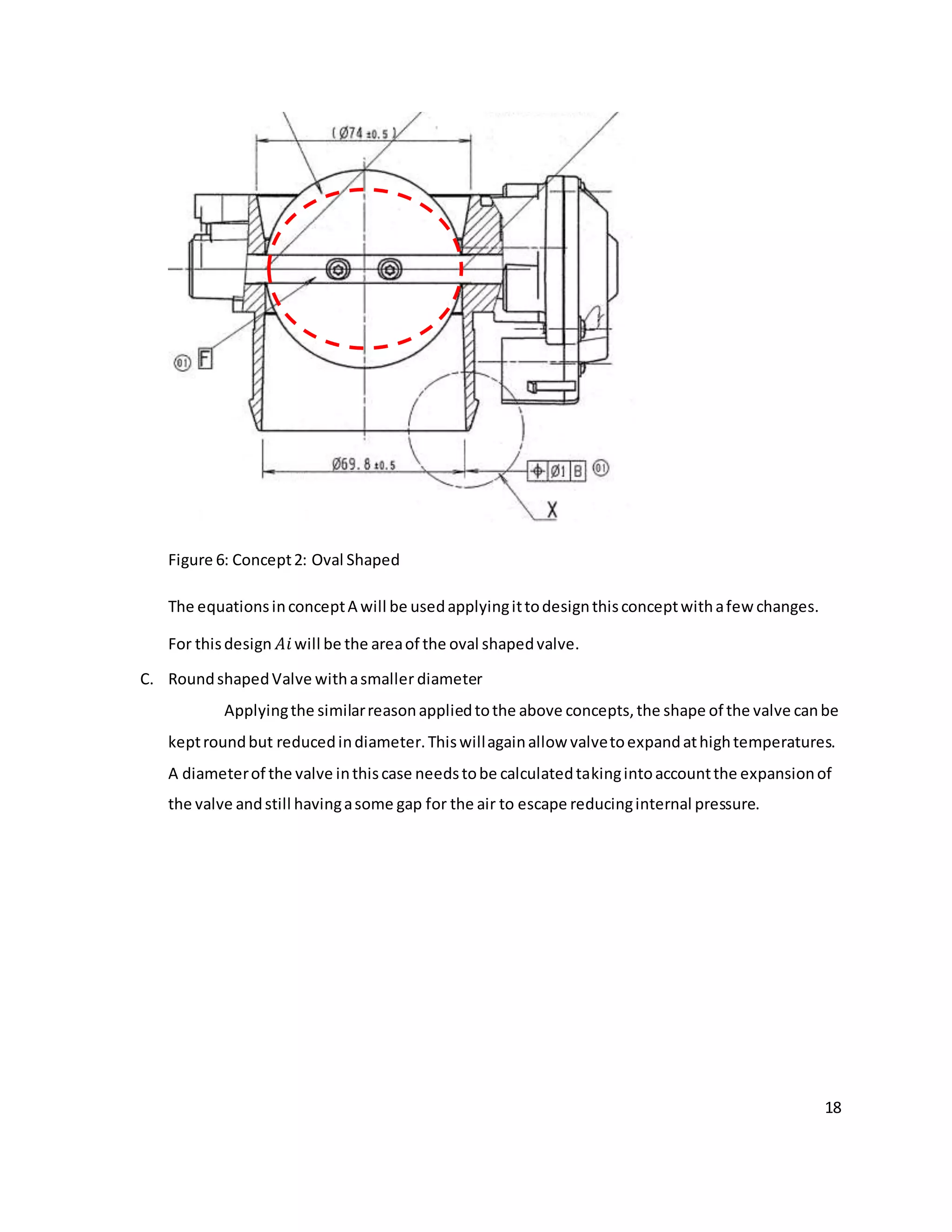
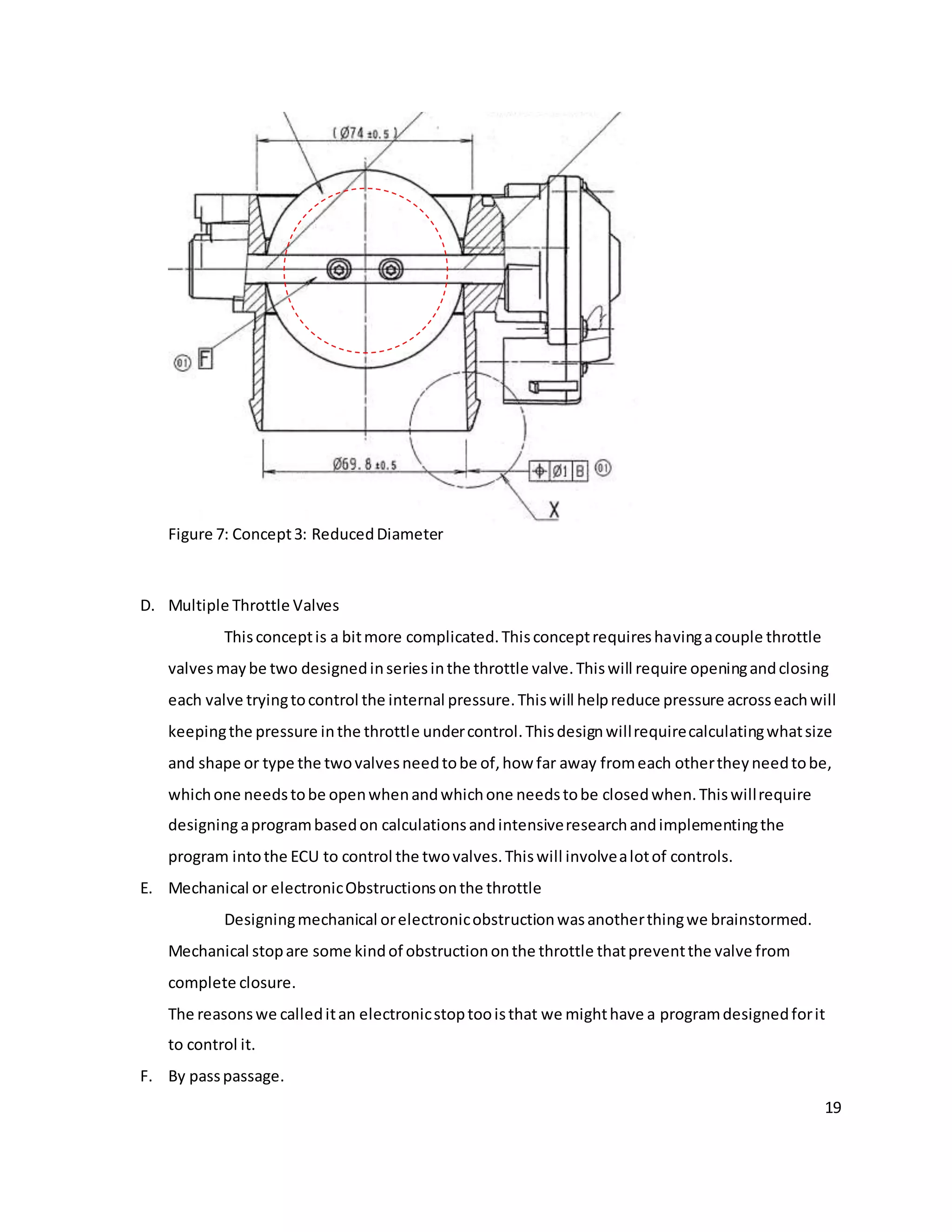
B. Oval shapedValve
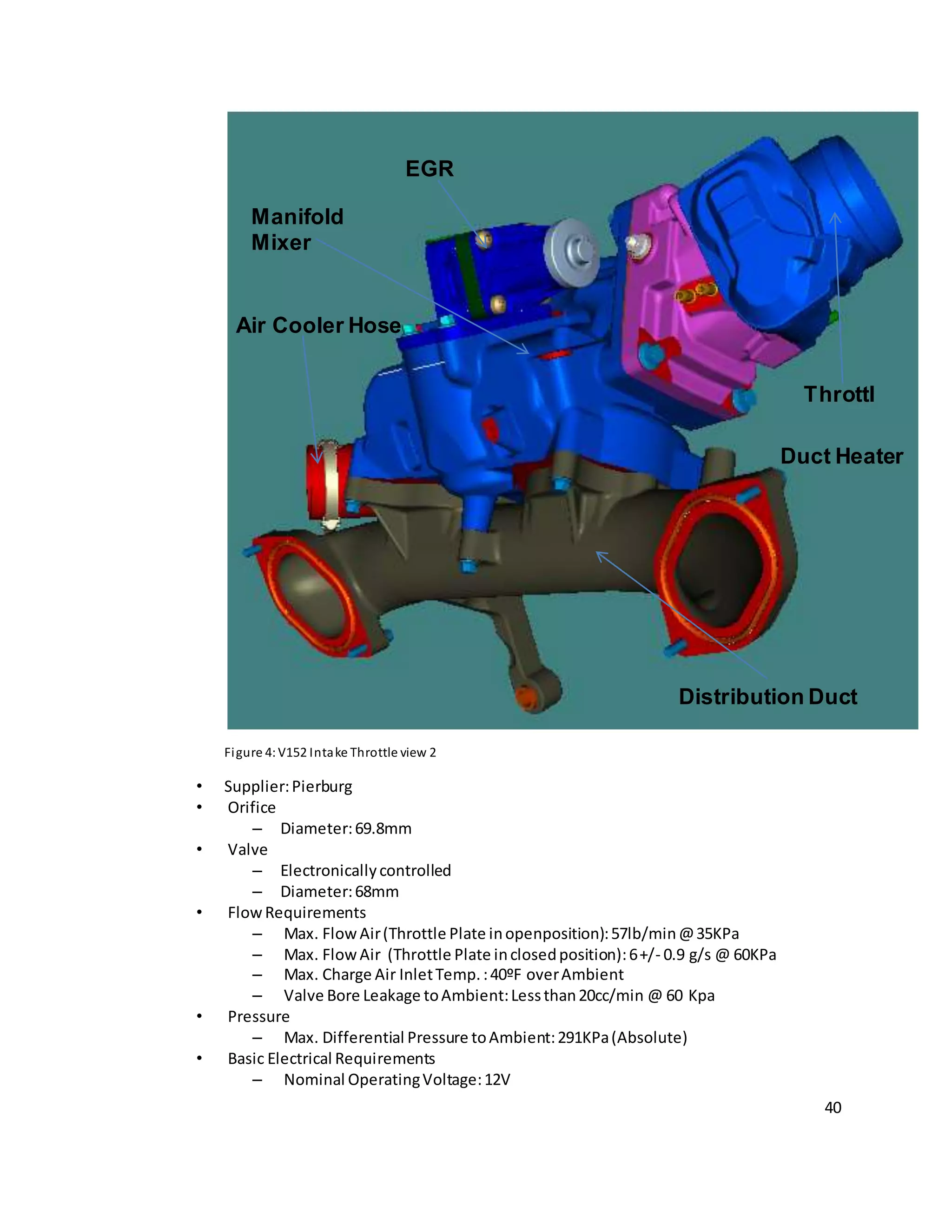
The presentIntake throttle valve isroundshaped.The presentthrottle valve hasa
diameterof 68mm as seeninAppendix[].The orifice aroundthe valveis69.8mm.Thus there isa
onlya 1.8mm gap betweenthe orifice platein closedpositionandthe throttle orifice.Athigh
temperaturesthe valve tendstoexpand,becauseof whichduringarapidincrease inDeltaP,the
throttle tendstoshutdownat 80% valve closure insteadof closingcompletelyat100% closure.
Thus reducingthe shape bymakingitoval mightbe beneficial.Thiswillnotonlygive the valve a
greaterexpansiongap.Anotherthingthatneedstobe lookedintowhile creatingthisdesignis
that dimensionsof the valve needtobe calculatedtakingintoaccountthatevenafterexpansion
of the valve athightemperaturesthere will some gapforthe air to escape whichwill prevent a
rapidrise of pressure differential acrossthe valve thuspreventingthe valvefromshuttingdown
due to suctionfurtherpreventingthe enginefromchoking.](https://image.slidesharecdn.com/mee481finalreport-141116183406-conversion-gate01/75/Senior-Design-Project-B-S-Mechanical-Engineering-ITV-Research-and-analysis-17-2048.jpg)

![29
APPENDIX C
EGR
EGR Control Valves
The EGR rate inearlyEGR systemswascontrolledusingaproperlysized ratecontrolorifice,in a design
resemblingthe systeminFigure 1.While averysimple solution,the orifice wasnotable toprovide the
necessaryflexibilityincontrollingthe EGRrate. Withtime,the orifice wasreplacedbyacontrol valve,
whichacts as a variable orifice,thusprovidingthe necessaryflexibility.
EGR valvesutilize anumberof differentdesigns.Some valvesare apoppetstyle,whileothershave
adopteda rotary type design.Because of the mechanismof valve actuation,EGRvalvesare dividedinto
twocategories:
1. Pneumaticvalves,and
2. Electricvalves.
PneumaticvalveswerecommoninEGR systemsforlight-dutyvehicles.Diesel carsinthe 1990s utilized
almostexclusivelypneumaticEGRvalves,butnewerdieselcarmodelsincreasinglyadoptelectricEGR
valves.Electricvalve actuationwasthe standardmethodusedinEGRsystemsforheavy-dutyengines
since theirintroductioninthe 2000s.
Witha pneumaticEGRvalve,the electricactuatingsignal fromthe enginecontrol module(ECM) is
convertedbyan electro-pneumaticconverterintoapneumaticvacuumsignal.Whenthe pneumaticEGR
valve isexposedtovacuum(producedbyavacuumpump),itresultsinthe requiredvalve position.A
disadvantage of the pneumaticvalveisahysteresisinthe characteristiccurve betweenvalve opening
and valve closing[Flaig2000].
In electricEGR valves,the valve modulationisperformedusinglinearsolenoidsorsteppermotors.An
example EGRvalve forheavy-dutyenginesisshowninFigure 2.
Figure 2. Prototype of aProductionStyle EGR Valve
Lucas Control Systems](https://image.slidesharecdn.com/mee481finalreport-141116183406-conversion-gate01/75/Senior-Design-Project-B-S-Mechanical-Engineering-ITV-Research-and-analysis-29-2048.jpg)
![30
Withthe electricEGRvalve,the ECMsendsa control signal to the electronicsintegratedinthe EGR
valve.Insome designs,aHall sensorisusedforpositionfeedbackforcontrol of the valve,resultingin
hysteresis-free openingandclosingof the valve andina linearcharacteristiccurve.ElectricEGRvalves
mustmeetdemandingoperational requirements:actuatingspeedsof lessthan50 ms at engine
compartmenttemperaturesof upto140°C were reportedinlight-dutyapplications[Flaig2000].
Controllingthe EGRvalve iseasilyaccommodatedthroughthe ECM.Many functionsare sharedbetween
engine andEGR valve control.Inputsof engine speed,torque (oftensubstitutedforwithintakemanifold
pressure),throttleposition,andintake manifoldtemperature are justafew of the sharedsignals
betweenbothengine andEGR control.
In some applications(e.g.,2004 7.3 literNavistarengine) anairflow sensorisusedtocontrol EGR rates.
At a givenspeedandloadcondition,the freshairsignal providedbythe airflow sensorforthe no-EGR
conditionisreducedbyopeningthe EGRvalve.The signal correspondingtothe reducedfreshairflowis
usedas feedback indicatingthe properEGRrate or leadingtofurtheradjustmentinEGRvalve position
to obtaina predeterminedEGRrate.In general,aproductionEGR systemmaynotneedfullydedicated
sensors,butmayshare control signalswithexistingsensors.We willreturntothe topicof EGR control
later.
The EGR valve isoftena separate componentinstalledinthe exhaustpiping.Insome designs,however,
the valve can be integratedwithvariouspartsof the engine.A valve integratedwiththe exhaust
manifoldis showninFigure 3[Haerter1994].
Figure 3. EGR Valve/IntakeManifoldIntegral Design
EGR Coolers
The heat absorbedfromthe combustionprocessisproportionaltoEGR rate,its specificheat,andthe
difference betweencombustionandEGR temperatures.Hence,coolingthe EGR streamallowsfor
greaterheatabsorptionfromthe combustionprocesswhichleadstoalowerrate of NOx formation.In
addition,coolerEGRoccupieslessvolume inthe inletsystem.LowerEGRvolume displacesasmaller
fractionof freshfilteredintakeair,thusdisplacinglessO2,whichhelpsmaintaincombustionefficiency.](https://image.slidesharecdn.com/mee481finalreport-141116183406-conversion-gate01/75/Senior-Design-Project-B-S-Mechanical-Engineering-ITV-Research-and-analysis-30-2048.jpg)
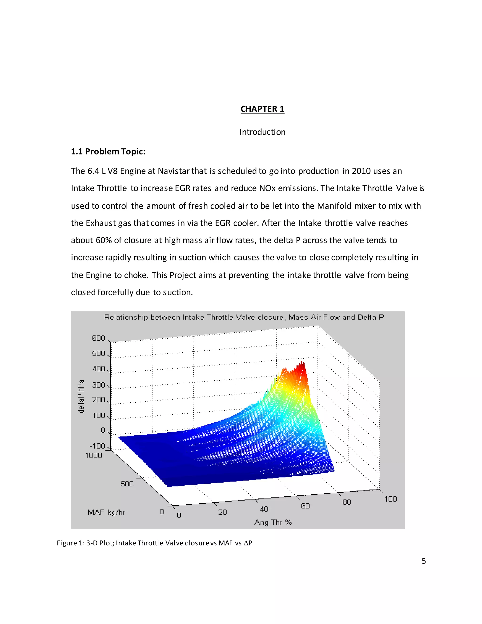
![31
A schematicrepresentationof anEGR coolerisshowninFigure 4. A startingpointformany EGR cooler
designshasbeenthe shell-and-tubeheatexchanger.Exhaustgasflowsthroughthe tubesof the heat
exchangerwhile the coolant—jacketwater—flowsinthe shell.
Figure 4. SchematicDiagramof EGR Cooler
Coolereffectiveness ismeasuredbythe ratioof the actual heattransfer across the coolerto the
maximumheattransferthatwouldbe potentiallypossible consideringthe temperaturesof the exhaust
gas and the coolant(i.e.,whenthe outletgastemperature becomesequaltothe inletcoolant
temperature):
(1)ε= Q/Qmax = (Tg,in - Tg,out)/(Tg,in - Tc,in)
Heat exchangergeometrymayneedtobe consideredinapplyingEquation(1).Onlycounterflow heat
exchangers,suchasthat showninFigure 4 (butof infinitelengthorinfinitelyhighheattransfer
coefficient),couldprovidean effectivenessof 1 usingthisequation.Forparallelflow coolers,Tc,in could
be replacedbyTc,out to representthe lowesttemperature towhichthe exhaustgascouldbe cooled.
Coolerswithmixedflowpatternscanbe designed,wherethe minimumpossible outletgastemperature
issomewhere betweenTc,in and Tc,out.
However,if one considersthe heatexchangertobe a blackbox,thenEquation(1) couldbe appliedto
any heatexchangerregardlessof geometry.Itwouldthencompare anygivenheatexchangerdesignto
the infinite lengthcounterflowarrangementthatwouldinprinciple provide maximumheattransfer.
Thisapproach isoftentakenforEGR coolers[Hoard2007][Kowada 2006].
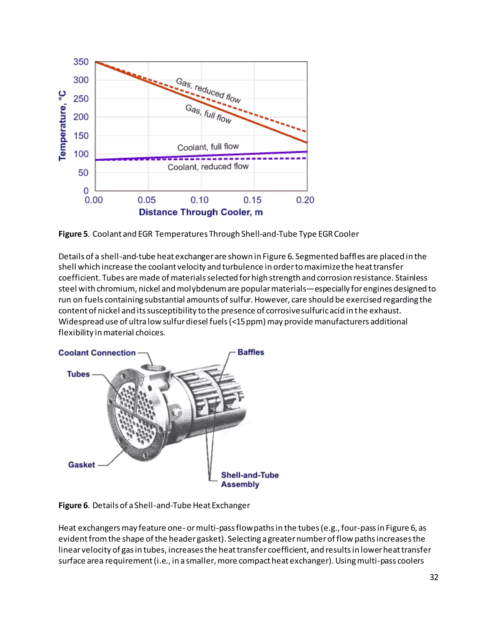
An example temperature profileandthe effectof coolantflow rate througha parallel flow shell-and-
tube EGR coolerare showninFigure 5 [Charlton1998]. In thiscase,as the coolantflow rate decreases
the effectiveness(relative tothe infinite lengthcounterflow arrangement)dropsfromabout81% to
72%.](https://image.slidesharecdn.com/mee481finalreport-141116183406-conversion-gate01/75/Senior-Design-Project-B-S-Mechanical-Engineering-ITV-Research-and-analysis-31-2048.jpg)
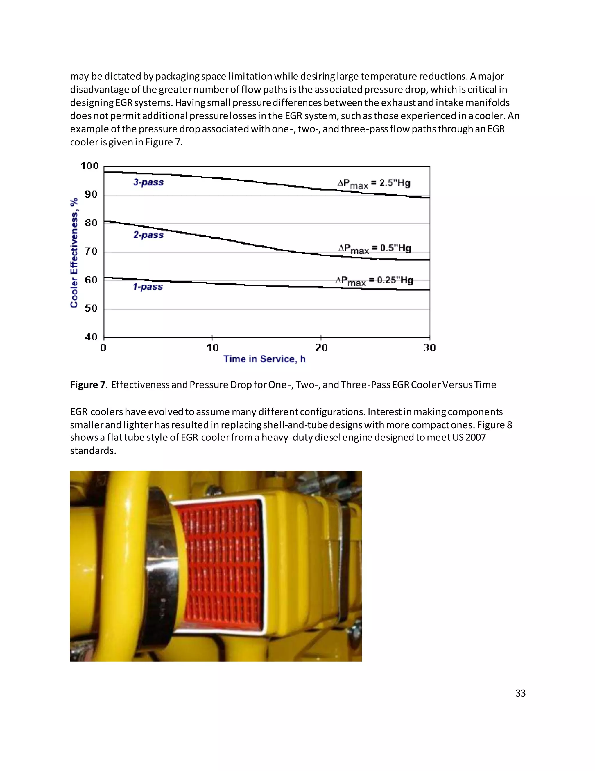
![34
Figure 8. FlatTube Style EGR Cooler
(Caterpillar2007 C15 ACERT engine)
Compactnessratio quantifiesthe heattransfersurface areaperunitvolume of the heatexchanger.In
some EGR coolers,more compactdesignisachievedthroughthe use of finsonthe gasside.Tube andfin
designscanhave compactnessratiosupto about 330 m2
/m3
.Plate andfincoolers—suchasthatshown
inFigure 9—can have compactnessratiosabove 1000 m2
/m3
.
Figure 9. CompactEGR CoolerAssemblyforLight-DutyApplications
(Source:Pierburg)
The EGR coolerinFigure 9, intendedforlight-dutyapplications,ismade fromdie castaluminum[Breuer
2007]. The exhaustgasfollowsaU-shapedflow patternthroughthe coolershell andpastthe fins.The
coolershell issurroundedbyenginecoolant.Thiscompactdesignisalsoveryefficient,withheat
transfercoefficientsonthe orderof 3000 W/m2
Kon the coolantside,andon the orderof 300 W/m2
Kin
the gas. Highheat transferratesare alsostimulatedbythe use of aluminum, whichhasa significantly
higherheatconductivitythanstainlesssteel.
Two-Stage Cooling.The practical lowtemperature limittowhichanEGR coolercan cool the recirculated
exhaustgaswill be somewhathigherthan the inlettemperature of the coolingmedium.ForanEGR
coolerusingengine coolantasa coolingmedium,thistemperature will be limitedbythe engine coolant
temperature—usuallyinthe range of 70-90°C. If lowerEGR temperaturesare required,asecondcooler
that usesambientairas a coolingmediumwouldbe required.Thisapproach—takenbyInternational on
some of theirUS 2007 enginesandbyScaniaforits Euro V engines—presentssomechallengessuchas
minimizingthe effectsof condensedwatertopreventcorrosionandfreezing.](https://image.slidesharecdn.com/mee481finalreport-141116183406-conversion-gate01/75/Senior-Design-Project-B-S-Mechanical-Engineering-ITV-Research-and-analysis-34-2048.jpg)
![35
CoolerBypass. CoolingEGR may notalwaysbe desirable.Forinstance,incoldweatherconditionswhere
EGR iscooledbelowthe dewpointtemperature,condensate mayformandmix withexhaustcontaining
sulfurandnitrogencompounds.The mixture of condensate andexhaustcanproduce acidsthat couldbe
corrosive tocomponentsof the EGR systemaswell asotherparts of the engine.Condensationof sulfur
speciesinEGR coolersandthe associatedcorrosionissueshave beenthe subjectof anumberof studies
[McKinley1997][Kreso1998b].
Some designsallowforbypassingthe EGRcoolerin coldtemperature aswell asat some driving
conditions,suchasidle orno load.Thispractice has oftenimprovedidle/noloadandpartloadfuel
economy,aswell asreducingHC andCO emissions.Itisalsoaimedatreducingthe formationof acidic
condensate thatmayimpairengine componentsdurability.A bypassarrangementalsoallowsbetter
control of EGR temperature byallowingforthe mixingof differentproportionsof cooledanduncooled
EGR. A coolercore withan integratedbypasspassage isshowninFigure 10[Beck2007]. A flapat the
inletof the coolerdirectsEGR to eitherflow throughthe coolingpassagesorthe bypasspassage.
Figure 10. EGR CoolerWithIntegratedBypassPassage
EGR coolerscanbe subjecttoconsiderable thermalstressfromthe highheatload.Toensure a long
service life,the housingstructuresof these coolerscanbe fittedwithanexpansionjoint,suchasan
expansionbeadora bellowsstructure,toprovide axial compensation.
Fouling.Foulingof the EGR coolerisa majorconcernbecause itcontributestolowercooler
effectiveness,aswell asincreasedpressureloss.Experimentsconductedonprototype coolershave
shownthat effectivenessdegradationisusuallylimitedtothe first20 to 30 hoursof use.The most rapid
drop of coolereffectivenessoccurswiththe cleancooler,inthe initial hoursof operation(thisisalso
apparentfromFigure 7 and Figure 11).
Foulingoccursprimarilyasa resultof the depositionof diesel particulate matter,aswell ascondensed
and/orpyrolysedhydrocarbons.Foulingtendstobe more severe inthe presence of “heavywetPM”,
whichismore common at lowNOx engine calibrations[Hoard2007]. The contaminantsare depositedon
the wallslargelydue tothermophoreticallyaugmentedconvective diffusion.Owingtothe insulation
effectof the depositlayer,the thermophoreticeffectlevelsoff whenthe depositbuildsup,leadingtoa](https://image.slidesharecdn.com/mee481finalreport-141116183406-conversion-gate01/75/Senior-Design-Project-B-S-Mechanical-Engineering-ITV-Research-and-analysis-35-2048.jpg)
![36
fallingrate of deposition.The resistance toheattransfercausedbyfoulingwillusuallyreachasteady-
state value forwhichempirical correlationsexist.One suchcorrelationis[Grillot1997]:
(2)R = 1.094 Cpart V-1.14
((Tg - Ts)/Tg)0.7
where:
R - steadystate foulingheattransferresistance,m2
K/W
Cpart - particle concentration,g/m3
V - gas flowvelocity,m/s
Tg - gas temperature,K
Ts - surface temperature,K.
A numberof approachescan be takento minimize the effectsof foulingincludingthe selectionof
appropriate geometriesthatinhibitexcessiveaccumulationof foulingmaterial andaddingextracapacity
that isintendedtobe lostto foulingduringservice of the cooler.Increasingflow velocitythroughthe
coolerand loweringthe temperature difference betweenthe gasandthe heatexchangersurface—as
suggested byEquation(2)—mayalsobe usedtominimizefouling.
An effective measure tocontrol foulingistoreduce the concentrationof particlesandother
componentsinthe EGR that may accumulate inthe heatexchanger.Forenginesequippedwithadiesel
particulate filter(DPF),anLPLEGR configurationcanbe used,where cleanexhaustgasisrecirculated
fromthe outletside of the filter(thisapproachwastaken,forexample,in2007 CaterpillarACERT
onroadengines).However,foulingmayremainaproblemforenginesthatrecirculate exhaustgasfrom
the exhaustmanifold.While aparticulate filtercouldbe placedinthe EGR line upstreamof the cooler,
the problemsof pluggingandkeepingthe filtercleanpresentasignificantchallenge.
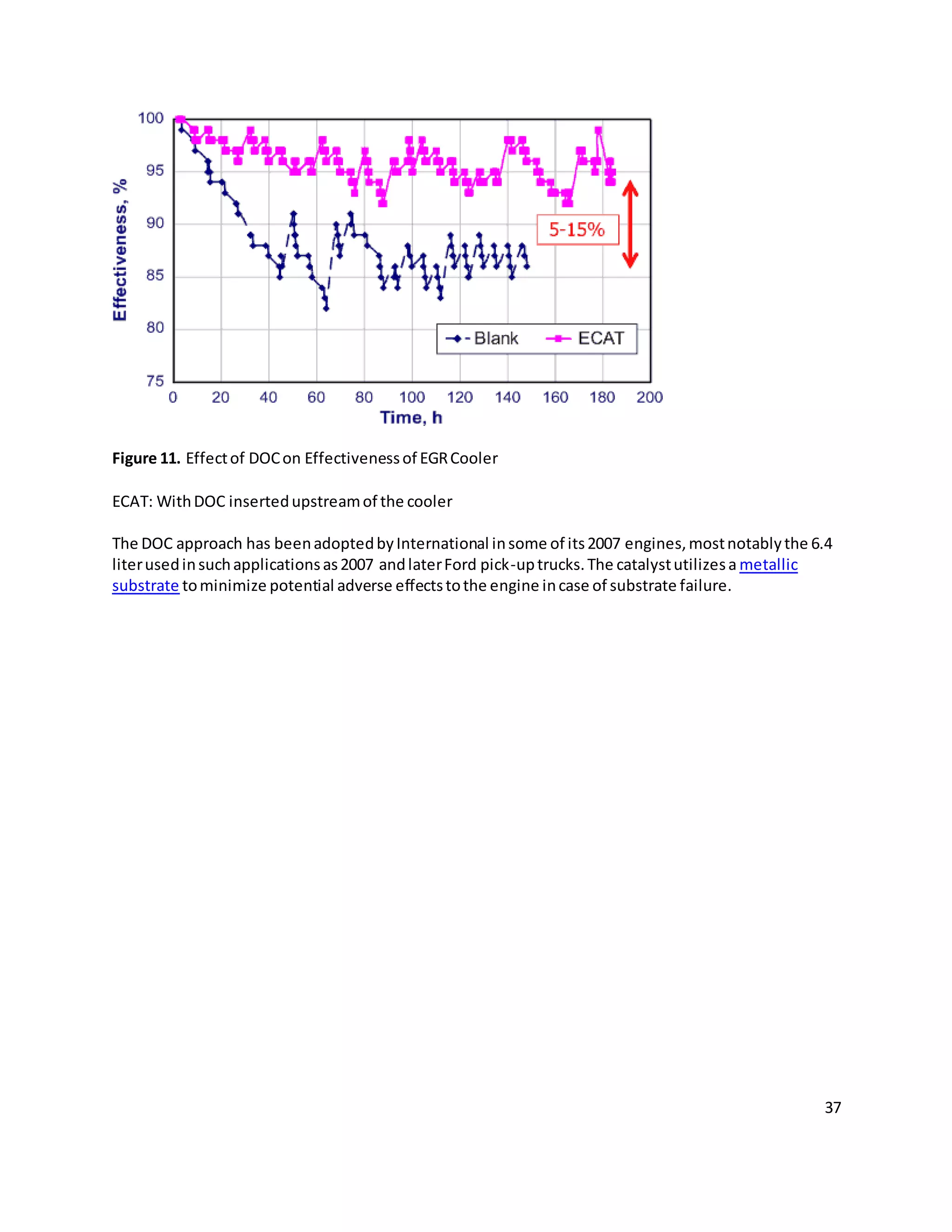
A more practical approach isto inserta diesel oxidationcatalyst(DOC) intothe EGRline upstreamof the
cooler.While notprovidingthe same levelof foulingprotectionasafilter,the catalystcansignificantly
reduce degradationof heattransfereffectivenessinanEGR cooler,as illustratedinFigure 11[Tyo
2007][Hoard 2007]. The coolereffectivenessdatawascollectedoveranengine cycle speciallydesigned
to testEGR coolerfouling.The DOCcan alsoprovide anadditional benefitof protectingthe EGRvalve
fromsticking.](https://image.slidesharecdn.com/mee481finalreport-141116183406-conversion-gate01/75/Senior-Design-Project-B-S-Mechanical-Engineering-ITV-Research-and-analysis-36-2048.jpg)


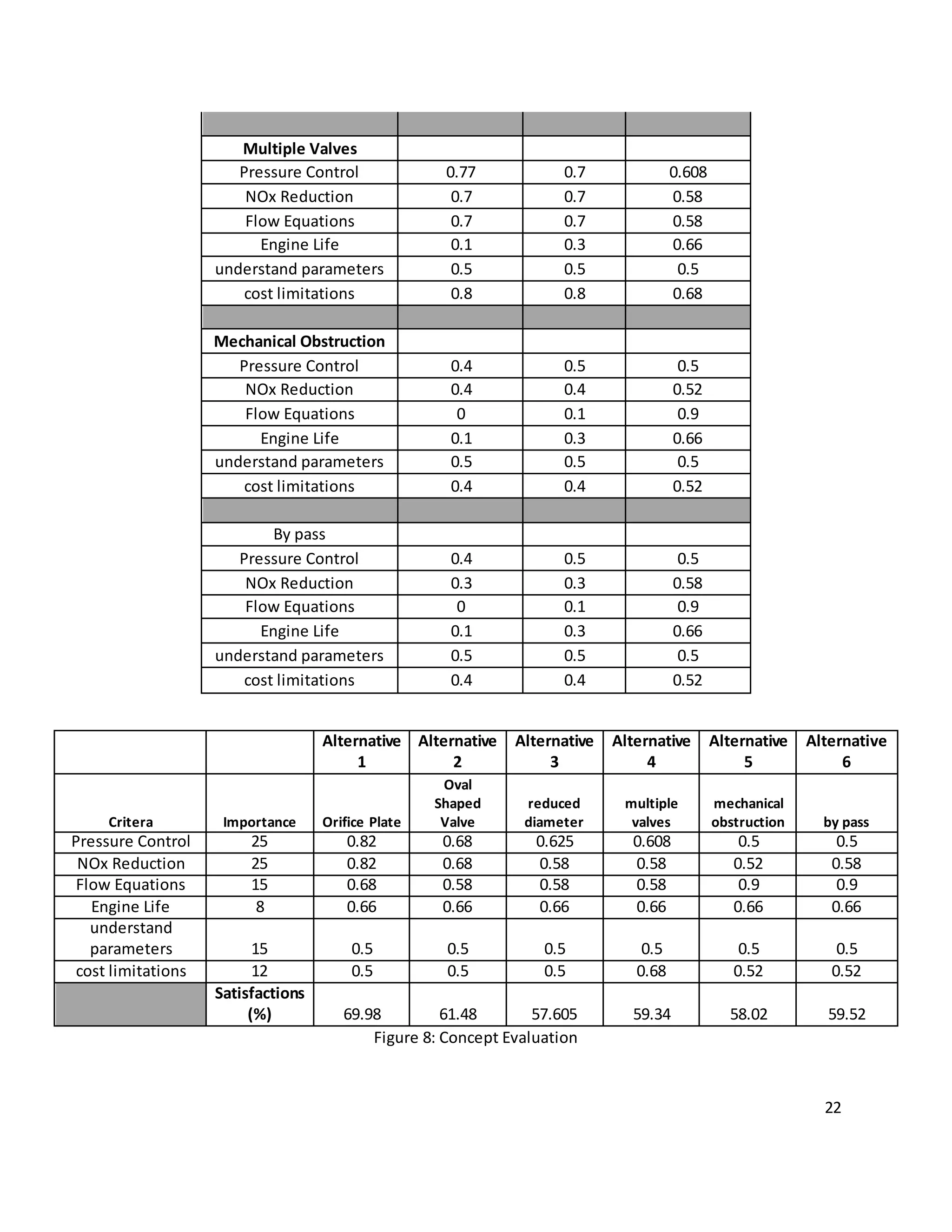
This document outlines the design of an intake throttle valve for a Navistar engine. It discusses the current issues with rapid closure of the throttle valve due to increasing pressure differential. Three concepts are proposed to address this - an orifice plate valve with a hole, an oval shaped valve, and a reduced diameter valve. Calculations of fluid flow and pressure differential would be used to select the best concept to prevent forced closure while meeting performance targets. Testing of a prototype part would then validate the chosen design.


