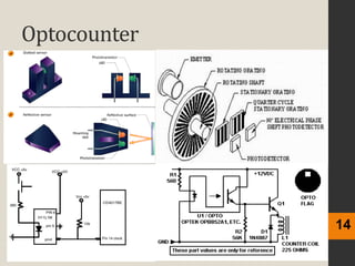
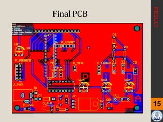
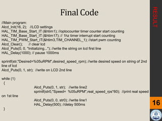
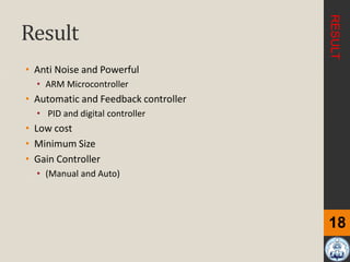
Controlling DC Motor speed, Using ARM
Microcontroller
Department of Biomedical Engineering
Faculty of Engineering
University of Isfahan
Seyed Yahya Moradi, Farzad Shahi,ETC
1
Table of Contents
Application of Dc Motor Controller
DC Motor Modeling
Control System Principles
ARM Microcontroller
Motor Driver & Optocounter
Schematic and PCB of the system
Conclusion
For many years the motor controller was a box which provided the motor
speed control and enabled the motor to adapt to variations in the load.
Designs were often lossy or they provided only crude increments in the
parameters controlled.
Application:
• Fans in cooker hoods
• Robotic Arms
• Surgery Robots
• Fan controller
• Medical Application (Electrocauter, ...)
• Drums and pumps in washing machines
• Compressors and fans in refrigerators
2
Applicationof Dc MotorController
ABSTRACT
3
Applicationof This Purpose
ABSTRACT
DC Motor Modeling
DC Motor plays a crucial role in research, industry and laboratory experiments
because of their low cost.
The position of the motor can be controlled by three methods namely terminal
voltage control method, armature rheostat control method and flux control
method. Here in this paper terminal voltage control method is employed.
4
Components of DC Motor
DC Motor Transfer Function
DC Motor Model
INTRODUCTION
Control System Principles
5
Open Loop Systems (Manual Control)
In an open loop control system the controlling parameters are fixed or set
by an oerator and the system finds its own equilibrium state.
Closed Loop Systems (Automatic Control)
Once the initial operating parameters have been set, an open loop system
is not responsive to subsequent changes or disturbances in the system
operating environment such as temperature and pressure, or to varying
demands on the system such as power delivery or load conditions.
©http://addhelium.com/site/wp-content/uploads/2013/11/MediaItem_258.jpg
INTRODUCTION
Block Control System
6
INTRODUCTION
ARM Microcontroller – STM 32
ARM, originally Acorn RISC Machine, later Advanced RISC Machine, is a family of
reduced instruction set computing (RISC) architectures for computer processors,
configured for various environments. British company ARM Holdings develops the
architecture and licenses it to other companies, who design their own products that
implement one of those architectures—including systems-on-chips (SoC) that
incorporate memory, interfaces, radios, etc. It also designs cores that implement this
instruction set and licenses these designs to a number of companies that incorporate
those core designs into their own products.
A RISC-based computer design approach means processors require fewer transistors
than typical complex instruction set computing (CISC) x86 processors in most personal
computers. This approach reduces costs, heat and power use. These characteristics
are desirable for light, portable, battery-powered devices—including, smartphones,
laptops and tablet computers, and other embedded systems
7
©http://addhelium.com/site/wp-content/uploads/2
INTRODUCTION
ARM Microcontroller
8
INTRODUCTION
Schematic of the system
9
• Push Button as input for ARM Microcontroller
• ICSP for programming PIC microcontroller
• Interface Precision Potentiometer
• Interface LCD (2x 16 Characters)
• Power supply for the circuit
• Interface L298D
METHOD
Interface LCD (2*16 Characters)
10
2*16 character LCD Connection of LCD
Pin Name Pin Function Connection
1 VSS Ground GND
2 VCC Positive Supply 5V
3 VEE Brightness -
4 RS Select Register RB7
5 R/W Select
Read/Write
GND
6 E Start
Read/Write
RB6
7 DB0 Data Bus PIN RB5
8 DB1 Data Bus PIN RB4
9 DB2 Data Bus PIN RB3
10 DB3 Data Bus PIN RB2
11 DB4 Data Bus PIN RB1
12 DB5 Data Bus PIN RC5
13 DB6 Data Bus PIN RC4
14 DB7 Data Bus PIN RC3
15 LED+ Backlight + 5V
16 LED- Backlight - GND
To use the LCD display, users have to solder
16 pin header pin to the LCD display. Figure
is a 2*16 character LCD and table 1 is all PIN
and connectors.
METHOD
Power supply for the circuit
11
User can choose either AC to DC adaptors or 12V to power up the
circuit. Higher input voltage will produce more heat at LM7805 voltage
regulator.
There are two type of power connector for the circuit, DC plug (J1)
and 2510-02 (Power Connector). Normally AC to DC adaptor can be
plugged to J1 type connector
Power supply for the circuit
METHOD
Interface L298D
11
The L298 is an integrated monolithic circuit
in a 15-lead Multiwatt and PowerSO20
packages. It is a high voltage, high current
dual full-bridge driver designed to accept
standard TTL logic levels and drive
inductive loads such as relays, solenoids,
DC and stepping motors. Two enable
inputs are provided to enable or disable the
device independently of the input signals.
The emitters of the lower transistors of
each bridge are connected together and
the corresponding external terminal can be
used for the connection of an external
sensing resistor. An additional supply input
is provided so that the logic works at a
lower voltage.
METHOD
Interface L298D
12
METHOD
Optocounter
13
Optocounter
14
Final PCB
15Figure 11: PID Gains and Angle Adjusters
circuit
RESULT
Final Code
16
RESULT
//Main program:
Alcd_Init(16, 2); //LCD settings
HAL_TIM_Base_Start_IT (&htim1); //optocounter timer counter start counting
HAL_TIM_Base_Start_IT (&htim17); // 1hz timer interrupt start counting
HAL_TIM_PWM_Start_IT(&htim3,TIM_CHANNEL_1); //start pwm counting
Alcd_Clear(); // clear lcd
Alcd_Puts(0, 0, "Initializing..."); //write the string on lcd first line
HAL_Delay(1000); // pause 1000ms
sprintf(str,"Desired=%05uRPM",desired_speed_rpm); //write desired speed on string of 2nd
line of lcd
Alcd_Puts(0, 1, str); //write on LCD 2nd line
while (1)
{
Alcd_Puts(0, 1, str); //write line2
sprintf(str0,"Speed= %05uRPM",real_speed_rps*60); //print real speed
on 1st line
Alcd_Puts(0, 0, str0); //write line1
HAL_Delay(500); //delay 500ms
}
Final HardWare
17
Result
• Anti Noise and Powerful
• ARM Microcontroller
• Automatic and Feedback controller
• PID and digital controller
• Low cost
• Minimum Size
• Gain Controller
• (Manual and Auto)
18
RESULT
References
1. Xue, D., C. Zhao, and Y. Chen. Fractional order PID control of a DC-motor with elastic shaft: a case
study. in Proceedings of American control conference. 2006.
2. Saranya, M. and D. Pamela, A real time IMC tuned PID controller for DC motor. International Journal of
Recent Technology and Engineering, 2012. 1(1): p. 65-70.
3. Kaya, I., IMC based automatic tuning method for PID controllers in a Smith predictor configuration.
Computers & chemical engineering, 2004. 28(3): p. 281-290.
4. Inaba, H., et al., Control apparatus for DC motor. 1978, Google Patents.
5. Leonhard, W., Control of a Separately Excited DC Machine. Control of Electrical Drives, 2001: p. 77-96.
6. Yeung, K. and J. Huang, Development of a remote-access laboratory: a dc motor control experiment.
Computers in Industry, 2003. 52(3): p. 305-311.
7. Naveenkumar, R. and D.P. Krishna, Low Cost Data Acquisition and Control using Arduino Prototyping
Platform and LabVIEW. International Journal of Science and Research, 2013. 2(2): p. 366-369.
8. Rubaai, A. and R. Kotaru, Online identification and control of a DC motor using learning adaptation of
neural networks. Industry Applications, IEEE Transactions on, 2000. 36(3): p. 935-942.
9. Zouari, F., K.B. Saad, and M. Benrejeb, Adaptive Internal Model Control of a DC Motor Drive System
Using Dynamic Neural Network. Journal of Software Engineering and Applications, 2012. 5(03): p. 168.
10. Rao, A.P.C., Y. Obulesu, and C.S. Babu, Robust Internal Model Control Strategy based PID Controller for
BLDCM. International Journal of Engineering Science and Technology, 2010. 2(11): p. 6801-6811.
11. Petráš, I., Fractional-order feedback control of a DC motor. Journal of Electrical Engineering, 2009.
60(3): p. 117-128.
12. Mazidi, M.A., et al., Pic microcontroller and embedded systems. 2005: Prentice-Hall, Inc.
13. Peatman, J.B., Design with PIC microcontrollers. 1997: Simon & Schuster Trade.
19
DC motor controlling

DC motor controlling

  • 1.
    Controlling DC Motorspeed, Using ARM Microcontroller Department of Biomedical Engineering Faculty of Engineering University of Isfahan Seyed Yahya Moradi, Farzad Shahi,ETC
  • 2.
    1 Table of Contents Applicationof Dc Motor Controller DC Motor Modeling Control System Principles ARM Microcontroller Motor Driver & Optocounter Schematic and PCB of the system Conclusion
  • 3.
    For many yearsthe motor controller was a box which provided the motor speed control and enabled the motor to adapt to variations in the load. Designs were often lossy or they provided only crude increments in the parameters controlled. Application: • Fans in cooker hoods • Robotic Arms • Surgery Robots • Fan controller • Medical Application (Electrocauter, ...) • Drums and pumps in washing machines • Compressors and fans in refrigerators 2 Applicationof Dc MotorController ABSTRACT
  • 4.
  • 5.
    DC Motor Modeling DCMotor plays a crucial role in research, industry and laboratory experiments because of their low cost. The position of the motor can be controlled by three methods namely terminal voltage control method, armature rheostat control method and flux control method. Here in this paper terminal voltage control method is employed. 4 Components of DC Motor DC Motor Transfer Function DC Motor Model INTRODUCTION
  • 6.
    Control System Principles 5 OpenLoop Systems (Manual Control) In an open loop control system the controlling parameters are fixed or set by an oerator and the system finds its own equilibrium state. Closed Loop Systems (Automatic Control) Once the initial operating parameters have been set, an open loop system is not responsive to subsequent changes or disturbances in the system operating environment such as temperature and pressure, or to varying demands on the system such as power delivery or load conditions. ©http://addhelium.com/site/wp-content/uploads/2013/11/MediaItem_258.jpg INTRODUCTION
  • 7.
  • 8.
    ARM Microcontroller –STM 32 ARM, originally Acorn RISC Machine, later Advanced RISC Machine, is a family of reduced instruction set computing (RISC) architectures for computer processors, configured for various environments. British company ARM Holdings develops the architecture and licenses it to other companies, who design their own products that implement one of those architectures—including systems-on-chips (SoC) that incorporate memory, interfaces, radios, etc. It also designs cores that implement this instruction set and licenses these designs to a number of companies that incorporate those core designs into their own products. A RISC-based computer design approach means processors require fewer transistors than typical complex instruction set computing (CISC) x86 processors in most personal computers. This approach reduces costs, heat and power use. These characteristics are desirable for light, portable, battery-powered devices—including, smartphones, laptops and tablet computers, and other embedded systems 7 ©http://addhelium.com/site/wp-content/uploads/2 INTRODUCTION
  • 9.
  • 10.
    Schematic of thesystem 9 • Push Button as input for ARM Microcontroller • ICSP for programming PIC microcontroller • Interface Precision Potentiometer • Interface LCD (2x 16 Characters) • Power supply for the circuit • Interface L298D METHOD
  • 11.
    Interface LCD (2*16Characters) 10 2*16 character LCD Connection of LCD Pin Name Pin Function Connection 1 VSS Ground GND 2 VCC Positive Supply 5V 3 VEE Brightness - 4 RS Select Register RB7 5 R/W Select Read/Write GND 6 E Start Read/Write RB6 7 DB0 Data Bus PIN RB5 8 DB1 Data Bus PIN RB4 9 DB2 Data Bus PIN RB3 10 DB3 Data Bus PIN RB2 11 DB4 Data Bus PIN RB1 12 DB5 Data Bus PIN RC5 13 DB6 Data Bus PIN RC4 14 DB7 Data Bus PIN RC3 15 LED+ Backlight + 5V 16 LED- Backlight - GND To use the LCD display, users have to solder 16 pin header pin to the LCD display. Figure is a 2*16 character LCD and table 1 is all PIN and connectors. METHOD
  • 12.
    Power supply forthe circuit 11 User can choose either AC to DC adaptors or 12V to power up the circuit. Higher input voltage will produce more heat at LM7805 voltage regulator. There are two type of power connector for the circuit, DC plug (J1) and 2510-02 (Power Connector). Normally AC to DC adaptor can be plugged to J1 type connector Power supply for the circuit METHOD
  • 13.
    Interface L298D 11 The L298is an integrated monolithic circuit in a 15-lead Multiwatt and PowerSO20 packages. It is a high voltage, high current dual full-bridge driver designed to accept standard TTL logic levels and drive inductive loads such as relays, solenoids, DC and stepping motors. Two enable inputs are provided to enable or disable the device independently of the input signals. The emitters of the lower transistors of each bridge are connected together and the corresponding external terminal can be used for the connection of an external sensing resistor. An additional supply input is provided so that the logic works at a lower voltage. METHOD
  • 14.
  • 15.
  • 16.
  • 17.
    Final PCB 15Figure 11:PID Gains and Angle Adjusters circuit RESULT
  • 18.
    Final Code 16 RESULT //Main program: Alcd_Init(16,2); //LCD settings HAL_TIM_Base_Start_IT (&htim1); //optocounter timer counter start counting HAL_TIM_Base_Start_IT (&htim17); // 1hz timer interrupt start counting HAL_TIM_PWM_Start_IT(&htim3,TIM_CHANNEL_1); //start pwm counting Alcd_Clear(); // clear lcd Alcd_Puts(0, 0, "Initializing..."); //write the string on lcd first line HAL_Delay(1000); // pause 1000ms sprintf(str,"Desired=%05uRPM",desired_speed_rpm); //write desired speed on string of 2nd line of lcd Alcd_Puts(0, 1, str); //write on LCD 2nd line while (1) { Alcd_Puts(0, 1, str); //write line2 sprintf(str0,"Speed= %05uRPM",real_speed_rps*60); //print real speed on 1st line Alcd_Puts(0, 0, str0); //write line1 HAL_Delay(500); //delay 500ms }
  • 19.
  • 20.
    Result • Anti Noiseand Powerful • ARM Microcontroller • Automatic and Feedback controller • PID and digital controller • Low cost • Minimum Size • Gain Controller • (Manual and Auto) 18 RESULT
  • 21.
    References 1. Xue, D.,C. Zhao, and Y. Chen. Fractional order PID control of a DC-motor with elastic shaft: a case study. in Proceedings of American control conference. 2006. 2. Saranya, M. and D. Pamela, A real time IMC tuned PID controller for DC motor. International Journal of Recent Technology and Engineering, 2012. 1(1): p. 65-70. 3. Kaya, I., IMC based automatic tuning method for PID controllers in a Smith predictor configuration. Computers & chemical engineering, 2004. 28(3): p. 281-290. 4. Inaba, H., et al., Control apparatus for DC motor. 1978, Google Patents. 5. Leonhard, W., Control of a Separately Excited DC Machine. Control of Electrical Drives, 2001: p. 77-96. 6. Yeung, K. and J. Huang, Development of a remote-access laboratory: a dc motor control experiment. Computers in Industry, 2003. 52(3): p. 305-311. 7. Naveenkumar, R. and D.P. Krishna, Low Cost Data Acquisition and Control using Arduino Prototyping Platform and LabVIEW. International Journal of Science and Research, 2013. 2(2): p. 366-369. 8. Rubaai, A. and R. Kotaru, Online identification and control of a DC motor using learning adaptation of neural networks. Industry Applications, IEEE Transactions on, 2000. 36(3): p. 935-942. 9. Zouari, F., K.B. Saad, and M. Benrejeb, Adaptive Internal Model Control of a DC Motor Drive System Using Dynamic Neural Network. Journal of Software Engineering and Applications, 2012. 5(03): p. 168. 10. Rao, A.P.C., Y. Obulesu, and C.S. Babu, Robust Internal Model Control Strategy based PID Controller for BLDCM. International Journal of Engineering Science and Technology, 2010. 2(11): p. 6801-6811. 11. Petráš, I., Fractional-order feedback control of a DC motor. Journal of Electrical Engineering, 2009. 60(3): p. 117-128. 12. Mazidi, M.A., et al., Pic microcontroller and embedded systems. 2005: Prentice-Hall, Inc. 13. Peatman, J.B., Design with PIC microcontrollers. 1997: Simon & Schuster Trade. 19