Downloaded 28 times
![10 | P a g e
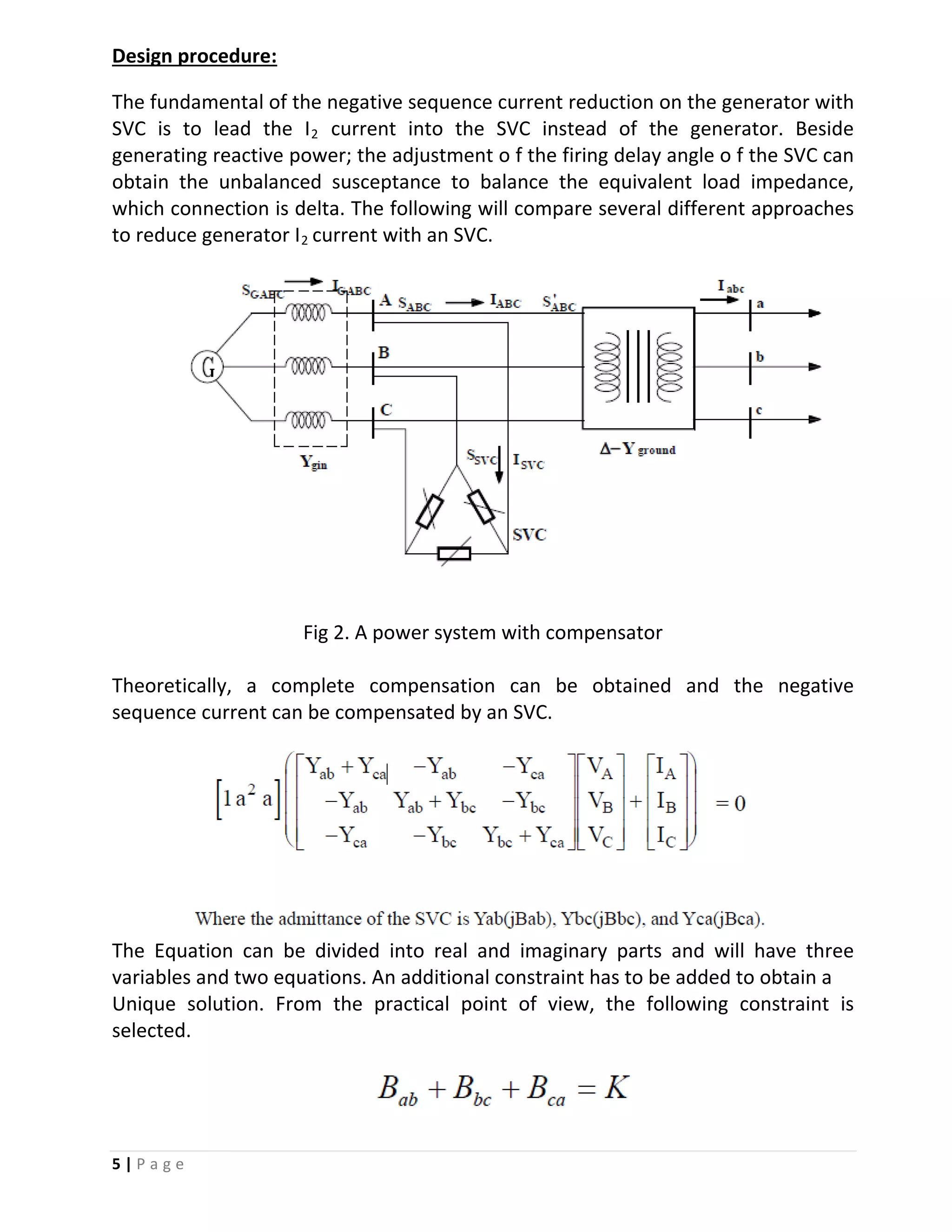
Source Code:
%% CASE:1- Without power factor correction
% Load data as provided
Pa= 0.4;
Qa= 0.3;
Sa= Pa+Qa*i;
Pb= 0.4;
Qb= 0.3;
Sb= Pb+Qb*i;
Pc= 0.4;
Qc= 0.3;
Sc= Pc+Qc*i;
% Terminal Voltage at Transformer primary
VA= 1;
VB= -0.5-0.866i;
VC= -0.5+0.866i;
% Terminal Voltage at Transformer secondary
Va= VA*(0.866025+0.5i);
Vb= VB*(0.866025+0.5i);
Vc= VC*(0.866025+0.5i);
a= -0.5+0.866i;
% Phase current, Transformer secondary side
Ia= conj(Sa/Va);
Ib= conj(Sb/Vb);
Ic= conj(Sc/Vc);
% Phase current, Transformer Primary side
IA = Ia*(0.866025-0.5i);
IB = Ib*(0.866025-0.5i);
IC = Ic*(0.866025-0.5i);
%Sequence current in system
Iseq = (1/3) * [1 a a^2; 1 a^2 a; 1 1 1]*[IA; IB; IC]; %
Iseq = [Iseq(1); Iseq(2); 0]; % As delta configuration will eliminate zero
serquence current.
I2= [real(Iseq(2)); imag(Iseq(2)); 0];
A= [1.5 -2.99 1.5; 2.598 -0.0001 -2.598; 1 1 1];
I2netbefore= Iseq(2)
B= inv(A)*I2;
Bab=B(1)
Bbc=B(2)
Bca=B(3)
A= [1 a^2 a];
V= [VA-VB 0 VA-VC; VB-VA VB-VC 0; 0 VC-VB VC-VA];
I2SVC= A*V*B
I2netafter = Iseq(2)-I2SVC](https://image.slidesharecdn.com/ee5374project2hardikparikh1001090431-160420210732/75/Design-of-a-3-phase-FC-TCR-Static-Var-Compensator-for-Power-factor-correction-and-Preventation-of-negative-sequence-current-10-2048.jpg)
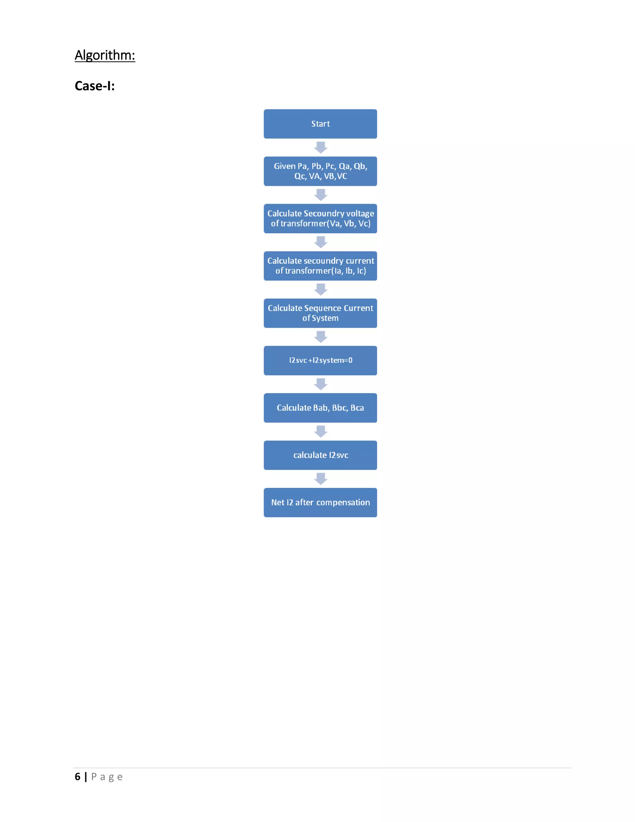
![11 | P a g e
%% CASE:2- With power factor correction
% Load data as provided
Pa= 0.4;
Qa= 0.3;
Sa= Pa+Qa*i;
Pb= 0.4;
Qb= 0.3;
Sb= Pb+Qb*i;
Pc= 0.4;
Qc= 0.3;
Sc= Pc+Qc*i;
% Terminal Voltage at Transformer primary
VA= 1;
VB= -0.5-0.866i;
VC= -0.5+0.866i;
% Terminal Voltage at Transformer secondary
Va= VA*(0.866025+0.5i);
Vb= VB*(0.866025+0.5i);
Vc= VC*(0.866025+0.5i);
a= -0.5+0.866i;
% Phase current, Transformer secondary side
Ia= conj(Sa/Va)
Ib= conj(Sb/Vb)
Ic= conj(Sc/Vc)
% Phase current, Transformer Primary side
IA = Ia*(0.866025-0.5i);
IB = Ib*(0.866025-0.5i);
IC = Ic*(0.866025-0.5i);
S1= VA*conj(IA);
P1= real(S1);
Q1= imag(S1);
% Phi1= atan(Q1/P1);
% PF1= cos(phi1);
P2=P1;
PF2= 0.8;
PF= 1; % As provided
Q2= P2*tan(acos(pf2))
Q3= Q1-Q2;
K= Q3/VA^2
% Q2new= Q3+Q2avg
pfnew= P2/(sqrt(P2^2+Q3^2))
%Sequence current in system
Iseq = (1/3) * [1 a a^2; 1 a^2 a; 1 1 1]*[IA; IB; IC]; %
Iseq = [Iseq(1); Iseq(2); 0] % As delta configuration will eliminate zero
serquence current.](https://image.slidesharecdn.com/ee5374project2hardikparikh1001090431-160420210732/75/Design-of-a-3-phase-FC-TCR-Static-Var-Compensator-for-Power-factor-correction-and-Preventation-of-negative-sequence-current-11-2048.jpg)
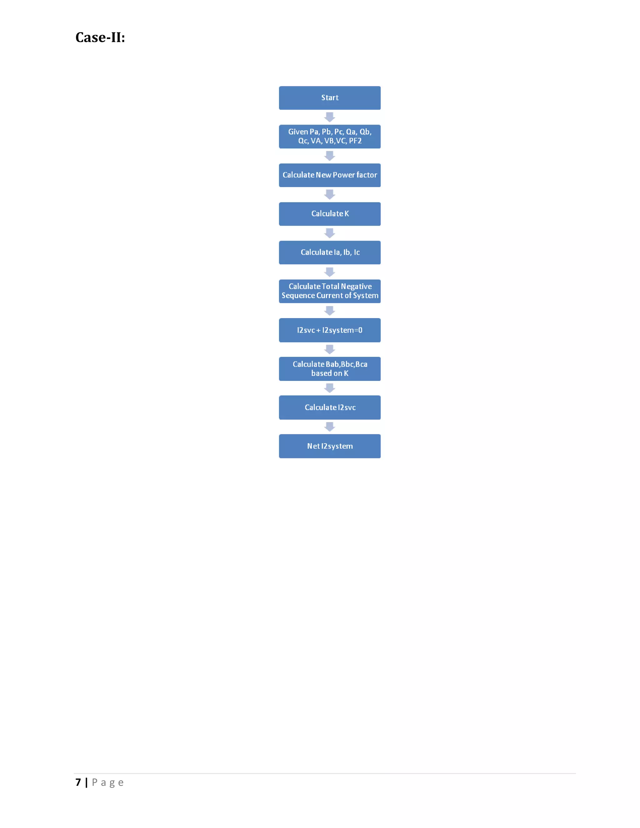
![12 | P a g e
I2= [real(Iseq(2)); imag(Iseq(2)); K];
A= [1.5 -2.99 1.5; 2.598 -0.0001 -2.598; 1 1 1];
B= inv(A)*I2
Bab=B(1)
Bbc=B(2)
Bca=B(3)
A= [1 a^2 a];
V= [VA-VB 0 VA-VC; VB-VA VB-VC 0; 0 VC-VB VC-VA];
I2SVC= A*V*B
I2net = Iseq(2)-I2SVC
Conclusion:
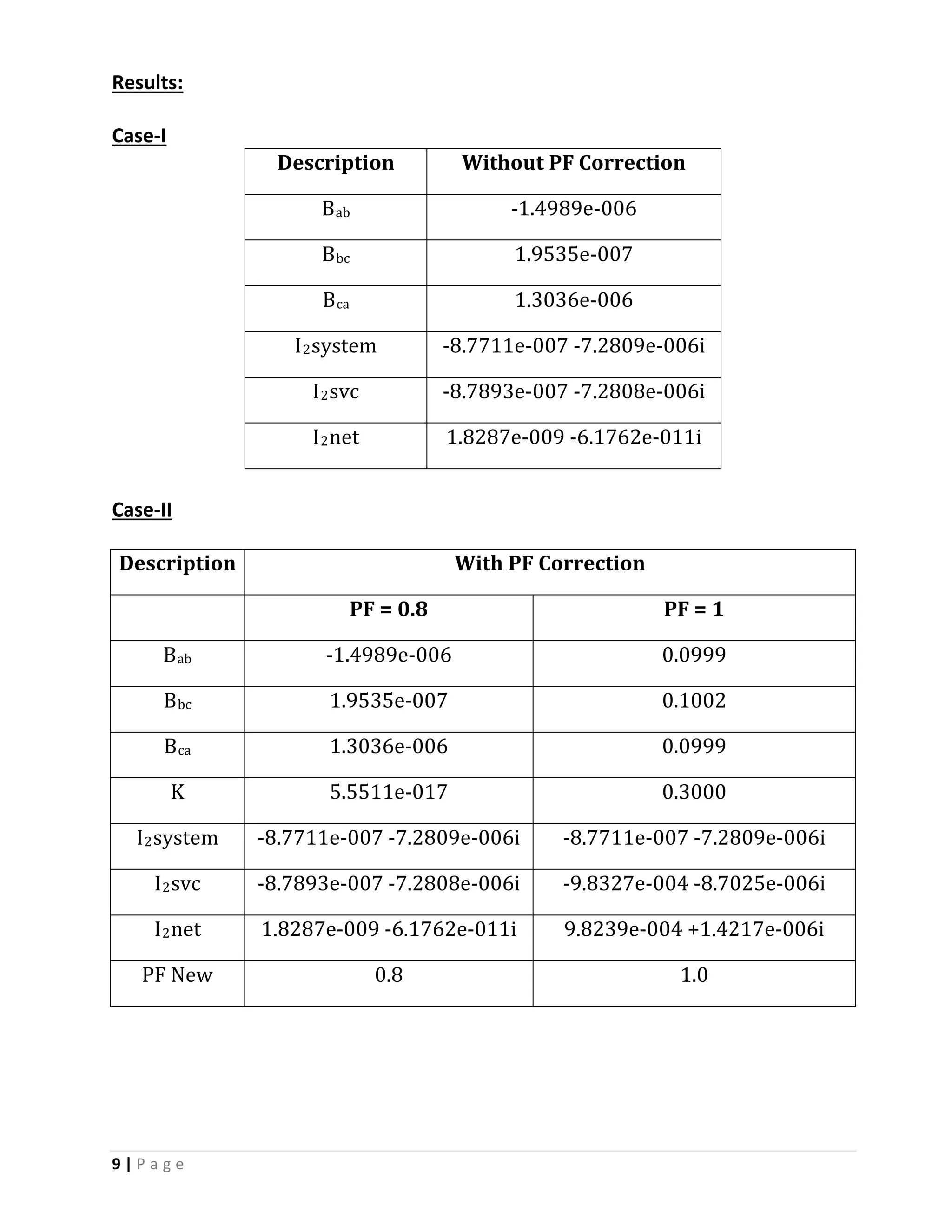
In both the cases it is observed that the net negative sequence flowing in the
system is reduced with introduction of SVC. It is observed that the SVC based FCTCR
reduce the negative sequence current with variable switching of Thyristor. It is also
important that SVC also supplies reactive power in case of power factor
improvement.
In this project we have learnt about operation of FC-TCR based Static VAR
Compensator and how to implement SVC for negative sequence current reduction
and power factor improvement. The approach followed is quite unique and novel
method which can be widely implemented to overcome the consequences of
negative sequence current in modern power system.
Learning outcome:
1) Thesis: The prevention of super synchronous resonance problem on the
turbine system of generator with staticvar compensator
References:
By Jen-hung chen
2) Negative sequence current reduction for generator turbine protection
Wei-jen lee, Tze-yee ho, member, Jih-phong liu, Yuin-hong liu, IEEE member](https://image.slidesharecdn.com/ee5374project2hardikparikh1001090431-160420210732/75/Design-of-a-3-phase-FC-TCR-Static-Var-Compensator-for-Power-factor-correction-and-Preventation-of-negative-sequence-current-12-2048.jpg)

This document describes a project to design a three-phase individual controlled fixed capacitor-thyristor controlled reactor (FC-TCR) static VAR compensator (SVC) to perform power factor correction and prevent negative sequence current. It includes an abstract discussing the issues with negative sequence current, an introduction to the FC-TCR SVC design, the design procedure and algorithm, results showing the SVC reduces negative sequence current both with and without power factor correction, the source code implementing the design, and a conclusion stating the SVC approach is effective and unique.


![Chapter 4 dc machine [autosaved]](https://cdn.slidesharecdn.com/ss_thumbnails/chapter4-dcmachineautosaved-140915220206-phpapp01-thumbnail.jpg?width=640&height=640&fit=bounds)


![Chapter4_Initiation_of_Sediment_Motion_v2[1].pptx](https://cdn.slidesharecdn.com/ss_thumbnails/chapter4initiationofsedimentmotionv21-251208223747-f94ef163-thumbnail.jpg?width=640&height=640&fit=bounds)


![Soundtoys Mac v5.5.5.0 Crack for MacOS Full Version [Latest] pptx](https://cdn.slidesharecdn.com/ss_thumbnails/softwareoverview-251207193711-91d8ae6b-thumbnail.jpg?width=640&height=640&fit=bounds)
![AnyTrans for iOS 8.9.14.20251127 With Crack for MacOS [Latest] pptx](https://cdn.slidesharecdn.com/ss_thumbnails/softwareoverview-251207190907-2316965f-thumbnail.jpg?width=640&height=640&fit=bounds)


![Wondershare Filmora 15.0.11 Crack for Mac Key Full Download [Latest] pptx](https://cdn.slidesharecdn.com/ss_thumbnails/software-251207184836-1d16ba16-thumbnail.jpg?width=640&height=640&fit=bounds)


