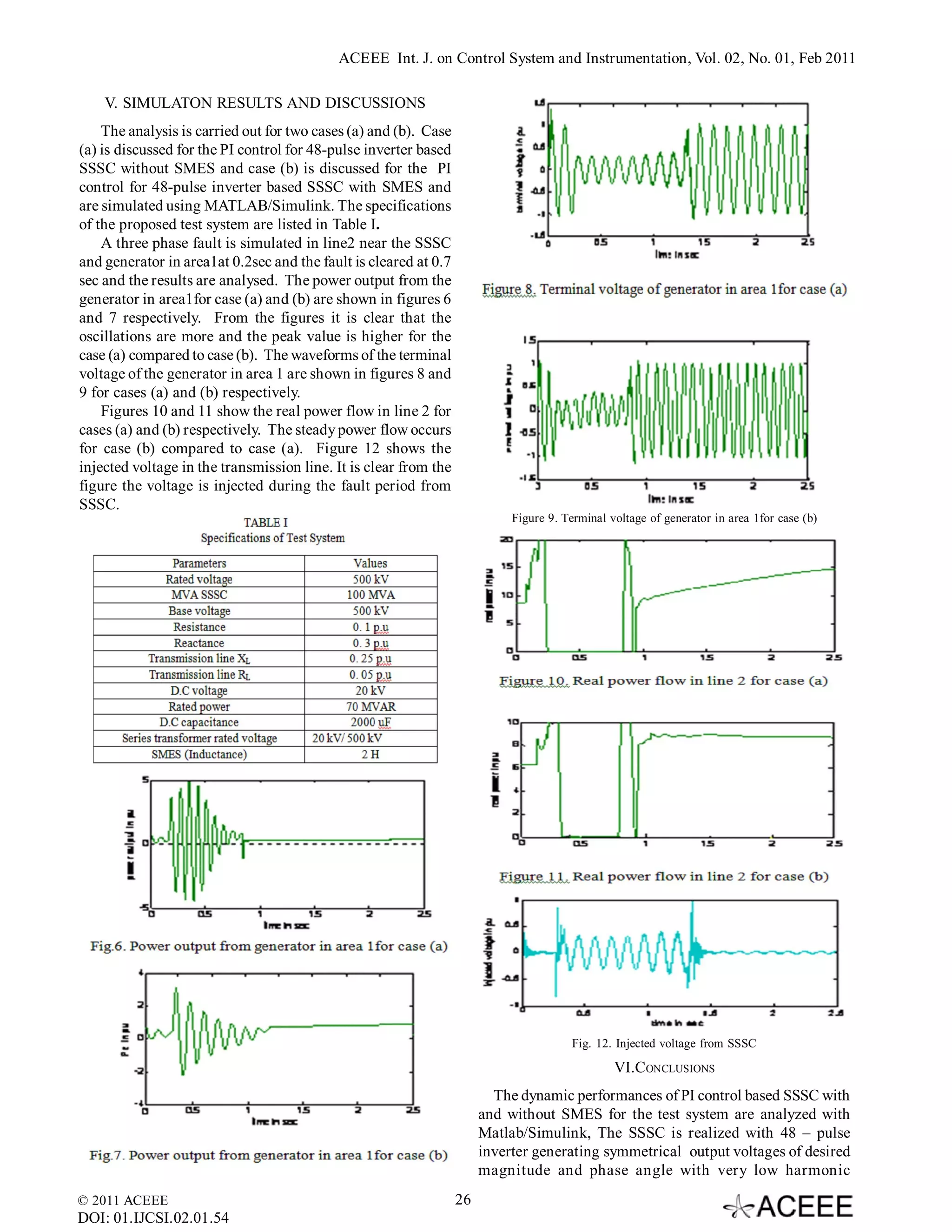
ACEEE Int. J. on Control System and Instrumentation, Vol. 02, No. 01, Feb 2011


 Static Synchronous Series Compensator (SSSC) with
 Superconducting Magnetic Energy Storage (SMES)
 for the Enhancement of Transient Stability in Multi-
                    Area System
                                              S. Padma#1, Dr. R. Lakshmipathi*2
                            #
                              Electrical and Electronics Engineering Department, Anna University,
                                    Sona College of Technology, Salem-5, Tamilnadu, India.
                            *
                              Electrical and Electronics Engineering Department, Anna University,
                                   St Peter’s Engineering College,Chennai, Tamilnadu, India.
                                                       1
                                                         swanisha@gmail.com
                                                  2
                                                    drrlakshmipathi@yahoo.com


Abstract— Static Synchronous Series Compensator (SSSC) has              the power flow, which uses FACTS controllers with energy
been designed with Superconducting Magnetic Energy Storage              storage. The switching power converter-based FACTS
(SMES) system. A closed loop control scheme has been                    controllers can carry this out. Among the different variants
proposed with PI controller and real and reactive powers are            of FACTS devices, Static Synchronous Series Compensator
taken as references. A 48 pulse voltage source inverter is              (SSSC) is proposed as the most adequate for the present
designed for the SSSC. Control scheme for the chopper circuit
                                                                        application. The DC inner bus of the SSSC allows
of SMES coil is also designed. A three area system is taken as
the test system and the operation of SSSC with SMES is
                                                                        incorporating a substantial amount of energy storage in order
analysed for various transient disturbances. Test results under         to enlarge the degrees of freedom of the SSSC device and
different disturbances and operating conditions show the                also to exchange active and reactive power with the utility
proposed SSSC with SMES is effective in damping out the                 grid. Based on a previous study of all energy storage
power system oscillations.                                              technologies currently available, the use of Superconducting
                                                                        Magnetic Energy Storage system (SMES) is proposed for
Keywords— SSSC, SMES, Transient stability, voltage source               the considered application [7]-[9].
inverter, closed loop control                                              This paper proposes a detailed model of an SSSC with
                                                                        and without SMES, and a PI control algorithm for this
                         I.INTRODUCTION                                 combined system to carry out the power flow control of the
    Today’s modern interconnected power system is highly                electric system. This paper also lays the foundations for an
complex in nature and the electrical power consumptions                 increased operational flexibility by integrating energy storage
and transactions have rapidly increased. Under these                    devices with other power converter-based FACTS
circumstances the keen issue is how to expand the existing              controllers’ structures. The SMES coil is connected to the
transmission equipment to meet the growth of demands in                 VSI through a dc–dc chopper. It controls dc current and
an economical way. Maintaining stability of such an                     voltage levels by converting the inverter dc output voltage
interconnected power system has become a cumbersome                     to the adjustable voltage required across the SMES coil
task. As a countermeasure against these problems, the                   terminal. A two-level three-phase dc–dc chopper used in the
Flexible AC Transmission System (FACTS) devices were                    simulation has been modeled and controlled according to
proposed and the prototypes have been developed. The                    [15], [16].
applications of FACTS devices to improve system damping                    Details on operation, analysis, control strategy and
against both dynamic and transient stability have been                  simulation results for SSSC with and without SMES are
reported in the literature [1]-[2].                                     presented in the subsequent sections.
    Simultaneous real and reactive power control has also
been proposed in the literature [3]-[5]. In this sense, research                         II. OPERATION   OF SSSC WITH SMES

in this field has been lately extended with the aim of                       SSSC is a voltage sourced converter based series
incorporating power electronic devices into electric power              compensator. The compensation works by increasing the
systems - FACTS devices. Presently, these devices are a                 voltage across the impedance of the given physical line,
viable alternative as they allow controlling voltages and               which in turn increases the corresponding line current and
currents of appropriate magnitude for electric power systems            the transmitted power. For normal capacitive compensation,
at an increasingly lower cost [6]. However, a comparable                the output voltage lags the line current by 90o. With voltage
field of knowledge on FACTS/ESS control is quite limited.               source inverters the output voltage can be reversed by simple
Therefore, in this work a methodology is proposed to control            control action to make it lead or lag the line current by 90o.

© 2011 ACEEE                                                       23
DOI: 01.IJCSI.02.01.54
ACEEE Int. J. on Control System and Instrumentation, Vol. 02, No. 01, Feb 2011

The single line diagram of the multi-machine system used             Where,
for the simulation study is shown in Fig. 1.


                                                                     and
                                                                     m = 48r±i, r=0, 1, 2,. .
                                                                     i =1, for positive sequence harmonics and i=-1, for negative
                                                                     sequence harmonics
                                                                          The voltages Vbc48 and Vca48 exhibit a similar pattern
                                                                     except phase shifted by 120o and 240o respectively. Similarly,
                                                                     the phase voltages Vbn48 and Vcn48 are also phase shifted by
                                                                     120o and 240o respectively.

                                                                                  III.DECOUPED   CONTROL SCHEME FOR SSSC

                                                                               The main function of the SSSC is to dynamically
                                                                     control the power flow over the transmission line. The
         If Vs and Vr are the sending end and receiving end
                                                                     control scheme proposed earlier [3] is based on the line
voltages, then the real and reactive power (P & Q) flow at
                                                                     impedance control mode in which the SSSC compensating
the receiving end can be expressed as
                                                                     voltage is derived by multiplying the current amplitude with
                                                                     the desired compensating reactance Xqref. Since it is difficult
                                                                     to predict Xqref under varying network contingencies, in the
                                                                     proposed scheme, the controller is modified as shown in fig.
                                                                     2 to operate the SSSC in the automatic power flow control
                                                                     mode [4]. In this mode, the reference inputs to the controller
                                                                     are P ref and Q ref, which are to be maintained in the
         The SSSC introduces a virtual compensating reac-            transmission line despite system changes. The instantaneous
tance, Xq (both inductive and capacitive), in series with the        power is obtained in terms of d-q quantities as,
transmission line inductive reactance XL. Now the expres-
sions for the real and reactive powers are,


                                                                     The line current Iabc and the line voltage Vabc are sensed at
                                                                     the point B2 on the transmission line of Fig. 1 and are con-
                                                                     verted into d-q components. The desired current references
where, Xeff is the effective reactance of the transmission           Idref and Iqref are compared with actual current components Id
line, including the emulated variable reactance inserted             and Iq respectively and the error signals are processed in the
through the injected voltage source supplied by the SSSC.            neural controller. Initially PI controller is designed [5]-[6].
Xq is negative when the SSSC is operated in the inductive            Based on the controller parameters, the required small dis-
mode and positive when the SSSC is operated in the
                                                                     placement angle  to control the angle of the injected volt-
capacitive mode.
         With 48 - pulse VSI, AC filters are not required.           age with respect to the line current has been derived. A Phase
The inverter described is harmonic neutralized. The                  Locked Loop (PLL) is used to determine the instantaneous
instantaneous values of the phase-to-phase voltage and the           angle  of the three-phase line voltage Vabc. The current Iabc
phase to neutral voltage of the 48 pulse inverter output             is decoupled into Id and Iq of the three phase line currents are
voltage are expressed as Eq. (5) and (6)
                                                                     used to determine the angle    ir relative to the voltage Vabc.
                                                                     Depending upon the instantaneous reactive power with re-

                                                                     spect to the desired value either ( 2 ) is added (inductive)

                                                                     or subtracted (capacitive) with  . Thus, the required phase
                                                                     angle is
© 2011 ACEEE                                                    24
DOI: 01.IJCSI.02.01.54
ACEEE Int. J. on Control System and Instrumentation, Vol. 02, No. 01, Feb 2011

                                                                     For generating the gating pulses for VSI and the DC-DC
                                                                     chopper, internal control block is designed. Fig. 4 shows
                                                                     the block diagram for the estimation of duty cycle for pro-
                                                                     posed system [14]. The control scheme includes the
                                                                     decoupled control for the real and reactive power. The two
                                                                     independent reference signals are the reactive current and
                                                                     the active current. From these reference signals the ampli-
                                                                     tude and phase ratings of the voltage at the VSI is deter-
                                                                     mined. The duty cycle D is estimated from the active power
                                                                     ratings that the SSSC should inject from the voltage at the
                                                                     DC bus and from the current stored into the SMES coil. This
                                                                     estimated value of Dest is adjusted through a closed loop con-
                                                                     trol whose function is eliminating the voltage error between
                                                                     the calculated and the real voltage ratings at the DC bus.


            IV.CHOPPER CONTROL FOR SMES
   An electronic interface known as chopper is needed
between the energy source and the VSI. For VSI the energy
source compensates the capacitor charge through the
electronic interface and maintains the required capacitor
voltage. Two-quadrant n-phase DC-DC converter as shown
in Fig. 3 is adopted as interface. Here ‘n’ is related to the
maximum current driven by the superconducting device. The
DC-DC chopper solves the problems of the high power rating
requirements imposed by the superconducting coil to the
SSSC.


© 2011 ACEEE                                                    25
DOI: 01.IJCSI.02.01.54
ACEEE Int. J. on Control System and Instrumentation, Vol. 02, No. 01, Feb 2011

    V. SIMULATON RESULTS AND DISCUSSIONS
    The analysis is carried out for two cases (a) and (b). Case
(a) is discussed for the PI control for 48-pulse inverter based
SSSC without SMES and case (b) is discussed for the PI
control for 48-pulse inverter based SSSC with SMES and
are simulated using MATLAB/Simulink. The specifications
of the proposed test system are listed in Table I.
    A three phase fault is simulated in line2 near the SSSC
and generator in area1at 0.2sec and the fault is cleared at 0.7
sec and the results are analysed. The power output from the
generator in area1for case (a) and (b) are shown in figures 6
and 7 respectively. From the figures it is clear that the
oscillations are more and the peak value is higher for the
case (a) compared to case (b). The waveforms of the terminal
voltage of the generator in area 1 are shown in figures 8 and
9 for cases (a) and (b) respectively.
    Figures 10 and 11 show the real power flow in line 2 for
cases (a) and (b) respectively. The steady power flow occurs
for case (b) compared to case (a). Figure 12 shows the
injected voltage in the transmission line. It is clear from the
figure the voltage is injected during the fault period from
SSSC.
                                                                            Figure 9. Terminal voltage of generator in area 1for case (b)


                                                                                        Fig. 12. Injected voltage from SSSC

                                                                                                VI.CONCLUSIONS
                                                                         The dynamic performances of PI control based SSSC with
                                                                       and without SMES for the test system are analyzed with
                                                                       Matlab/Simulink, The SSSC is realized with 48 – pulse
                                                                       inverter generating symmetrical output voltages of desired
                                                                       magnitude and phase angle with very low harmonic
© 2011 ACEEE                                                      26
DOI: 01.IJCSI.02.01.54
ACEEE Int. J. on Control System and Instrumentation, Vol. 02, No. 01, Feb 2011


components. In this paper SMES with two quadrant chopper                  [7]    Molina, M.G. and P. E. Mercado, “Modeling of a Static
control play an important role in real power exchange. A PI                      Synchronous Compensator with Superconducting
control based SSSC with and without SMES has been                                Magnetic Energy Storage for Applications on Frequency
developed to improve transient stability performance of the                      Control”, Proc. VIII SEPOPE, Brasilia, Brazil, 2002, pp.
                                                                                 17-22.
power system. It is inferred from the results that the SSSC
                                                                          [8]    Molina, M.G. and P. E. Mercado, “New Energy Storage
with SMES is very efficient in transient stability enhancement                   Devices for Applications on Frequency Control of the
and effective in damping the power oscillations and to                           Power System using FACTS Controllers,” Proc. X
maintain power flow through transmission lines after the                         ERLAC, Iguazú, Argentina, 14.6, 2003, 1-6.
disturbances.                                                             [9]    Molina, M.G. and P. E. Mercado, “Evaluation of Energy
                                                                                 Storage Systems for application in the Frequency
                       ACKNOWLEDGMENT                                            Control”, Proc. 6th COBEP, Florianópolis, Brazil, 2001,
                                                                                 pp. 479-484.
  We sincerely thank the Management, Secretary and                        [10]   Anil. C. Pradhan and P.W. Lehn, “Frequency domain
Principal of Sona College of Technology, Salem for their                         analysis of the static synchronous series compensator,”
complete support in doing this research work.                                    IEEE Transactions on Power Delivery, vol. 21(1),
                                                                                 January 2006, pp. 440-450.
                          REFERENCES                                      [11]   B. Geethalakshmi and P. Dananjayan, “Investigations of
                                                                                 Performance of UPFC without DC link capacitor,”
    [1]   S. S. Choi, F. Jiang and G. Shrestha, “Suppression of
                                                                                 Electric Power System Research, vol. 78, Issue 4, pp.
          transmission system oscillations by thyristor controlled               736-746, April 2007.
          series compensation”, IEE Proc., Vol.GTD-143, No.1,             [12]   V.S.C. Raviraj and P.C. Sen, “Comparative study of
          1996, pp 7-12.                                                         proportional-integral, sliding mode, and FLC for power
    [2]   M.W. Tsang and D. Sutanto, “Power System Stabiliser                    converters,” IEEE Transactions on Industry Applications,
          using Energy Storage”, 0-7803-5935-6/00 2000, IEEE                     vol. 33 no. 2, March/April 1997, pp. 518–524.
    [3]   B. Bhargava and G. Dishaw, “Appllication of an energy           [13]   Bruce S. Rigby and R. G. Harley, “An improved control
          source power system stabilizer on the 10MW battery                     scheme for a series capacitive reactance compensator
          energy storage system at Chino Substation”, IEEE Trans.,               based on a voltage-source inverter,” IEEE Trans. Industry
          Vol.PS-13, No.1, 1998, pp. 145-151.                                    Applications, vol. 34, no. 2, Mar./Apr.1998, pp. 355-363.
    [4]   S. Macdonald, L. Kovalsky, “Benefit of Static                   [14]   Lasseter R.H. and S. G. Lalali, “Dynamic Response of
          Compensator (STATCOM) plus Superconducting                             Power Conditioning Systems for Superconductive
          Magnetic Energy Storage (SMES) in the Transmission                     Magnetic Energy Storage,” IEEE Trans. On Energy
          network”, 2001, Energy Storage Association Meeting                     Conversion, 6, 3, 1991, pp. 388-393.
          Chattanooga, Tennessee.                                         [15]   A. B. Arsoy, Z. Wang, Y. Liu, and P. F. Ribeiro,
    [5]   Z. Yang, C. Shen, L. Zhang, M.L. Crow, S. Atcitty,                     “Electromagnetic transient interaction of a SMES coil
          “Integration of a StatCom and Battery Energy Storage.                  and the power electronics interface,” in Proc. 16th Annual
    [6]   Hingorani, N.G., “Role of FACTS in a Deregulated                       VPEC Seminar, vol. 16, Sep. 13–15, 1998, pp. 361–367.
          Market,” Proc. IEEE Power Engineering Society Winter            [16]   M. Steurer and W. Hribernik, “Frequency response
          Meeting, Seattle, WA, USA, 2006, pp. 1-6.                              characteristics of a 100 MJ SMES coil–Measurements
                                                                                 and model refinement,” IEEE Trans.Appl. Superconduct.,
                                                                                 pt. 2, vol. 15, no. 2, pp. 1887–1890, Jun. 2005.


© 2011 ACEEE                                                         27
DOI: 01.IJCSI.02.01.54

Static Synchronous Series Compensator (SSSC) with Superconducting Magnetic Energy Storage (SMES) for the Enhancement of Transient Stability in Multi- Area System

  • 1.
    ACEEE Int. J.on Control System and Instrumentation, Vol. 02, No. 01, Feb 2011 Static Synchronous Series Compensator (SSSC) with Superconducting Magnetic Energy Storage (SMES) for the Enhancement of Transient Stability in Multi- Area System S. Padma#1, Dr. R. Lakshmipathi*2 # Electrical and Electronics Engineering Department, Anna University, Sona College of Technology, Salem-5, Tamilnadu, India. * Electrical and Electronics Engineering Department, Anna University, St Peter’s Engineering College,Chennai, Tamilnadu, India. 1 swanisha@gmail.com 2 drrlakshmipathi@yahoo.com Abstract— Static Synchronous Series Compensator (SSSC) has the power flow, which uses FACTS controllers with energy been designed with Superconducting Magnetic Energy Storage storage. The switching power converter-based FACTS (SMES) system. A closed loop control scheme has been controllers can carry this out. Among the different variants proposed with PI controller and real and reactive powers are of FACTS devices, Static Synchronous Series Compensator taken as references. A 48 pulse voltage source inverter is (SSSC) is proposed as the most adequate for the present designed for the SSSC. Control scheme for the chopper circuit application. The DC inner bus of the SSSC allows of SMES coil is also designed. A three area system is taken as the test system and the operation of SSSC with SMES is incorporating a substantial amount of energy storage in order analysed for various transient disturbances. Test results under to enlarge the degrees of freedom of the SSSC device and different disturbances and operating conditions show the also to exchange active and reactive power with the utility proposed SSSC with SMES is effective in damping out the grid. Based on a previous study of all energy storage power system oscillations. technologies currently available, the use of Superconducting Magnetic Energy Storage system (SMES) is proposed for Keywords— SSSC, SMES, Transient stability, voltage source the considered application [7]-[9]. inverter, closed loop control This paper proposes a detailed model of an SSSC with and without SMES, and a PI control algorithm for this I.INTRODUCTION combined system to carry out the power flow control of the Today’s modern interconnected power system is highly electric system. This paper also lays the foundations for an complex in nature and the electrical power consumptions increased operational flexibility by integrating energy storage and transactions have rapidly increased. Under these devices with other power converter-based FACTS circumstances the keen issue is how to expand the existing controllers’ structures. The SMES coil is connected to the transmission equipment to meet the growth of demands in VSI through a dc–dc chopper. It controls dc current and an economical way. Maintaining stability of such an voltage levels by converting the inverter dc output voltage interconnected power system has become a cumbersome to the adjustable voltage required across the SMES coil task. As a countermeasure against these problems, the terminal. A two-level three-phase dc–dc chopper used in the Flexible AC Transmission System (FACTS) devices were simulation has been modeled and controlled according to proposed and the prototypes have been developed. The [15], [16]. applications of FACTS devices to improve system damping Details on operation, analysis, control strategy and against both dynamic and transient stability have been simulation results for SSSC with and without SMES are reported in the literature [1]-[2]. presented in the subsequent sections. Simultaneous real and reactive power control has also been proposed in the literature [3]-[5]. In this sense, research II. OPERATION OF SSSC WITH SMES in this field has been lately extended with the aim of SSSC is a voltage sourced converter based series incorporating power electronic devices into electric power compensator. The compensation works by increasing the systems - FACTS devices. Presently, these devices are a voltage across the impedance of the given physical line, viable alternative as they allow controlling voltages and which in turn increases the corresponding line current and currents of appropriate magnitude for electric power systems the transmitted power. For normal capacitive compensation, at an increasingly lower cost [6]. However, a comparable the output voltage lags the line current by 90o. With voltage field of knowledge on FACTS/ESS control is quite limited. source inverters the output voltage can be reversed by simple Therefore, in this work a methodology is proposed to control control action to make it lead or lag the line current by 90o. © 2011 ACEEE 23 DOI: 01.IJCSI.02.01.54
  • 2.
    ACEEE Int. J.on Control System and Instrumentation, Vol. 02, No. 01, Feb 2011 The single line diagram of the multi-machine system used Where, for the simulation study is shown in Fig. 1. and m = 48r±i, r=0, 1, 2,. . i =1, for positive sequence harmonics and i=-1, for negative sequence harmonics The voltages Vbc48 and Vca48 exhibit a similar pattern except phase shifted by 120o and 240o respectively. Similarly, the phase voltages Vbn48 and Vcn48 are also phase shifted by 120o and 240o respectively. III.DECOUPED CONTROL SCHEME FOR SSSC The main function of the SSSC is to dynamically control the power flow over the transmission line. The If Vs and Vr are the sending end and receiving end control scheme proposed earlier [3] is based on the line voltages, then the real and reactive power (P & Q) flow at impedance control mode in which the SSSC compensating the receiving end can be expressed as voltage is derived by multiplying the current amplitude with the desired compensating reactance Xqref. Since it is difficult to predict Xqref under varying network contingencies, in the proposed scheme, the controller is modified as shown in fig. 2 to operate the SSSC in the automatic power flow control mode [4]. In this mode, the reference inputs to the controller are P ref and Q ref, which are to be maintained in the The SSSC introduces a virtual compensating reac- transmission line despite system changes. The instantaneous tance, Xq (both inductive and capacitive), in series with the power is obtained in terms of d-q quantities as, transmission line inductive reactance XL. Now the expres- sions for the real and reactive powers are, The line current Iabc and the line voltage Vabc are sensed at the point B2 on the transmission line of Fig. 1 and are con- verted into d-q components. The desired current references where, Xeff is the effective reactance of the transmission Idref and Iqref are compared with actual current components Id line, including the emulated variable reactance inserted and Iq respectively and the error signals are processed in the through the injected voltage source supplied by the SSSC. neural controller. Initially PI controller is designed [5]-[6]. Xq is negative when the SSSC is operated in the inductive Based on the controller parameters, the required small dis- mode and positive when the SSSC is operated in the placement angle  to control the angle of the injected volt- capacitive mode. With 48 - pulse VSI, AC filters are not required. age with respect to the line current has been derived. A Phase The inverter described is harmonic neutralized. The Locked Loop (PLL) is used to determine the instantaneous instantaneous values of the phase-to-phase voltage and the angle  of the three-phase line voltage Vabc. The current Iabc phase to neutral voltage of the 48 pulse inverter output is decoupled into Id and Iq of the three phase line currents are voltage are expressed as Eq. (5) and (6) used to determine the angle  ir relative to the voltage Vabc. Depending upon the instantaneous reactive power with re- spect to the desired value either ( 2 ) is added (inductive) or subtracted (capacitive) with  . Thus, the required phase angle is © 2011 ACEEE 24 DOI: 01.IJCSI.02.01.54
  • 3.
    ACEEE Int. J.on Control System and Instrumentation, Vol. 02, No. 01, Feb 2011 For generating the gating pulses for VSI and the DC-DC chopper, internal control block is designed. Fig. 4 shows the block diagram for the estimation of duty cycle for pro- posed system [14]. The control scheme includes the decoupled control for the real and reactive power. The two independent reference signals are the reactive current and the active current. From these reference signals the ampli- tude and phase ratings of the voltage at the VSI is deter- mined. The duty cycle D is estimated from the active power ratings that the SSSC should inject from the voltage at the DC bus and from the current stored into the SMES coil. This estimated value of Dest is adjusted through a closed loop con- trol whose function is eliminating the voltage error between the calculated and the real voltage ratings at the DC bus. IV.CHOPPER CONTROL FOR SMES An electronic interface known as chopper is needed between the energy source and the VSI. For VSI the energy source compensates the capacitor charge through the electronic interface and maintains the required capacitor voltage. Two-quadrant n-phase DC-DC converter as shown in Fig. 3 is adopted as interface. Here ‘n’ is related to the maximum current driven by the superconducting device. The DC-DC chopper solves the problems of the high power rating requirements imposed by the superconducting coil to the SSSC. © 2011 ACEEE 25 DOI: 01.IJCSI.02.01.54
  • 4.
    ACEEE Int. J.on Control System and Instrumentation, Vol. 02, No. 01, Feb 2011 V. SIMULATON RESULTS AND DISCUSSIONS The analysis is carried out for two cases (a) and (b). Case (a) is discussed for the PI control for 48-pulse inverter based SSSC without SMES and case (b) is discussed for the PI control for 48-pulse inverter based SSSC with SMES and are simulated using MATLAB/Simulink. The specifications of the proposed test system are listed in Table I. A three phase fault is simulated in line2 near the SSSC and generator in area1at 0.2sec and the fault is cleared at 0.7 sec and the results are analysed. The power output from the generator in area1for case (a) and (b) are shown in figures 6 and 7 respectively. From the figures it is clear that the oscillations are more and the peak value is higher for the case (a) compared to case (b). The waveforms of the terminal voltage of the generator in area 1 are shown in figures 8 and 9 for cases (a) and (b) respectively. Figures 10 and 11 show the real power flow in line 2 for cases (a) and (b) respectively. The steady power flow occurs for case (b) compared to case (a). Figure 12 shows the injected voltage in the transmission line. It is clear from the figure the voltage is injected during the fault period from SSSC. Figure 9. Terminal voltage of generator in area 1for case (b) Fig. 12. Injected voltage from SSSC VI.CONCLUSIONS The dynamic performances of PI control based SSSC with and without SMES for the test system are analyzed with Matlab/Simulink, The SSSC is realized with 48 – pulse inverter generating symmetrical output voltages of desired magnitude and phase angle with very low harmonic © 2011 ACEEE 26 DOI: 01.IJCSI.02.01.54
  • 5.
    ACEEE Int. J.on Control System and Instrumentation, Vol. 02, No. 01, Feb 2011 components. In this paper SMES with two quadrant chopper [7] Molina, M.G. and P. E. Mercado, “Modeling of a Static control play an important role in real power exchange. A PI Synchronous Compensator with Superconducting control based SSSC with and without SMES has been Magnetic Energy Storage for Applications on Frequency developed to improve transient stability performance of the Control”, Proc. VIII SEPOPE, Brasilia, Brazil, 2002, pp. 17-22. power system. It is inferred from the results that the SSSC [8] Molina, M.G. and P. E. Mercado, “New Energy Storage with SMES is very efficient in transient stability enhancement Devices for Applications on Frequency Control of the and effective in damping the power oscillations and to Power System using FACTS Controllers,” Proc. X maintain power flow through transmission lines after the ERLAC, Iguazú, Argentina, 14.6, 2003, 1-6. disturbances. [9] Molina, M.G. and P. E. Mercado, “Evaluation of Energy Storage Systems for application in the Frequency ACKNOWLEDGMENT Control”, Proc. 6th COBEP, Florianópolis, Brazil, 2001, pp. 479-484. We sincerely thank the Management, Secretary and [10] Anil. C. Pradhan and P.W. Lehn, “Frequency domain Principal of Sona College of Technology, Salem for their analysis of the static synchronous series compensator,” complete support in doing this research work. IEEE Transactions on Power Delivery, vol. 21(1), January 2006, pp. 440-450. REFERENCES [11] B. Geethalakshmi and P. Dananjayan, “Investigations of Performance of UPFC without DC link capacitor,” [1] S. S. Choi, F. Jiang and G. Shrestha, “Suppression of Electric Power System Research, vol. 78, Issue 4, pp. transmission system oscillations by thyristor controlled 736-746, April 2007. series compensation”, IEE Proc., Vol.GTD-143, No.1, [12] V.S.C. Raviraj and P.C. Sen, “Comparative study of 1996, pp 7-12. proportional-integral, sliding mode, and FLC for power [2] M.W. Tsang and D. Sutanto, “Power System Stabiliser converters,” IEEE Transactions on Industry Applications, using Energy Storage”, 0-7803-5935-6/00 2000, IEEE vol. 33 no. 2, March/April 1997, pp. 518–524. [3] B. Bhargava and G. Dishaw, “Appllication of an energy [13] Bruce S. Rigby and R. G. Harley, “An improved control source power system stabilizer on the 10MW battery scheme for a series capacitive reactance compensator energy storage system at Chino Substation”, IEEE Trans., based on a voltage-source inverter,” IEEE Trans. Industry Vol.PS-13, No.1, 1998, pp. 145-151. Applications, vol. 34, no. 2, Mar./Apr.1998, pp. 355-363. [4] S. Macdonald, L. Kovalsky, “Benefit of Static [14] Lasseter R.H. and S. G. Lalali, “Dynamic Response of Compensator (STATCOM) plus Superconducting Power Conditioning Systems for Superconductive Magnetic Energy Storage (SMES) in the Transmission Magnetic Energy Storage,” IEEE Trans. On Energy network”, 2001, Energy Storage Association Meeting Conversion, 6, 3, 1991, pp. 388-393. Chattanooga, Tennessee. [15] A. B. Arsoy, Z. Wang, Y. Liu, and P. F. Ribeiro, [5] Z. Yang, C. Shen, L. Zhang, M.L. Crow, S. Atcitty, “Electromagnetic transient interaction of a SMES coil “Integration of a StatCom and Battery Energy Storage. and the power electronics interface,” in Proc. 16th Annual [6] Hingorani, N.G., “Role of FACTS in a Deregulated VPEC Seminar, vol. 16, Sep. 13–15, 1998, pp. 361–367. Market,” Proc. IEEE Power Engineering Society Winter [16] M. Steurer and W. Hribernik, “Frequency response Meeting, Seattle, WA, USA, 2006, pp. 1-6. characteristics of a 100 MJ SMES coil–Measurements and model refinement,” IEEE Trans.Appl. Superconduct., pt. 2, vol. 15, no. 2, pp. 1887–1890, Jun. 2005. © 2011 ACEEE 27 DOI: 01.IJCSI.02.01.54