Downloaded 544 times
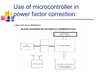
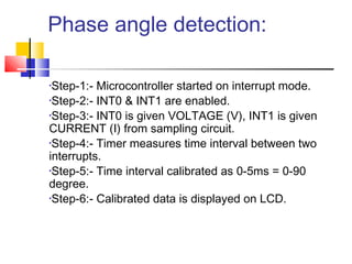


This document describes an automatic power factor correction system using a microcontroller. It measures the phase difference between the voltage and current waves using interrupts from a zero crossing detector. The microcontroller then calculates the power factor and switches capacitor banks as needed in steps to improve the power factor. This provides accurate and fast power factor correction to increase the efficiency of electrical systems.