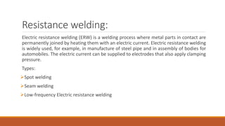
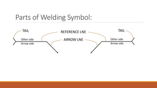
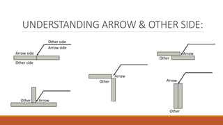
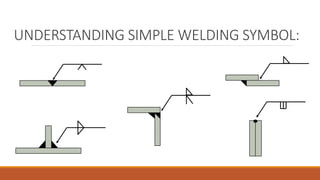
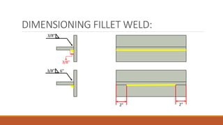
The document provides an overview of welding processes, including types of welding such as gas, arc, and resistance welding. It explains the principles and applications of various welding techniques, the importance of choosing the right welding process based on several factors, and offers guidance on weld symbols and standards. Additionally, it highlights best practices for fillet welding standards and provides insights on evaluating appropriate welding methods for specific materials and conditions.


![Yared welding technology[1]](https://cdn.slidesharecdn.com/ss_thumbnails/yaredweldingtechnology1-210212083835-thumbnail.jpg?width=640&height=640&fit=bounds)
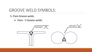
![Yared welding technology[1]](https://cdn.slidesharecdn.com/ss_thumbnails/yaredweldingtechnology1-210212083943-thumbnail.jpg?width=640&height=640&fit=bounds)


