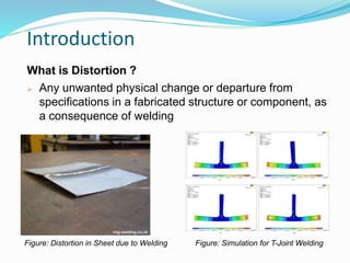
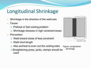
Prepared by - Urvisha Kharva
Department of Metallurgical & Material Engineering
MSU Vadodara
CONTENTS
 Introduction: Distortion in Welding
 Significance of Material Properties
 Influence of Welding Processes & Procedures
 Types of Welding Distortions
 Welding Suitability Index based on Distortion
 Measurement of Distortion
 Control of Distortion in Weldments
 Correction of Distorted Weldments
 Future Scope in Measuring Weld Distortions
2
Introduction
What is Distortion ?
 Any unwanted physical change or departure from
specifications in a fabricated structure or component, as
a consequence of welding
Figure: Distortion in Sheet due to Welding Figure: Simulation for T-Joint Welding
3
Introduction
 Main Causes of Distortion
 Non-Uniform Expansion and Contraction, i.e. Shrinkage
due to plastic thermal strain, of the weld metal and base
metal during the heating and cooling cycle
 Internal stresses formed in base metal due to removing
restraints given to welds by fixed components surrounding it
So, both Welding processes & procedures and Material
properties affect the extent of distortion.
 Effects of Distortion:
 Complicate further fabrication
 Reduced application of the structure
 High cost of rectifying deformations
4
Significance of Material Properties
5
Properties of Materials Effects
(Requirements for Less
Distortion)
Coefficient of Thermal
Expansion (α)
Lower coefficient of thermal expansion
Thermal Conductivity (K) High Thermal Conductivity leads to low
thermal gradients
Yield Strength (ơy) Lower the yield strength of the parent
material, lower the residual stresses causing
distortions
Modulus of Elasticity (E) Higher the Modulus of Elasticity (stiffness) of
the parent material
Influence of Welding Processes & Procedures
6
Factors affecting Volume of
Heated Metal
Effects (Requirements for less
distortion)
Welding Processes •Concentrated heat source
•High welding speeds
•Deep penetration
•Single Pass Welding, Least Weld runs
Amount of Weld Metal Minimum amount of weld metal
Welding Speed Maximum Welding speed Minimizes heat
spread and built-up, Solidification of weld
metal should be controlled
Edge Preparation and Fit- up Uniform Edge Preparations to allow
consistent shrinkage along the joint, Close
Fit-Ups
Welding Procedure Mechanised, Single Pass, High Speed
Welds
7
TYPES OF
WELDING
DISTORTIO
NS
Longitudinal
Shrinkage
Transverse
Shrinkage
Angular
Distortion
Longitudin
al
Distortions/
Bowing or
Bending
Rotational
Distortion
Buckling
and
Twisting
Types of
distortion
Transverse
Shrinkage
8
Schematic View of Distortions in Welding
Longitudinal Shrinkage
9
 Shrinkage in the direction of the weld axis
 Cause:
 Preheat or fast cooling problem
 Shrinkage stresses in high constraint areas
 Prevention:
 Weld toward areas of less constraint
 Weld short length
 Also preheat to even out the cooling rates
 Straightening press, jacks, clamps should be
used
Figure: Longitudinal
Shrinkage
Longitudinal Shrinkage
10
 Butt Welds
• ẟL= longitudinal shrinkage, mm
• I = welding current, amps
• T = length of the weld, mm
• t=plate thickness, mm
Figure: Butt Joint
Transverse Shrinkage
11
 Shrinkage running into or inside a weld, transverse to the weld axis
direction
 Cause: Weld metal hardness problem,
Constraints applied to weld-joints
Figure: Transverse
Shrinkage
 Butt Welds :
 ẟt = transverse Shrinkage
 ∆w = Cross-sectional area of weld,
mm2
 t = plate thicknes, mm
Figure: Butt Joint
Longitudinal Vs Transverse Shrinkage
13
Longitudinal Shrinkage Transverse Shrinkage
Butt
Welds
• 3mm per 3m of weld •1.5 to 3mm per weld for 60°
V joint, depending on number
of runs
• Amount of transverse shrinkage in a butt weld is much more (i.e.
1000th times of the weld length) than the longitudinal shrinkage
Fillet
Welds
• 0.8mm per 3m of weld •0.8mm per weld where the
leg length does not exceed 3/4
plate thickness
• Increasing the leg length of fillet welds increases shrinkage
Angular Distortion
14
 Weld tends to be wider at the top than
the bottom, causing more solidification
shrinkage and thermal contraction
 For Double-V Edge Butt weld-joint, it
depends upon root face and root gap
 Fillet weld-joints, it depends upon
flange width, weld leg length and
flange thickness
 Depends Upon :
 Width and depth of fusion zone relative
to plate thickness
 Type of joint
 Weld pass sequence
 Thermo-mechanical material properties
 Heat input per unit length of weld,
distribution of heat source density
Figure: Angular Distortion in Butt Weld-
joint
Figure: Angular Distortion in Fillet Weld-
Joint
Angular Distortion
15
 Occurs at butt, lap, T, corner joints due to single-sided as well as
asymmetrical double-sided welding
 Prevention:
 Reducing volume of weld metal
 Using double-V joint and alternate welding
 Placing welds around neutral axis
 Presetting: By compensating the amount of distortion to occur in
welding
 Elastic pre-springing can reduce angular changes after restraint
is removed.
 Preheating and post weld treatment
Bowing or Longitudinal welding
16
Figure: Longitudinal Bending
 Weld line does not coincide with neutral axis of a weld
structure
 Longitudinal shrinkage of the weld metal induces bending
moments
 Amount of distortion depends on :
 Shrinkage moment
 Resistance of the member to bending
A = cross-sectional area of the weld,mm2
d = distance from C.G. to outermost layer,mm
L = length of the weld, mm
I = Moment of Inertia of the section, mm4
Rotational Distortion
17
 In this, sheets being butt welded either come closer to each other or
the distance between them is widened
 Depends upon:
 Thickness of parent material
 Temperature difference between a molten pool and the unheaten parent
material (difference in heat flow)
 Speed of Welding,
 Heat Source
Figure: Rotational Distortions
Rotational Distortion
18
Progressively welding
material at widely different
heat inputs
Expanding & Contracting Zones in
arc butt welding
Here, Manual welds are termed as slow welds, while
Automatic welds are termed as fast welds
Twisting Distortions
20
To satisfy the conditions of a member
that has outer edges longer than its
centreline the member must twist
 Twisting is the due to low torsional resistance on thin
materials
When a weld is made along the centre
of a member, the weld area tends to
shrink and become shorter
Buckling And Twisting
21
 Prevention:
 Minimize Shrinkage by decreasing volume of weld
metal and highest compatible speed
 Keep the length of the welded member as short as
practical
 Incorporate torsional resistances to twisting as much
feasible
Measurement of Distortion
24
 Distortion in the post weld cooled state is determined by
applying length and angular measuring techniques
 Transverse and Longitudinal Shrinkage are determined by
Measuring Tape
 Angular Shrinkage is measured on a measuring plate by
means of straight edge set agaisnt the component (as shown
in below figure)
Figure: Measuring Longitudinal
& Transverse Shrinkage
Figure: Measuring Angular Distortions
Measurement of Distortion
25
 Measuring Bending or Angular Distortion
Figure: Measuring Angular Distortions or
Bending
Figure: Measuring Angular Distortions
Figure: Measuring Bending
Measurement of Distortion
26
 Circumferential
measurements on spherical
and cylindrical shells are
performed by string wrapped
around the structure
immersi
 Vertically extended
components, e.g. Pillars,
supports and tank walls,
inclinations and deflections
are measured by means of
strings hanging exactly
vertically and tensioning
weight ng in water
Figure: Distortions in Circumferential
surfaces
Figure: Distortions in
vertically Extended
components
Measurement of Distortion
28
 Small Scale Distortions using a Stereoscopic
Video Imaging system
Figure: 3d deformation measurement using a stereoscopic video imaging
system
Control of Distortion
29
 Welding Residual stresses and Welding Distortion behave in
a contrary way
 Least root gap:
 As small as possible, but sufficient for goodpenetration
 Excessive gaps should be avoided
 Included angle should not exceed 60°
 For heavy sections, double-V preparation should bepreferred
Control of Distortion
 Tack Welding
 Sufficiently long tack welds
transmit shrinkage forces
 Tack weld length should be two-
three times the plate thickness
 Preheating, slag removal and further
defect removal methods are
employed to counter undesired
30
phenomenon due to tack w
 Narrow Groove Section in
Welding
 Least as possible to produce least
heat concentration
 U shape groove is preferable than
Vee shape
 Symmetrical weld groove reduces
angular shrinkage, but residual
stresses are increased
 Double-sided fillet weld is selected
31
 Direction of Welding :
 Away from the point of restraint and towards the point of maximum
freedom
 Weld Metal Deposited :
 No excess metal should be deposited
 Block Sequence and Cascade Sequence :
 Todeposit long welds of high thickness
 Layer deposited until the effective throat thickness is achieved
Figure: Block
Sequence
Figure: Cascade
Sequence
Control of Distortion
32
 Welding Sequnce :
For large surface area consisting of several
plates, transverse seams should be welded first
followed by longitudinal seams
In welding I- or H- beam joints within each
web plate and flange are to welded first,
followed by butt joints between web plates
and flanges of a beam
Figure: Welding Sequence
for large plates
Figure: Welding Sequence for I or H Beam
Control of Distortion
34
 Back- Step Welding Sequence :
 Measure to counteract the wedge shaped-opening and closing(rotational
distortion)
 Reduces transverse and longitudinal shrinkage
 Used widely in fabrication of large structures, such as ships, storage tanks
Figure: Back-Step Welding Sequence
Control of Distortion
35
 Counter or Opposing Set-up
Figure: Warpage in a T-beam and
Suggested Counter setup
Figure: Counter Set-up for Angular Distortion
Control of Distortion
Correction of Distorted Weldments
37
 If a weldment warps despite the precautions taken, there are
ways and means of correcting the defect using one of the
following two methods:
Methods for Correction of
Distorted Weldments
Mechanical
Methods
Presses, Jack Screws
, Straightening Rolls,
Sledges, Special
Fixtures
Thermal
Methods
Oxy-
acetylen
e torch
Carbon
Arc
Powerful
oil or
gas
burners
Future Scope
38
 Artificial Neural Networks used to measure the distortion
more precisely
 Mechanised techniques with proper simulation can give
least distortion in the welded product
References
39
 R. S. Parmar, Welding Engineering and Technology, Khanna
Publishers, 2010
 Zhili Fen, Processes and mechanisms of welding residual
stress and distortion, 2005, Pg 209-216
 airproducts.com
Thank you

Distortion & control in welding parameters.pptx

  • 1.
    Prepared by -Urvisha Kharva Department of Metallurgical & Material Engineering MSU Vadodara
  • 2.
    CONTENTS  Introduction: Distortionin Welding  Significance of Material Properties  Influence of Welding Processes & Procedures  Types of Welding Distortions  Welding Suitability Index based on Distortion  Measurement of Distortion  Control of Distortion in Weldments  Correction of Distorted Weldments  Future Scope in Measuring Weld Distortions 2
  • 3.
    Introduction What is Distortion?  Any unwanted physical change or departure from specifications in a fabricated structure or component, as a consequence of welding Figure: Distortion in Sheet due to Welding Figure: Simulation for T-Joint Welding 3
  • 4.
    Introduction  Main Causesof Distortion  Non-Uniform Expansion and Contraction, i.e. Shrinkage due to plastic thermal strain, of the weld metal and base metal during the heating and cooling cycle  Internal stresses formed in base metal due to removing restraints given to welds by fixed components surrounding it So, both Welding processes & procedures and Material properties affect the extent of distortion.  Effects of Distortion:  Complicate further fabrication  Reduced application of the structure  High cost of rectifying deformations 4
  • 5.
    Significance of MaterialProperties 5 Properties of Materials Effects (Requirements for Less Distortion) Coefficient of Thermal Expansion (α) Lower coefficient of thermal expansion Thermal Conductivity (K) High Thermal Conductivity leads to low thermal gradients Yield Strength (ơy) Lower the yield strength of the parent material, lower the residual stresses causing distortions Modulus of Elasticity (E) Higher the Modulus of Elasticity (stiffness) of the parent material
  • 6.
    Influence of WeldingProcesses & Procedures 6 Factors affecting Volume of Heated Metal Effects (Requirements for less distortion) Welding Processes •Concentrated heat source •High welding speeds •Deep penetration •Single Pass Welding, Least Weld runs Amount of Weld Metal Minimum amount of weld metal Welding Speed Maximum Welding speed Minimizes heat spread and built-up, Solidification of weld metal should be controlled Edge Preparation and Fit- up Uniform Edge Preparations to allow consistent shrinkage along the joint, Close Fit-Ups Welding Procedure Mechanised, Single Pass, High Speed Welds
  • 7.
  • 8.
    8 Schematic View ofDistortions in Welding
  • 9.
    Longitudinal Shrinkage 9  Shrinkagein the direction of the weld axis  Cause:  Preheat or fast cooling problem  Shrinkage stresses in high constraint areas  Prevention:  Weld toward areas of less constraint  Weld short length  Also preheat to even out the cooling rates  Straightening press, jacks, clamps should be used Figure: Longitudinal Shrinkage
  • 10.
    Longitudinal Shrinkage 10  ButtWelds • ẟL= longitudinal shrinkage, mm • I = welding current, amps • T = length of the weld, mm • t=plate thickness, mm Figure: Butt Joint
  • 11.
    Transverse Shrinkage 11  Shrinkagerunning into or inside a weld, transverse to the weld axis direction  Cause: Weld metal hardness problem, Constraints applied to weld-joints Figure: Transverse Shrinkage  Butt Welds :  ẟt = transverse Shrinkage  ∆w = Cross-sectional area of weld, mm2  t = plate thicknes, mm Figure: Butt Joint
  • 12.
    Longitudinal Vs TransverseShrinkage 13 Longitudinal Shrinkage Transverse Shrinkage Butt Welds • 3mm per 3m of weld •1.5 to 3mm per weld for 60° V joint, depending on number of runs • Amount of transverse shrinkage in a butt weld is much more (i.e. 1000th times of the weld length) than the longitudinal shrinkage Fillet Welds • 0.8mm per 3m of weld •0.8mm per weld where the leg length does not exceed 3/4 plate thickness • Increasing the leg length of fillet welds increases shrinkage
  • 13.
    Angular Distortion 14  Weldtends to be wider at the top than the bottom, causing more solidification shrinkage and thermal contraction  For Double-V Edge Butt weld-joint, it depends upon root face and root gap  Fillet weld-joints, it depends upon flange width, weld leg length and flange thickness  Depends Upon :  Width and depth of fusion zone relative to plate thickness  Type of joint  Weld pass sequence  Thermo-mechanical material properties  Heat input per unit length of weld, distribution of heat source density Figure: Angular Distortion in Butt Weld- joint Figure: Angular Distortion in Fillet Weld- Joint
  • 14.
    Angular Distortion 15  Occursat butt, lap, T, corner joints due to single-sided as well as asymmetrical double-sided welding  Prevention:  Reducing volume of weld metal  Using double-V joint and alternate welding  Placing welds around neutral axis  Presetting: By compensating the amount of distortion to occur in welding  Elastic pre-springing can reduce angular changes after restraint is removed.  Preheating and post weld treatment
  • 15.
    Bowing or Longitudinalwelding 16 Figure: Longitudinal Bending  Weld line does not coincide with neutral axis of a weld structure  Longitudinal shrinkage of the weld metal induces bending moments  Amount of distortion depends on :  Shrinkage moment  Resistance of the member to bending A = cross-sectional area of the weld,mm2 d = distance from C.G. to outermost layer,mm L = length of the weld, mm I = Moment of Inertia of the section, mm4
  • 16.
    Rotational Distortion 17  Inthis, sheets being butt welded either come closer to each other or the distance between them is widened  Depends upon:  Thickness of parent material  Temperature difference between a molten pool and the unheaten parent material (difference in heat flow)  Speed of Welding,  Heat Source Figure: Rotational Distortions
  • 17.
    Rotational Distortion 18 Progressively welding materialat widely different heat inputs Expanding & Contracting Zones in arc butt welding Here, Manual welds are termed as slow welds, while Automatic welds are termed as fast welds
  • 18.
    Twisting Distortions 20 To satisfythe conditions of a member that has outer edges longer than its centreline the member must twist  Twisting is the due to low torsional resistance on thin materials When a weld is made along the centre of a member, the weld area tends to shrink and become shorter
  • 19.
    Buckling And Twisting 21 Prevention:  Minimize Shrinkage by decreasing volume of weld metal and highest compatible speed  Keep the length of the welded member as short as practical  Incorporate torsional resistances to twisting as much feasible
  • 20.
    Measurement of Distortion 24 Distortion in the post weld cooled state is determined by applying length and angular measuring techniques  Transverse and Longitudinal Shrinkage are determined by Measuring Tape  Angular Shrinkage is measured on a measuring plate by means of straight edge set agaisnt the component (as shown in below figure) Figure: Measuring Longitudinal & Transverse Shrinkage Figure: Measuring Angular Distortions
  • 21.
    Measurement of Distortion 25 Measuring Bending or Angular Distortion Figure: Measuring Angular Distortions or Bending Figure: Measuring Angular Distortions Figure: Measuring Bending
  • 22.
    Measurement of Distortion 26 Circumferential measurements on spherical and cylindrical shells are performed by string wrapped around the structure immersi  Vertically extended components, e.g. Pillars, supports and tank walls, inclinations and deflections are measured by means of strings hanging exactly vertically and tensioning weight ng in water Figure: Distortions in Circumferential surfaces Figure: Distortions in vertically Extended components
  • 23.
    Measurement of Distortion 28 Small Scale Distortions using a Stereoscopic Video Imaging system Figure: 3d deformation measurement using a stereoscopic video imaging system
  • 24.
    Control of Distortion 29 Welding Residual stresses and Welding Distortion behave in a contrary way  Least root gap:  As small as possible, but sufficient for goodpenetration  Excessive gaps should be avoided  Included angle should not exceed 60°  For heavy sections, double-V preparation should bepreferred
  • 25.
    Control of Distortion Tack Welding  Sufficiently long tack welds transmit shrinkage forces  Tack weld length should be two- three times the plate thickness  Preheating, slag removal and further defect removal methods are employed to counter undesired 30 phenomenon due to tack w  Narrow Groove Section in Welding  Least as possible to produce least heat concentration  U shape groove is preferable than Vee shape  Symmetrical weld groove reduces angular shrinkage, but residual stresses are increased  Double-sided fillet weld is selected
  • 26.
    31  Direction ofWelding :  Away from the point of restraint and towards the point of maximum freedom  Weld Metal Deposited :  No excess metal should be deposited  Block Sequence and Cascade Sequence :  Todeposit long welds of high thickness  Layer deposited until the effective throat thickness is achieved Figure: Block Sequence Figure: Cascade Sequence Control of Distortion
  • 27.
    32  Welding Sequnce: For large surface area consisting of several plates, transverse seams should be welded first followed by longitudinal seams In welding I- or H- beam joints within each web plate and flange are to welded first, followed by butt joints between web plates and flanges of a beam Figure: Welding Sequence for large plates Figure: Welding Sequence for I or H Beam Control of Distortion
  • 28.
    34  Back- StepWelding Sequence :  Measure to counteract the wedge shaped-opening and closing(rotational distortion)  Reduces transverse and longitudinal shrinkage  Used widely in fabrication of large structures, such as ships, storage tanks Figure: Back-Step Welding Sequence Control of Distortion
  • 29.
    35  Counter orOpposing Set-up Figure: Warpage in a T-beam and Suggested Counter setup Figure: Counter Set-up for Angular Distortion Control of Distortion
  • 30.
    Correction of DistortedWeldments 37  If a weldment warps despite the precautions taken, there are ways and means of correcting the defect using one of the following two methods: Methods for Correction of Distorted Weldments Mechanical Methods Presses, Jack Screws , Straightening Rolls, Sledges, Special Fixtures Thermal Methods Oxy- acetylen e torch Carbon Arc Powerful oil or gas burners
  • 31.
    Future Scope 38  ArtificialNeural Networks used to measure the distortion more precisely  Mechanised techniques with proper simulation can give least distortion in the welded product
  • 32.
    References 39  R. S.Parmar, Welding Engineering and Technology, Khanna Publishers, 2010  Zhili Fen, Processes and mechanisms of welding residual stress and distortion, 2005, Pg 209-216  airproducts.com
  • 33.