The document summarizes key aspects of welding design for manufacturability including:
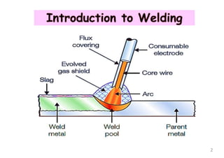
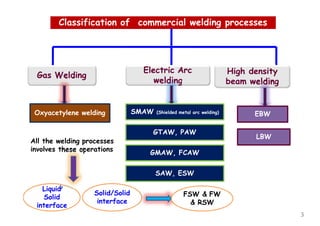
1. It classifies common welding processes and discusses factors like heat input, efficiency, and microstructural changes during welding.
2. It provides guidelines for designers like using fewer welded parts, ensuring proper joint fit-up and access, and specifying minimum weld sizes.
3. It discusses how to minimize distortion, residual stresses, and defects through techniques like multi-pass welding and preheating.
The document discusses welding symbols according to BS 499 part 2 and BS EN 22553 (ISO 2553) standards. It provides information on the components and rules for welding symbols, including arrow lines, reference lines, dimensions, and supplementary information. Examples of various weld types and symbols like fillet welds, butt welds, and flared flange welds are presented. Numerical codes for different welding processes are also listed. The document aims to explain the standards for welding symbols used on engineering drawings.
The document discusses residual stresses and distortion that occur during welding. It explains that residual stresses develop due to local expansion and contraction during welding, and are locked in as elastic strain. Distortion results from the movement caused by these welding stresses. The document outlines various factors that influence residual stress and distortion, such as heat input, restraint, and weld metal volume. It also discusses different types of distortion and several techniques for controlling distortion, such as joint design, offsetting, balanced welding, and clamping.
The document discusses various welding processes and their equipment requirements. It covers common electric arc welding processes like manual metallic arc welding (MMA), metal inert gas welding (MIG), and tungsten inert gas welding (TIG). It describes the power sources, current types, and constant current versus constant voltage characteristics used with different welding processes. It also discusses coated electrodes, the heat affected zone, and identification marking on electrodes.
This document discusses various types of weld discontinuities and defects including misalignment, undercut, insufficient fill, excessive reinforcement, overlap, burn-through, incomplete penetration, incomplete fusion, arc strikes, and inclusions such as slag, wagontracks, and tungsten. Each discontinuity or defect is defined, potential causes are identified, methods for prevention are provided, and repair techniques are described. The document serves as a reference for identifying and addressing common weld problems and defects.
This document discusses artifacts that may appear on radiographic films. It defines several types of artifacts including burned film, chemical stains, crimp marks, lead foil scratches, light leaks, pressure marks, sand/dirt marks, scratch marks, static marks, water marks, and roller marks from automatic processing. For each artifact, it provides an example radiographic image and brief description of how the artifact is caused. The purpose is to help trainees identify and understand artifacts that could affect the interpretation of radiographic images.
This document discusses distortion that can occur during welding processes. It defines distortion as any unwanted physical change to a fabricated structure due to welding. The main causes of distortion are non-uniform expansion/contraction from the welding thermal cycle and internal stresses formed in the base metal. The extent of distortion depends on material properties like thermal expansion and welding factors like process, amount of weld metal, and edge preparation. Different types of distortions like longitudinal, transverse, angular, bending, twisting and buckling are described. Methods to measure and control distortion include welding sequence, fixtures, preheating, and post weld heat treatment. Various materials have a welding suitability index calculated to indicate their distortion sensitivity during welding.
This document discusses various types of welding discontinuities and defects that can occur during the welding process. It divides discontinuities into six main groups: cracks, cavities, solid inclusions, lack of fusion and penetration, imperfect shape, and miscellaneous defects. Within each group it provides examples and descriptions of specific defect types like porosity, slag inclusions, undercut, burn through, and more. It also discusses potential causes of defects and recommended remedies.
Design for Manufacturability Guidelines Every Designer should FollowDFMPro
The document discusses design for manufacturability guidelines for sheet metal parts. It outlines several key DFM parameters like minimum bend radius, hole placement, cutout distances, notches and reliefs. Ignoring these guidelines can cause issues like cracks, deformation and breakage. Traditional DFM methods are manual and problematic. Automating DFM checks in a software tool called DFMPro allows early validation of designs and avoidance of costly rework. A case study of a hi-tech manufacturer found annual part cost savings of over 2 million euros through use of DFMPro's automated DFM analysis and guidelines.
Blackodising is a process that forms a corrosion-resistant coating on ferrous metals through a chemical reaction when immersed in a hot alkaline salt solution. This reaction converts the metal surface into magnetite (Fe3O4), providing protection without changing the part's dimensions. The black oxide coating has various applications and advantages, including corrosion resistance, an aesthetic black finish, and low cost processing, making it suitable for tool parts, fixtures, gears, and other mechanical components.
How to write a Welding Procedure Specification (ISO 15614-1Tiago Pereira
Some key aspects of writing welding procedure specifications. A good learning point for people who have no experience in the field, and a good reference for seasoned engineers
The document provides descriptions of common welding defects along with their corresponding radiographic images. It describes 14 different types of defects including misalignments, lack of penetration, inclusions, cracks, and more. Each defect entry explains what it is, such as offset or mismatch being a misalignment of pieces to be welded, and describes its radiographic image appearance, such as an abrupt change in film density across the weld image width. In total, it covers 14 common welding defects and their radiographic signatures for non-destructive testing interpretation.
This document discusses common casting defects such as surface defects, internal defects, incorrect chemical composition, and unsatisfactory mechanical properties. It defines casting defects and explains how they reduce output and increase production costs. Specific defects covered include swell, fins, gas holes, shrinkage cavities, hot tears, and cold shuts. For each defect, the causes and remedies are described. Even in modern foundries, the rejection rate can be as high as 20% of total castings produced due to these defects.
Welding causes distortion due to differential heating and cooling rates during the process. When heat is applied to part of a structure, it expands locally. If the structure is restrained from expanding uniformly, compressive and tensile stresses develop which can result in distortion. Three factors influence distortion: 1) temperature gradients between regions of the structure, 2) restraint from thermal expansion, and 3) yield strength and modulus of the material at welding temperatures. Distortion can be controlled by techniques such as pre-setting parts, clamping during welding, and post-weld heat treatment.
This document provides information on various earthing kits and components for electrical joints and terminations. It describes 3M armour continuity kits that provide electrical continuity across cable joints, along with accepted cable diameters and copper cord lengths. It also lists constant force springs, earth bonding kits, electrical shielding and grounding braids, and copper braid options for providing earth continuity and fault current paths. Technical support contact information is provided at the end.
The document discusses various welding defects including lamellar tearing, porosity, underfill, insufficient
penetration, wagon tracks, arc strikes, and incomplete fusion. Lamellar tearing occurs beneath welds in rolled steel
plate and is caused by transverse strain from welding, a weld orientation parallel to inclusions, and poor material
ductility. Porosity is caused by absorbed gases like nitrogen, oxygen, and hydrogen which become trapped during
solidification. Prevention methods for defects include using proper joint design, welding techniques, materials, and
preheating when necessary. Defects require removal and rewelding to repair.
Murex Hot-Cracking Test & Root-Pass Cracking Test Melwin Dmello
This Presentation covers the basic concepts of Murex Hot-Cracking Test & Root-Pass Cracking Test. For more information, please refer the books mentioned in the references slide.... Thank you
O documento discute os principais processos de conformação mecânica de metais, incluindo forjamento, laminação, trefilagem, extrusão e estampagem. Explica cada processo e como eles transformam a forma dos metais aplicando força externa para deformação plástica enquanto mantêm o volume e massa originais. O documento também discute trabalhos a quente e a frio durante a conformação mecânica.
1. Welding defects are discontinuities or irregularities in the weld that exceed code limits. Common defects include cracks, porosity, lack of fusion, undercut, and inclusions.
2. Defects can be caused by incorrect welding parameters, procedures, conditions, material selection, welder skill, or preparations.
3. Defects are classified as external/visual or internal/hidden. External defects are on the surface while internal defects exist below the surface.
The document discusses the effects of various welding parameters and techniques on weld quality. It identifies issues such as porosity, undercutting, improper reinforcement, burn-through, and cracking that can occur when parameters like current, voltage, speed, beveling, fit-up, wire position, and granular material depth are not properly set or techniques not properly followed. Maintaining correct welding parameters and techniques is important to produce welds without defects.
The document describes various visual indications that may appear on radiographic images of welds, including irregular densities, darker spots, lines, and changes in density. It also provides information on different radiographic testing methods, such as single wall single image, double wall single image, and double wall double image techniques. Acceptance criteria and standards for radiography from ASME and API are also mentioned.
Spraymet thermal spray and cladding ppt pump and valve sectorAnand, P T Bindagi
Spraymet Surface Technologies provides various surface modification processes at its plants in Bangalore and Pune, India, including thermal spray coatings, cladding, plating, and nitriding. Thermal spray processes include flame spray, robotic plasma spray, robotic high-velocity oxy-fuel spray (HVOF), and cold spray. Cladding techniques include plasma transferred arc spraying and high-energy tungsten inert gas welding. The company's services can be used to coat components for oil/gas, valves, pumps, and other industrial applications.
The document discusses various non-destructive testing (NDT) methods used to assess welds including penetrant testing, magnetic particle testing, ultrasonic testing, and radiographic testing. It provides details on the procedures, advantages, and disadvantages of each method. The document also covers topics like weld repairs, residual stresses and distortion from welding, and different heat treatments including annealing and normalizing.
This document discusses various types of welding defects and imperfections including lack of fusion, porosity, slag inclusions, and solidification cracking. It describes how to identify each type, their causes, best practices for prevention, acceptance standards, and methods for detection and remediation. The key types of imperfections are classified as fabrication defects occurring during welding or service defects that form during use, and guidelines are provided for minimizing defects and producing quality welds.
The document discusses design considerations for castings. It covers topics such as selecting a suitable casting process and material, designing the part for easy casting, locating gates and risers, avoiding defects, and economics. Key points include designing parts with uniform thickness and gradual changes to prevent shrinkage cavities, adding draft angles for removal from molds, and accounting for shrinkage and machining operations in patterns. Common defects like misruns, cold shuts and shrinkage cavities are also outlined. Economics depends on factors like materials, tooling, production rates and costs of melting, heat treating and inspection.
B.Sc. (Engineering)
Department of Mechanical Engineering
Khulna University of Engineering & Technology
Course - Manufacturing Process
Topic - Welding, Brazing & Soldering
The document discusses various welded joint geometries including butt, corner, T, lap, and edge joints as well as their advantages and disadvantages. It provides examples of different edge shapes and symbols used for each type of joint. Key terms are defined, such as butting member, nonbutting member, and splice member, and load reactions in welded joints are illustrated.
This document provides definitions for various defects that may appear on radiographic images of welds, including:
- Excessive root penetration appears as a light irregular band within the weld image.
- Root concavity appears as dark areas along the weld center varying in density by imperfection depth.
- Incomplete filled groove appears as a dark area at the weld center with diffuse edges.
- Cracks appear as dark, fine lines that are usually diffuse or discontinuous.
This document provides a reference guide for radiographers to interpret welds. It contains descriptions and examples of various types of discontinuities that can be detected in radiographic images of welds, including mismatches, lack of penetration, inclusions, cracks, porosity, and other defects. The guide defines each discontinuity type and provides details on their visual appearance on radiographs to aid in identification.
The document provides information on various welding processes and factors related to welding design and quality. It discusses different welding techniques, their typical applications based on production quantities, joint design considerations for minimizing distortion and stresses, non-destructive and destructive testing methods, and common welding defects such as lack of fusion, undercut, porosity, overlap and their causes.
The document discusses various types of welded joints, including lap joints, butt joints, and fillet welds. It describes the advantages of welded joints over riveted joints. Various welding processes are covered, including fusion welding processes like gas welding and electric arc welding. The document provides formulas to calculate the strength of different welded joint configurations, like transverse and parallel fillet welds, and discusses special cases like circular fillet welds subjected to torsion or bending moments. Design considerations for different welded joints are also presented.
The document discusses different types of mechanical joints used to connect parts in machinery. It describes three main types: bolted joints, which use bolts and nuts; screw joints, which use screws; and welded joints, which permanently fuse parts together. Welded joints include butt, corner, lap, tee, and edge joints. The document also discusses different welding processes like shielded metal arc welding, gas tungsten arc welding, gas metal arc welding, and submerged arc welding. It provides details on how each process works and its advantages and applications.
Welding is a process that joins materials by causing fusion and filling the joint with a filler material. There are several advantages to welding including lighter structures, maximum strength in joints, easy alterations, pleasing appearance, and strength equal to the parent material. Spot welding uses two electrodes to locally fuse materials and is commonly used in automotive and aircraft industries to join sheet metal. MIG welding uses an inert gas shield to prevent contamination and is often used for carbon/alloy steels, stainless steel, aluminum and other metals due to its high welding speed and economy. Common welding defects include lack of penetration, undercut, slag inclusion, porosity, cracks, spatter, and distortion.
The document discusses various welding techniques including thermit welding, submerged arc welding, electro-slag welding, and electro-gas welding. Thermit welding uses a thermite reaction to melt steel and fuse parts together. Submerged arc welding uses an arc beneath a blanket of flux to produce smooth, high strength welds at high speeds. Electro-slag and electro-gas welding use electric current passed through molten slag or an inert gas to fuse thick metals in a single pass without edge preparation.
Structural Damage and Maintenance Day 2tti-sharmila
The aim of this presentation is to provide a consistent test/fail guideline for light and heavy vehicle inspections that are in line with the RTA Guide.
The document discusses the design of welded joints. It begins by defining a welded joint as a permanent fusion of two parts achieved through heating and optionally applying pressure and a filler material. Welding provides advantages over riveted joints like lighter weight and greater efficiency. Various welding processes are described including gas, electric arc, thermit and forge welding. Common welded joint types like lap, butt, corner and T-joints are also outlined. The document then examines the strength calculations for transverse and parallel fillet welds as well as butt joints. It concludes by discussing stresses in eccentrically loaded and unsymmetrical welded sections.
Welding can be a useful skill for homeowners and DIYers. There are several types of welders available for different applications, including arc, MIG, TIG, and oxygen/acetylene. MIG and flux-core arc welders have become popular choices for homeowners as they produce clean welds and are relatively easy to learn. However, welding safety must always be followed by wearing protective gear like gloves and helmets. With practice, welding can be a fun and rewarding skill.
The document analyzes rivets using finite element analysis. It discusses rivet design, materials, and joining techniques like cold riveting and hot riveting. Finite element analysis software ANSYS is used to model and analyze single lap riveted joints with and without adhesive. Results show stresses and deformations in the rivet and joint. The analysis finds finite element methods to be effective for designing mechanical components like riveted joints, and ANSYS can accurately model complex joint geometries. Using adhesives between plates leads to more uniform stress distribution and increased joint life.
Welded connections in steel structures - Limit State Design of Steel StructuresAshishVivekSukh
Two members are connected by means of welds is known as welded connection.
More efficient use of the materials.
Earlier designers considered welds as less fatigue resistant.
Good welds achive at site is impossible.
Testing and quality control of welds became easier because NDT
The document provides information on various welding processes including arc welding, gas welding, resistance welding, and MIG welding. It discusses the basic principles, types, equipment, and applications of each process. For arc welding, it explains how the electric arc is used to join metals and lists the common types such as carbon arc, metal arc, TIG, and plasma arc welding. It also outlines the advantages and disadvantages of each process.
Welds can fail due to several causes: overload, poor joint design, or bad welding methods. Proper joint design is important to ensure good fusion and avoid defects from rapid heat dissipation. Welding procedures must be qualified to produce acceptable quality welds, and welders must pass approval tests to demonstrate their skills match the approved procedures. Supervision by qualified personnel is also important when carrying out welding operations.
The document provides information on welding inspection, including the roles and duties of welding inspectors. It discusses inspecting welds prior to, during, and after welding. It also summarizes common weld defects that inspectors examine for, such as cracks, porosity, lack of fusion, and improper weld size or shape. Inspection tools like weld profile gauges and hi-lo gauges are described. Non-destructive testing methods for inspecting welds are also briefly mentioned.
The Certified Welding Inspector (CWI) plays an important role during any welded construction activities ensuring the required specifications and standards are followed. Due to the numerous materials and processes associated with metal joining (welding) THIS PRESENTATION SHALL SHOW ONLY THE BASIC WELDING PROCESSES AND EXAMINATION METHODS (NDE). National and International Codes and Specifications along with measuring devices are the Inspector’s tools. Hopefully the following presentation shall give an insight into basic welding inspection.
IRJET- Design and Development of Joining Method to Overcome Failure of Braze ...IRJET Journal
The document discusses improvements made to the joining method used in cassette containers. Originally, braze welding was used but failed during inspections due to low strength. To address this, spot welding was implemented as it has higher strength than braze welding. Spot welding involves applying pressure and electrical current to join overlapping metal pieces. This creates strong fused nugget joints. Testing found the spot welded joints could withstand forces 38% higher than the braze welded joints before failure. The improved joining method allows the cassette containers to pass inspections while increasing productivity and reducing production time.
The document discusses various metal joining processes, focusing on welding. It describes different types of welding processes, including arc welding, gas welding, resistance welding, and solid state welding. For arc welding processes specifically, it explains gas metal arc welding (MIG), shielded metal arc welding (SMAW), submerged arc welding (SAW), and the consumable electrodes, shielding gases, and power sources used.
This document reviews optimization of the submerged arc welding (SAW) process. SAW is commonly used in industry due to its high deposition rate and ability to be automated. The quality of a welded joint depends on weld bead geometry and mechanical properties, which are determined by welding input parameters like current, voltage, wire feed speed, and wire diameter. The document summarizes SAW principles, methods like single-wire and twin-arc welding, and important process parameters. It also reviews literature on using methods like Taguchi analysis and response surface methodology to optimize SAW parameters and bead quality. In conclusion, it identifies gaps in literature regarding metal transfer behavior, current-voltage transient studies, and the effect of polarity changes on
What is MIG welding?
Working process
Process Parameters
Advantages
Limitations
Applications
MIG welding is an arc welding process in which a continuous solid wire electrode is fed through a welding gun and into the weld pool, joining the two base materials together.
A shielding gas is also sent through the welding gun and protects the weld pool from contamination.
In fact, MIG stands for “Metal Inert Gas”. The technical name for it is "Gas Metal Arc Welding" (or GMAW).
Understanding - different welding process, how to specify welding details in drawing, selection of different welding process, selection of shielding gas
Introduction to python & its applications.pptPradeepNB2
Python is an interpreted, object-oriented programming language created in the 1990s. It has an interactive environment for testing code. Python code is written in plain text files and executed line by line. It supports common programming constructs like functions, conditionals, loops, lists, dictionaries, and more. The syntax is designed to be simpler than languages like C/C++. Python code is portable across many operating systems.
This document provides information about a course on CNC Machine Tools. It outlines 5 modules that will be covered in the course: 1) Introduction to CNC Machine Tools, 2) Structure of CNC Machine Tools, 3) Drives and Controls, 4) CNC Programming, and 5) Tooling and Work Holding Devices. Each module will cover topics related to the components, programming, and applications of CNC machine tools.
The document discusses design considerations to facilitate machining operations like milling, drilling, and keyway generation. Some of the key points discussed are:
1) Parts should be designed to be easily fixtured and held securely for machining. Interrupted cuts and machining of hardened materials should be avoided.
2) Features like holes, slots, and surfaces should be located and oriented to allow them to be machined efficiently using standard cutting tools in sequential operations without repositioning the part.
3) Part dimensions and tolerances should allow for machining stock removal and avoid unnecessary small tolerance finishes.
The document provides design considerations and guidelines for parts manufactured through powder metallurgy. Some key points include:
- Part shapes should be simple to allow for easy ejection from the die without damaging the compact.
- Wall thicknesses should generally be at least 1.5mm thick to prevent issues during pressing.
- Dimensional tolerances are typically ±0.05 to 0.1mm, but additional operations can improve tolerances.
- Designs should allow for strong die construction and minimize changes in thickness. Basic shapes like rounds, squares and straight holes are preferable to complex geometries.
Welding, soldering, and brazing are methods of joining metal pieces. Welding joins metals using only heat or heat and pressure. It is classified into pressure welding and non-pressure welding. Soldering joins similar or dissimilar metals using a filler metal with a melting point below 450°C. It is classified into soft and hard soldering. Brazing also joins similar or dissimilar metals, but uses a special fusible alloy and flux above the alloy's melting point to form a bond.
Automation is a technology that uses mechanical, electronic, and computer systems to operate and control production. This includes automatic machine tools, assembly machines, industrial robots, material handling systems, inspection systems, and computer systems for planning and decision making. Automation strategies aim to specialize, combine, or integrate operations to make them more efficient and flexible while reducing non-productive time through improved material handling and storage. The principles of automation involve understanding, simplifying, and automating processes. Advanced functions provide safety monitoring, maintenance diagnostics, and error detection and recovery to enhance performance and safety.
Batteries -Introduction – Types of Batteries – discharging and charging of battery - characteristics of battery –battery rating- various tests on battery- – Primary battery: silver button cell- Secondary battery :Ni-Cd battery-modern battery: lithium ion battery-maintenance of batteries-choices of batteries for electric vehicle applications.
Fuel Cells: Introduction- importance and classification of fuel cells - description, principle, components, applications of fuel cells: H2-O2 fuel cell, alkaline fuel cell, molten carbonate fuel cell and direct methanol fuel cells.
A SYSTEMATIC RISK ASSESSMENT APPROACH FOR SECURING THE SMART IRRIGATION SYSTEMSIJNSA Journal
The smart irrigation system represents an innovative approach to optimize water usage in agricultural and landscaping practices. The integration of cutting-edge technologies, including sensors, actuators, and data analysis, empowers this system to provide accurate monitoring and control of irrigation processes by leveraging real-time environmental conditions. The main objective of a smart irrigation system is to optimize water efficiency, minimize expenses, and foster the adoption of sustainable water management methods. This paper conducts a systematic risk assessment by exploring the key components/assets and their functionalities in the smart irrigation system. The crucial role of sensors in gathering data on soil moisture, weather patterns, and plant well-being is emphasized in this system. These sensors enable intelligent decision-making in irrigation scheduling and water distribution, leading to enhanced water efficiency and sustainable water management practices. Actuators enable automated control of irrigation devices, ensuring precise and targeted water delivery to plants. Additionally, the paper addresses the potential threat and vulnerabilities associated with smart irrigation systems. It discusses limitations of the system, such as power constraints and computational capabilities, and calculates the potential security risks. The paper suggests possible risk treatment methods for effective secure system operation. In conclusion, the paper emphasizes the significant benefits of implementing smart irrigation systems, including improved water conservation, increased crop yield, and reduced environmental impact. Additionally, based on the security analysis conducted, the paper recommends the implementation of countermeasures and security approaches to address vulnerabilities and ensure the integrity and reliability of the system. By incorporating these measures, smart irrigation technology can revolutionize water management practices in agriculture, promoting sustainability, resource efficiency, and safeguarding against potential security threats.
Embedded machine learning-based road conditions and driving behavior monitoringIJECEIAES
Car accident rates have increased in recent years, resulting in losses in human lives, properties, and other financial costs. An embedded machine learning-based system is developed to address this critical issue. The system can monitor road conditions, detect driving patterns, and identify aggressive driving behaviors. The system is based on neural networks trained on a comprehensive dataset of driving events, driving styles, and road conditions. The system effectively detects potential risks and helps mitigate the frequency and impact of accidents. The primary goal is to ensure the safety of drivers and vehicles. Collecting data involved gathering information on three key road events: normal street and normal drive, speed bumps, circular yellow speed bumps, and three aggressive driving actions: sudden start, sudden stop, and sudden entry. The gathered data is processed and analyzed using a machine learning system designed for limited power and memory devices. The developed system resulted in 91.9% accuracy, 93.6% precision, and 92% recall. The achieved inference time on an Arduino Nano 33 BLE Sense with a 32-bit CPU running at 64 MHz is 34 ms and requires 2.6 kB peak RAM and 139.9 kB program flash memory, making it suitable for resource-constrained embedded systems.
Advanced control scheme of doubly fed induction generator for wind turbine us...IJECEIAES
This paper describes a speed control device for generating electrical energy on an electricity network based on the doubly fed induction generator (DFIG) used for wind power conversion systems. At first, a double-fed induction generator model was constructed. A control law is formulated to govern the flow of energy between the stator of a DFIG and the energy network using three types of controllers: proportional integral (PI), sliding mode controller (SMC) and second order sliding mode controller (SOSMC). Their different results in terms of power reference tracking, reaction to unexpected speed fluctuations, sensitivity to perturbations, and resilience against machine parameter alterations are compared. MATLAB/Simulink was used to conduct the simulations for the preceding study. Multiple simulations have shown very satisfying results, and the investigations demonstrate the efficacy and power-enhancing capabilities of the suggested control system.
International Conference on NLP, Artificial Intelligence, Machine Learning an...gerogepatton
International Conference on NLP, Artificial Intelligence, Machine Learning and Applications (NLAIM 2024) offers a premier global platform for exchanging insights and findings in the theory, methodology, and applications of NLP, Artificial Intelligence, Machine Learning, and their applications. The conference seeks substantial contributions across all key domains of NLP, Artificial Intelligence, Machine Learning, and their practical applications, aiming to foster both theoretical advancements and real-world implementations. With a focus on facilitating collaboration between researchers and practitioners from academia and industry, the conference serves as a nexus for sharing the latest developments in the field.
Comparative analysis between traditional aquaponics and reconstructed aquapon...bijceesjournal
The aquaponic system of planting is a method that does not require soil usage. It is a method that only needs water, fish, lava rocks (a substitute for soil), and plants. Aquaponic systems are sustainable and environmentally friendly. Its use not only helps to plant in small spaces but also helps reduce artificial chemical use and minimizes excess water use, as aquaponics consumes 90% less water than soil-based gardening. The study applied a descriptive and experimental design to assess and compare conventional and reconstructed aquaponic methods for reproducing tomatoes. The researchers created an observation checklist to determine the significant factors of the study. The study aims to determine the significant difference between traditional aquaponics and reconstructed aquaponics systems propagating tomatoes in terms of height, weight, girth, and number of fruits. The reconstructed aquaponics system’s higher growth yield results in a much more nourished crop than the traditional aquaponics system. It is superior in its number of fruits, height, weight, and girth measurement. Moreover, the reconstructed aquaponics system is proven to eliminate all the hindrances present in the traditional aquaponics system, which are overcrowding of fish, algae growth, pest problems, contaminated water, and dead fish.
Introduction- e - waste – definition - sources of e-waste– hazardous substances in e-waste - effects of e-waste on environment and human health- need for e-waste management– e-waste handling rules - waste minimization techniques for managing e-waste – recycling of e-waste - disposal treatment methods of e- waste – mechanism of extraction of precious metal from leaching solution-global Scenario of E-waste – E-waste in India- case studies.
Using recycled concrete aggregates (RCA) for pavements is crucial to achieving sustainability. Implementing RCA for new pavement can minimize carbon footprint, conserve natural resources, reduce harmful emissions, and lower life cycle costs. Compared to natural aggregate (NA), RCA pavement has fewer comprehensive studies and sustainability assessments.
Redefining brain tumor segmentation: a cutting-edge convolutional neural netw...IJECEIAES
Medical image analysis has witnessed significant advancements with deep learning techniques. In the domain of brain tumor segmentation, the ability to
precisely delineate tumor boundaries from magnetic resonance imaging (MRI)
scans holds profound implications for diagnosis. This study presents an ensemble convolutional neural network (CNN) with transfer learning, integrating
the state-of-the-art Deeplabv3+ architecture with the ResNet18 backbone. The
model is rigorously trained and evaluated, exhibiting remarkable performance
metrics, including an impressive global accuracy of 99.286%, a high-class accuracy of 82.191%, a mean intersection over union (IoU) of 79.900%, a weighted
IoU of 98.620%, and a Boundary F1 (BF) score of 83.303%. Notably, a detailed comparative analysis with existing methods showcases the superiority of
our proposed model. These findings underscore the model’s competence in precise brain tumor localization, underscoring its potential to revolutionize medical
image analysis and enhance healthcare outcomes. This research paves the way
for future exploration and optimization of advanced CNN models in medical
imaging, emphasizing addressing false positives and resource efficiency.
Electric vehicle and photovoltaic advanced roles in enhancing the financial p...IJECEIAES
Climate change's impact on the planet forced the United Nations and governments to promote green energies and electric transportation. The deployments of photovoltaic (PV) and electric vehicle (EV) systems gained stronger momentum due to their numerous advantages over fossil fuel types. The advantages go beyond sustainability to reach financial support and stability. The work in this paper introduces the hybrid system between PV and EV to support industrial and commercial plants. This paper covers the theoretical framework of the proposed hybrid system including the required equation to complete the cost analysis when PV and EV are present. In addition, the proposed design diagram which sets the priorities and requirements of the system is presented. The proposed approach allows setup to advance their power stability, especially during power outages. The presented information supports researchers and plant owners to complete the necessary analysis while promoting the deployment of clean energy. The result of a case study that represents a dairy milk farmer supports the theoretical works and highlights its advanced benefits to existing plants. The short return on investment of the proposed approach supports the paper's novelty approach for the sustainable electrical system. In addition, the proposed system allows for an isolated power setup without the need for a transmission line which enhances the safety of the electrical network
A review on techniques and modelling methodologies used for checking electrom...nooriasukmaningtyas
The proper function of the integrated circuit (IC) in an inhibiting electromagnetic environment has always been a serious concern throughout the decades of revolution in the world of electronics, from disjunct devices to today’s integrated circuit technology, where billions of transistors are combined on a single chip. The automotive industry and smart vehicles in particular, are confronting design issues such as being prone to electromagnetic interference (EMI). Electronic control devices calculate incorrect outputs because of EMI and sensors give misleading values which can prove fatal in case of automotives. In this paper, the authors have non exhaustively tried to review research work concerned with the investigation of EMI in ICs and prediction of this EMI using various modelling methodologies and measurement setups.
Harnessing WebAssembly for Real-time Stateless Streaming PipelinesChristina Lin
Traditionally, dealing with real-time data pipelines has involved significant overhead, even for straightforward tasks like data transformation or masking. However, in this talk, we’ll venture into the dynamic realm of WebAssembly (WASM) and discover how it can revolutionize the creation of stateless streaming pipelines within a Kafka (Redpanda) broker. These pipelines are adept at managing low-latency, high-data-volume scenarios.
Harnessing WebAssembly for Real-time Stateless Streaming Pipelines
DFM welding.pptx
1. Reference:
James G. Bralla, Design for manufacturability Hand
book, McGraw Hill Publications
By
Pradeep N B
Assistant Professor
Department of Mechanical Engineering
JNNCE, Shivamogga
1
3. Classification of commercial welding processes
Gas Welding
Electric Arc
welding eldin
High density
beam w g
Oxyacetylene welding SMAW (Shielded metal arc welding)
GTAW, PAW
GMAW, FCAW
SAW, ESW
EBW
LBW
All the welding processes
involves t erations
hese op
/
Liquid
Solid
interface
Solid/Solid
interface
FSW & FW
& RSW
3
5. Interaction of different metals (similar & dissimilar)
Interaction of metals with atmospheric gases within a short
period of time
Solubility of
atmospheric gases
and the effect of
shielding gases
with molten
weldment
Solid state
transformation
during cooling
after welding
Microstructural
changes in
weldment and
HAZ after
welding
Influence of
welding
parameters on
welding process
Effect of
impurities in
the weld
Changes in
Mechanical &
Corrosion
properties
5
6. What will happen, when the weld metal
is in hot liquid state ?
Molten weld pool semi solid weld fully solidified weldment
1. No distinct structure
in the
atoms
2. No orderliness
arrangement of
3. High degree of mobility
between atoms due
heat energy involved
to
in
welding.
When molten weld cools, atoms loose their energy and their
mobility and formed into a definite patterns.
These patterns are arranged in a three dimensional form and
forms a crystalline solid.
6
7. Efficiency of welding:
Where ,
the work piece
Q = Heat transfer rate from the heat source to
Qnominal = Nominal power of the heat source
Always efficiency is less than 100% due to the lose of heat to the
surroundings during welding.
Where, E = Arc voltage; I = welding current and V = Welding speed
Q = EI/V
Heat input per unit length of the weld
7
11. Welded assemblies should be made up of as few parts as
possible.
Metal forming and machining operations are almost always
less costly than welding.
Cost reduction
11
12. Designers should develop at least part of the configuration of
their assemblies by forming and machining instead of welding.
Weld joints should be placed so that there is room for easy
access of the welding nozzle. (Particularly for welding methods
that use a wire feed and a shielding gas).
It is important that the nozzle be close to the welding point
so that the molten metal is well shielded.
12
13. Designers should specify the minimum amount of weld filler, with respect to
both fillet size and length, that meets functional requirements of the assembly
.
13
14. Tack welds should be specified if the application does not involve high
stresses or a leak proof construction.
14
15. Designers have the responsibility for making whatever calculations, analyses,
or tests necessary to specify the sizes and types of welded joints rather
than simply to specify “Weld parts together.”
Whenever possible assembly should be designed so that the welded joint is
horizontal, with the stick or electrode holder pointing downward during
welding.
This position is the most rapid and convenient with all welding methods.
It is preferable to locate welds out of sight rather than in locations where
special finishing operations are required for the sake of appearance.
15
16. Good fit-up of parts at the weld joint is essential not only for welding speed but
also for minimizing distortion of the finished weldment.
Especially with butt joints, edges of work pieces should be straight and uniform.
Often, the extra operation required to provide a straight edge will be less costly
than the extra welding labor required when the fit is not correct.
Poor and good fit-up of weld joints
16
18. Poor and good fit-up of weld joints
The build-up of weld fillets should be kept to a minimum. Additional material
in the convex portion of the fillet’s cross section does not add significantly to
the strength of the joint.
18
19. When forgings or castings are part of a welded assembly, care should be taken
to ensure good fit-up of the parts to be welded.
Untrimmed parting-line areas should not be included in the welded joint.
The casting should also be designed so that the wall thickness of both parts to
be joined is equal at the joint. This ensures more rapid and less distortion-
prone welding.
19
20. The joint should be designed so that it requires minimal edge preparation.
lap joints are advisable to avoid the cost of close edge preparation and to
simplify fit-up problems.
But lap joints are more difficult to clean, finish, and repair and frequently
have root defects.
20
21. Joints that have natural grooves and thus need little or no edge
preparation.
Equivalent of a grooved edge for the welded joint.
Total operation time is reduced.
21
22. If machining after welding is required, welds should be placed away from
the material to be machined.
This will avoid machining problems which can occur in the heat-affected
zone.
22
23. It is often advisable to utilize a number of welded subassemblies in the
fabrication of a large, complex final assembly.
Subassemblies can be handled more easily.
They can be positioned for easy access of the electrode, and the joint can be
kept horizontal during welding.
When machining a groove on the end of a cylindrical component to be welded by
submerged arc, it sometimes is advantageous to include a backup strip as an
integral part of the component to be welded.
23
24. Causes for distortion
• Localized heating
•Non uniform stress distribution
Distortion occurs in these forms:
Longitudinal shrinkage
Transverse shrinkage
Angular distortion
Distortion
24
25. Types of Distortion
Shrinkage
Angular distortion
Buckling deformation
Rotational deformation
All the distortions are caused by the
shrinkage force generated due to the
thermal loading on the structure.
A single V groove butt weld leads to more distortion than the double V
groove butt weld of same thickness plate.
25
26. Welding in neutral axis will balance the shrinkage force
against another side from the neutral axis.
of one side
26
27. Dimensional Inaccuracy caused by Distortion
Weld
direction
Dimensional accuracy is very important in
welding. Heat flow in the direction
perpendicular to the weld line is more.
Transverse shrinkage
Transverse shrinkage > longitudinal
shrinkage
longitudinal shrinkage
27
29. Minimizing Distortion
Good fit of parts (maximum contact of all mating surfaces is desirable) is
important not only for minimum welding time but also for control of distortion.
The more gap to fill, the greater the possible weldment distortion.
When dimensioning welded assemblies, it is essential that consideration be given
to the shrinkage inherent in each weld.
29
30. Heavier sections are less prone to distortion from welding.
Designers should consider the use of thicker, more rigid components.
A short-flanged butt joint is often preferable for joining long sections of
thinner material.
Minimizing Distortion
Suited for autogenous welding
Whenever possible, place welds opposite one another to reduce distortion
(shrinkage forces in the weld fillets are balanced).
To avoid angular distortion
30
31. If sections of unequal thickness must be welded together, distortion can be
reduced by machining a groove in the thicker piece adjacent to the weld
joint.
Minimizing Distortion
Avoid over welding – The bigger the weld, the greater the shrinkage.
Correctly sizing a weld not only minimizes distortion, but also saves weld
metal and time.
Fewer weld passes — A fewer number of big passes results in less distortion
than a greater number of small passes with small electrodes. Shrinkage
accumulates from each weld pass.
31
32. Design recommendations for weld strength
If deep-penetration welding is used or the stock thickness is not
great, the square-edged butt joint can be employed and edge-
preparation time therefore saved.
Thicker stock or less penetrating methods may require grooved
edges.
For efficient and economical welding, minimize the stress that the joint must
carry.
This can be achieved by locating weld joints away from areas of stress or
designing the assembly so that the parts themselves rather than the weld joints
bear the load.
32
33. Weldments should be designed so that welds are placed to minimize stress
concentration in the weld fillet.
33
34. Groove welds should be designed to be in either compression or tension.
Fillet welds should be in shear only.
Post weld heat treatment should be carried out if necessary.
34
35. Electron and Laser Beam Weldments
The narrow width and deep penetration inherent in these welding processes make
butt joints preferable to lap joints.
Beveled edges are not needed and, in fact, should be avoided.
However, good fit-up of the mating pieces is essential because of the narrow beam.
Ref: https://doi.org/10.1016/j.vacuum.2016.05.004
35
36. Economic Production Quantities
Oxyfuel Gas Welding Low equipment and tooling cost, slower heating rate, used for repair and low-
quantity work.
Stick Welding Low equipment and tooling cost, faster than gas welding, slower than with other arc-
welding processes (because of electrode changes and slag removal as well as welding time).
Submerged Arc Welding Equipment and tooling costs are high, metal deposition rate, is quite rapid,
used for large-quantity work, particularly when seams are long.
Flux-Cored Welding requires relatively expensive equipment, particularly if shielding gas also is used,
slag-removal labor is required, welding rates are high.
Gas-Metal Arc Welding suitable for higher production levels, low in labor cost, electrode is fed
continuously.
Gas-Tungsten Arc Welding Applicable to low-production work.
Plasma Arc Welding 2 to 5 times the cost of GTAW equipment, very rapid, producing welds at four or
more times the rate of other arc processes, capability to make deep-penetration welds.
36
37. Residual stresses
Residual stresses causes
• Stress corrosion cracking
• Hydrogen induced cracking
• Fatigue crack
Controlling residual stress
Proper edge preparation
Minimize heat input
Preheating
No of passes during welding
Distortion
Stress pattern in longitudinal &Transverse
directions
37
38. Destructive Tests – Tensile Test
The tension testing of welds is somewhat more involved than for base
metal because the weld test section is heterogeneous in nature, composed
of the deposit weld metal, the HAZ and the unaffected base metal.
Tensile test specimen can be either transverse or longitudinal depends on
the loading on the welded joint.
If the weld metal strength exceeds that of
the base metal, most of the plastic strain
occurs in the base metal and failure outside
of the area.
When the weld strength is considerably
lower than that of the base metal, most of
the plastic strain occurs in the weld.
38
39. Destructive Tests – Tension-shear Test
The tension-shear test is the most widely used method for determining
the strength of resistance spot welds.
Destructive Tests – Bend Test
To measure the ductility and crack sensitivity of the welds
39
40. Dye penetrant testing in welds
Pre-cleaning Application of penetrant Excess penetrant removal
Application of developer Inspection
This method is
used to detect
the surface
defects
40
41. Magnetic particle Inspection in welds
Used for detecting surface in
ferromagnetic materials such
their alloys.
and slightly subsurface
as iron, nickel, cobalt,
discontinuities
and some of
The presence of a surface or subsurface discontinuity in the material allows
the magnetic flux to leak.
Ferrous iron particles are applied to the part, the particles will be attracted
to this area.
41
42. Ultrasonic Examinations
This method that employs mechanical vibrations with a higher frequency
to detect the defects.
Ultrasonic beam travels through a material, except when it is intercepted
and reflected by a discontinuity or by a change in material.
When the pulse of ultrasonic waves strikes a discontinuity in the test
piece, it is reflected back to its point of origin.
42
43. Lack Of Fusion
Weld metal and the base metal are not fused together.
Possible Causes:
Travel Speed Too Fast
Insufficient root gap and low bevel angle
Excessive filler wire diameter
Possible Cures:
Increase Current and voltage
Use Proper Travel Speed
43
44. Undercut
Edges of the joint to melt and drain into the weld
Possible causes:
Excessive current
Improper rod angle (Too small electrode angle)
Arc length too long
Slow speed
Using an incorrect filler metal, because it will create greater
temperature gradients between the center of the weld and the
edges
Ways to minimize undercut:
Shorten arc length
Use correct arc length
Lower machine setting
44
45. Porosity
Porosity is tiny holes in the weld. It can resemble a sponge and it
weakens a weld.
Common causes :
Arc length too long
Base metal not cleaned/impurities
Electrode contamination/moisture
Solutions for porosity:
Clean base metal
Shorten arc length
Use good dry electrodes
45
46. Overlap
Overlap is where the edges of the weld bead is not fused to the
base metal. It appears as if the weld is just sitting on top of the
metal.
Common causes:
Travel speed too slow
Welding machine setting too
low
Possible solutions:
Use correct machine setting
Increase travel speed
46