SlideShare a Scribd company logo
Automated Assembly System
Dept of Mechanical Engineering MSRIT, Bangalore Page 1
Automated Assembly Systems
Introduction
Assembly involves the joining together of two or more separate parts
to form new entity which may be assembly or subassembly.
Automated assembly refers to the use of mechanized and automated
devices to perform the various functions in an assembly line or cell.
Automated assembly system performs a sequence of automated
operations to combine multiple components in to a single entity
which can be a final product or sub assembly.
Automated assembly technology should be considered when the
following condition exists.
 High product demand
 Stable product design
 The assembly consists of no more than a limited number of
components.
 The product is designed for automated assembly.
Automated assembly system involves less investment compared to
transfer lines because
1. Work part produced are smaller in size compared to transfer lines.
2. Assembly operations do not have the large mechanical forces and
power requirement
3. Size is very less compared to transfer lines.
Automated Assembly System
Dept of Mechanical Engineering MSRIT, Bangalore Page 2
DESIGNS FOR AUTOMATED ASSEMBLY
Recommendations and principles that can be applied in product
design to facilitate automated assembly
Reduce the amount of assembly required: This principle can be
realized during design by combining functions within the same part
that were previously accomplished by separate components in the
product. The use of plastic molded parts to substitute for sheet metal
parts is an example of this principle. A more complex geometry
molded into a plastic part might replace several metal parts. Although
the plastic part may seem to be more costly, the savings-in assembly
time probably justify the substitution in many cases.
Use modular design: In automated assembly, increasing the number
of separate assembly steps that are done by a single automated system
will result in an increase in the downtime of the system. To reduce
this effect, Riley suggests that the design of the product be modular,
with perhaps each module requiring a maximum of 12 or 13 parts to
be assembled on a single assembly system. Also, the subassembly
should be designed around a base part to which other components are
added.
Reduce the number of fasteners required: Instead of using
separate screws and nuts, and similar fasteners, design the fastening
mechanism into the component design using snap fits and similar
features. Also, design the product modules so that several
components are fastened simultaneously rather than each component
fastened separately.
Automated Assembly System
Dept of Mechanical Engineering MSRIT, Bangalore Page 3
Reduce the need for multiple components to lie handled at once:
The preferred practice in automated assembly machine design is to
separate the operations at different stations rather than to handle and
fasten multiple components simultaneously at the same workstation.
(It should be noted that robotics technology is causing a rethinking of
this practice since robots can be programmed to perform more
complex assembly tasks than a single station in a mechanized
assembly system.
Limit the required directions of access: This principle simply
means that the number of directions in which new components are
added to the existing subassembly should be minimized. If all of the
components can be added vertically from above, this is the ideal
situation. Obviously, the design of the subassembly module
determines this.
Require high quality in components: High performance of the
automated assembly system requires consistently good quality of the
components that are added at each workstation. Poor-quality
components cause jams in the feeding and assembly mechanisms
which cause downtime in the automated system.
Implement hopperability: This is a term that is used to identify the
ease with which a given component can be fed and oriented reliably
for delivery from the parts hopper to the assembly workhead.
Automated Assembly System
Dept of Mechanical Engineering MSRIT, Bangalore Page 4
TYPES OF AUTOMATED ASSEMBLY SYSTEMS
Based on the type of work transfer system that is used in the assembly
system:
• Continuous transfer system
• Synchronous transfer system
• Asynchronous transfer system
• Stationary base part system
The first three types involve the same methods of workpart transport
described in automated flow line. In the stationary base part system,
the base part to which the other components are added is placed in a
fixed location, where it remains during the assembly work.
Based on physical configuration:
• Dial-type assembly machine
• In-line assembly machine
• Carousel assembly system
• Single-station assembly machine
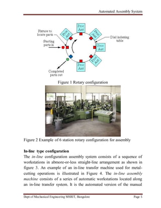
The dial-type machine, the base partare indexed around a circular
table or dial. The workstations are stationary and usually located
around the outside periphery of the dial. The parts ride on the rotating
table and arc registered or positioned, in turn, at each station a new
component is added to base part. This type of equipment is often
referred to as an indexing machine or dial index machine and the
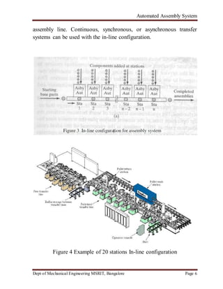
configuration is shown in Figure 1 and example of six station rotary
shown in figure 2.
Automated Assembly System
Dept of Mechanical Engineering MSRIT, Bangalore Page 5
Figure 1 Rotary configuration
Figure 2 Example of 6 station rotary configuration for assembly
In-line type configuration
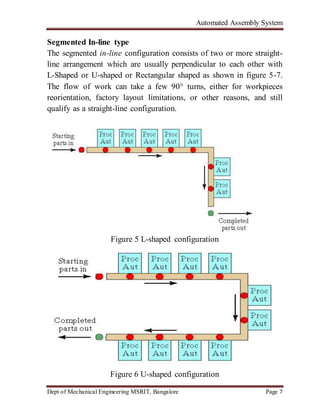
The in-line configuration assembly system consists of a sequence of
workstations in abmore-or-less straight-line arrangement as shown in
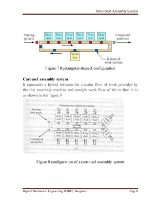
figure 3. An example of an in-line transfer machine used for metal-
cutting operations is illustrated in Figure 4. The in-line assembly
machine consists of a series of automatic workstations located along
an in-line transfer system. It is the automated version of the manual
Automated Assembly System
Dept of Mechanical Engineering MSRIT, Bangalore Page 6
assembly line. Continuous, synchronous, or asynchronous transfer
systems can be used with the in-line configuration.
Figure 4 Example of 20 stations In-line configuration
Automated Assembly System
Dept of Mechanical Engineering MSRIT, Bangalore Page 7
Segmented In-line type
The segmented in-line configuration consists of two or more straight-
line arrangement which are usually perpendicular to each other with
L-Shaped or U-shaped or Rectangular shaped as shown in figure 5-7.
The flow of work can take a few 90° turns, either for workpieces
reorientation, factory layout limitations, or other reasons, and still
qualify as a straight-line configuration.
Figure 5 L-shaped configuration
Figure 6 U-shaped configuration
Automated Assembly System
Dept of Mechanical Engineering MSRIT, Bangalore Page 8
Figure 7 Rectangular-shaped configuration
Carousel assembly system
It represents a hybrid between the circular flow of work provided by
the dial assembly machine and straight work flow of the in-line. It is
as shown in the figure 8
Figure 8 configuration of a carrousel assembly system
Automated Assembly System
Dept of Mechanical Engineering MSRIT, Bangalore Page 9
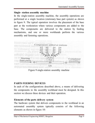
Single- station assembly machine
In the single-station assembly machine, the assembly operations are
performed at a single location (stationary base part system) as shown
in figure 9. The typical operation involves the placement of the base
part at the workstation where various components are added to the
base. The components are delivered to the station by feeding
mechanisms, and one or more workheads perform the various
assembly and fastening operations.
Figure 9 single-station assembly machine
PARTS FEEDING DEVICES
In each of the configurations described above, a means of delivering
the components to the assembly workhead must be designed. In this
section we discuss these devices and their operation.
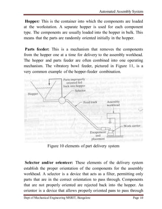
Elements of the parts delivery system
The hardware system that delivers components to the workhead in an
automated assembly system typically consists of the following
elements as shown in figure 10:
Automated Assembly System
Dept of Mechanical Engineering MSRIT, Bangalore Page 10
Hopper: This is the container into which the components are loaded
at the workstation. A separate hopper is used for each component
type. The components are usually loaded into the hopper in bulk. This
means that the parts are randomly oriented initially in the hopper.
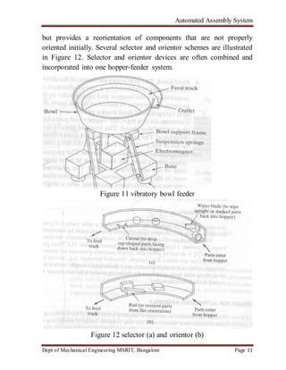
Parts feeder: This is a mechanism that removes the components
from the hopper one at a time for delivery to the assembly workhead.
The hopper and parts feeder are often combined into one operating
mechanism. The vibratory bowl feeder, pictured in Figure 11, is a
very common example of the hopper-feeder combination.
Figure 10 elements of part delivery system
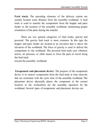
Selector and/or orienteer: These elements of the delivery system
establish the proper orientation of the components for the assembly
workhead. A selector is a device that acts as a filter, permitting only
parts that are in the correct orientation to pass through. Components
that are not properly oriented are rejected back into the hopper. An
orientor is a device that allows properly oriented pans to pass through
Automated Assembly System
Dept of Mechanical Engineering MSRIT, Bangalore Page 11
but provides a reorientation of components that are not properly
oriented initially. Several selector and orientor schemes are illustrated
in Figure 12. Selector and orientor devices are often combined and
incorporated into one hopper-feeder system.
Figure 11 vibratory bowl feeder
Figure 12 selector (a) and orientor (b)
Automated Assembly System
Dept of Mechanical Engineering MSRIT, Bangalore Page 12
Feed track: The preceding elements of the delivery system are
usually located some distance from the assembly workhead. A feed
track is used to transfer the components from the hopper and parts
feeder to the location of the assembly workhead, maintaining proper
orientation of the parts during the transfer.
There are two general categories of feed tracks: gravity and
powered. The gravity feed track is most common. In this type the
hopper and parts feeder are located at an elevation that is above the
elevation of the workhead. The force of gravity is used to deliver the
components to the workhead. The powered feed track uses vibratory
action, air pressure, or other means to force the parts to travel along
the feed track
toward the assembly workhead.
Escapement and placement device: The purpose of the escapement
device is to remove components from the feed track at time intervals
that are consistent with the cycle time of the assembly workhead. The
placement device physically places the component in the correct
location at the workstation for the assembly operation by the
workhead. Several types of escapement and placement devices are
Automated Assembly System
Dept of Mechanical Engineering MSRIT, Bangalore Page 13
Automated Wheel Assembly System Using PLC
J. Dilipsingh1, S. Jeyanthi2, R. S. Jagadeesh3
Abstract-
The current process of mounting a wheel in an automotive industry is done by
manually which is difficult and time consuming .In order to overcome this
problem automated wheel assembly system with PLC is used to reduce human
effort, time and energy . The continuous work is done with the robot accurately.
Here the camera is replaced by the IR sensor which the price is drastically
reduced and equals the same work.
Introduction
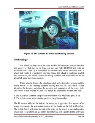
In automotive manufacturing, wheel loading is the process to mount the wheels
onto a car when the production line is moving at random speed. Currently this
process is done by the operators
The demand to automate the wheel loading process is getting higher and higher,
especially when the automotive manufacturing is facing difficult time. There
are many challenges to automate the wheel loading process. When the car is
moving on the production line, it could move along both the X and Y directions
at random speed.
Industrial robots have increased in both number and complexity over the years
for assembly tasks because o flexibility and the increasing requirements of
product quality and quantity. One of the main reasons is that it is difficult for
conventional industrial robots to adjust to any sort of change of the assembly
processes.
Therefore, more intelligent industrial robotic systems have to be developed in
order to perform complex assembly tasks like wheel loading.
Automated Assembly System
Dept of Mechanical Engineering MSRIT, Bangalore Page 14
Figure 13 The current manual wheel loading process
Methodology
The wheel loading station includes a robot with sensors, robot controller
and conveyor that the car is fixed on etc. An ABB IRB6600 rob with an
additional axis (Axis 7) is controlled to automatically mount the wheel onto a
wheel hub while it is randomly moving. Since the wheel is randomly loaded
into the station, the wheel location including position and orientation has to be
identified using the vision system.
If the wheel is found, the wheel is picked up by the robot gripper and the
robot moves to the starting position waiting for the car. the vision system
identifies the location including the position and orientation of the wheel hub.
The wheel is then rotated by Axis 7 to match the orientation of the wheel hub.
1.The IR sensor identifies the position/orientation of a wheel and picks it up
2. The robot moves to the starting position (taught manually).
The IR sensor will give the info to the conveyor triggers the first trigger. After
image processing, the orientation pattern of the bolts on the hub is identified.
The robot Axis 7 will rotate to match the holes on the wheel to the studs on the
wheel hub. To perform an assembly, the robot has to be controlled to approach
Automated Assembly System
Dept of Mechanical Engineering MSRIT, Bangalore Page 15
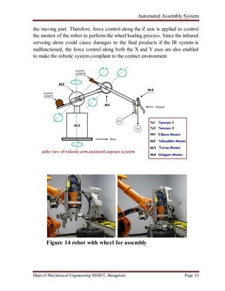
the moving part. Therefore, force control along the Z axis is applied to control
the motion of the robot to perform the wheel loading process. Since the infrared
servoing alone could cause damages to the final products if the IR system is
malfunctioned, the force control along both the X and Y axes are also enabled
to make the robotic system compliant to the contact environment.
Figure 14 robot with wheel for assembly
Automated Assembly System
Dept of Mechanical Engineering MSRIT, Bangalore Page 16
Conclusion
 In this paper, an automated wheel loading system is developed based on
the synergic combination of visual servoing and force control strategy.
 Visual servoing is used to track the 2D motion of the car on the
conveyor. Experiments were performed successfully and the results
demonstrated that the developed technology can be used for wheel
loading.
 Since huge amount of time and resource can be saved using the
developed robotic system, this innovative technology will have great
impact in the automotive industry, especially when automotive
manufacturing is facing difficulties
Automated Assembly System
Dept of Mechanical Engineering MSRIT, Bangalore Page 17
ASSEMBLY LINE PRODUCTION IMPROVEMENT BY
OPTIMIZATION OF CYCLE TIME
1SANDIP K. KUMBHAR, 2NIRANJAN M. R, 3SANJAY T. SATPUTE
Abstract
Automobile manufacturing organizations are currently Facing a necessity to
respond to rapidly changing customer needs, desires and fluctuating market
demand. As customer demand higher quality, shorter delivery time, higher
customer service level and lower prices. organizations must need to develop
new methodologies allowing them to remain competitive and flexible
simultaneously so that they can respond to the new demands This requirement
is focusing on optimization of cycle time, reduction non value added work
Continuous Improvement
Introduction
Production improvement in the any sectors depends on man, machine
,material, methods and management. Cycle time is one of the important data
for the line balancing at and production line. Cycle time is the time it takes to
finish one product Reducing cycle time requires eliminating or reducing non-
value-added activity like repair due to defects, machine set-up, inspection, test
and schedule delays.
 This elimination is done through
1. Process analysis
2. Work analysis
3. Motion analysis
Process analysis is useful to clean, store and maintain the condition. Standard
work and optimize cycle time is possible at best level.
work analysis is useful to study relevant work process and cycle time process
optimization The strength of work analysis is its inherent simplicity. It is the
easiest and fastest method to get started.
motion analysis is key ingredient for properly understanding other topics for
improvement such as standardized work.
Automated Assembly System
Dept of Mechanical Engineering MSRIT, Bangalore Page 18
CASE STUDY
Problem Statement:
In order to achieve highly productive assembly line, the optimum amount of
resources in terms of workstations and labor will need to be determined. One
way to do this is by performing a line balancing study. Line balancing tool can
help to characterize the line capacity and take into account the dynamic
behavior of the system. Line balancing tool also can assist in implementing
changes in a quick and effective manner. It also is able to evaluate and optimize
the line throughput, machine utilization and cycle time. TKAP- R transmission
planned to increase the production capacity from 708/day to 775/day. The main
basic theme is to improve the productivity through elimination of machinery,
material, worker and production methods at transmission line
Methodology:
Assembly production improvement done by analysis study of process
work, motion. As per analysis study of assembly line conclude wastage
Of material, worker and production and optimize cycle time.
Actual model developed in the case study at the stage of safety comfort
work so think of changes can adopt with low cost automation creative think in
chute modification. So the design data is prepare and modification think process
about if the both side weight lifting can be easily handle load and suitable work
constants so from this idea team execute at floor level and fabricate parts newly
Line before condition:
At the stage of before implementation of low cost automation analysis of cycle
time study and tact time of one process required 70sec. there found wastage of
time, non value added work. Production quantity in numbers at 95% line
efficiency at the stage of before implementation is produce 708 units per day.
Automated Assembly System
Dept of Mechanical Engineering MSRIT, Bangalore Page 19
Fig. Assembly line before implementation of LCA
After LCA implemented:
At the stage of after implementation of low cost automation analysis of cycle
time study and tact time of one process required 66sec. Production quantity in
numbers at 95% line efficiency at the stage of after implementation is produce
775 units per day.
This implementation is reduce the wastage of non value added work, line
balancing in standard way and reduces the cost of product with improvement of
production.
Fig. LCA implementation for optimization of cycle time
CONCLUSION
Automated Assembly System
Dept of Mechanical Engineering MSRIT, Bangalore Page 20
 As in this case study the main basic theme was to improve the
productivity through elimination non-value added activity in
transmission line.
 This was obtained by implementing LCA. the productivity was
increased from 706 to770 units/day. the cost of operation is
reduced considerably
References
Automated Assembly System
Dept of Mechanical Engineering MSRIT, Bangalore Page 21
1. Artun Torenli [2009], “Assembly line design and optimization”, Master of
science thesis in the International Masters programme automotive engineering,
Chalmers university Of Technology Goteborg, Sweden.
2. Dr. Jay Baron, Brett C. Smith [2006], “Low-Volume Vehicle
Production by Manufacturing, Engineering and Technology”,Center for
Automotive Research, USA.
3. G Reinhart, J Werner [2009], “Flexible Automation for the
Assembly in Motion”, Institute for Machine Tools.

More Related Content

What's hot

Group Technology
Group TechnologyGroup Technology
Group Technology
Sunith Guraddi
 
Layout of FMS
Layout of FMSLayout of FMS
Layout of FMSsgrsoni45
 
Group technology and cellular manufacturing
Group technology and cellular manufacturingGroup technology and cellular manufacturing
Group technology and cellular manufacturing
Khulna university of engineering and technology
 
Adaptive control System
Adaptive control SystemAdaptive control System
Adaptive control System
SUMIT ATTRI
 
Group technology, Production flow Analysis
Group technology, Production flow AnalysisGroup technology, Production flow Analysis
Group technology, Production flow Analysis
KEERTHIVASAN RAVI
 
Flexible manufacturing systems (FMS)
Flexible manufacturing systems (FMS)Flexible manufacturing systems (FMS)
Flexible manufacturing systems (FMS)
jntuhcej
 
CELLULAR MANUFACTURING & FLEXIBLE MANUFACTURING SYSTEM - UNIT 5 - CAD & M
CELLULAR MANUFACTURING & FLEXIBLE MANUFACTURING SYSTEM - UNIT 5 - CAD & MCELLULAR MANUFACTURING & FLEXIBLE MANUFACTURING SYSTEM - UNIT 5 - CAD & M
CELLULAR MANUFACTURING & FLEXIBLE MANUFACTURING SYSTEM - UNIT 5 - CAD & M
Balamurugan Subburaj
 
Computer aided quality control
Computer aided quality controlComputer aided quality control
Computer aided quality control
Ahmad Bajwa
 
ANALYSIS OF TRANSFER LINE WITH BUFFER STORAGE
ANALYSIS OF TRANSFER LINE WITH BUFFER STORAGEANALYSIS OF TRANSFER LINE WITH BUFFER STORAGE
ANALYSIS OF TRANSFER LINE WITH BUFFER STORAGE
Manoj Gowda K
 
Automated guided vehicle systems (AGVs)
Automated guided vehicle systems (AGVs)Automated guided vehicle systems (AGVs)
Automated guided vehicle systems (AGVs)
RAMCO INSTITUTE OF TECHNOLOGY, RAJAPALAYAM
 
Apt programming
Apt programmingApt programming
Apt programming
Vemulapalli Das
 
Flexible manufacturing system(FMS).
Flexible manufacturing system(FMS).Flexible manufacturing system(FMS).
Flexible manufacturing system(FMS).
Nitin Patil
 
Flexible manufacturing systems (FMS)
Flexible manufacturing systems (FMS)Flexible manufacturing systems (FMS)
Flexible manufacturing systems (FMS)
SERCOD
 
Automated Production Lines
Automated Production LinesAutomated Production Lines
Automated Production Lines
VADLAJAGADEESHWARAAC
 
Automated Assembly Systems
Automated Assembly SystemsAutomated Assembly Systems
Automated Assembly Systems
chethan kumar
 
Aiar. unit ii. transfer lines
Aiar. unit ii. transfer linesAiar. unit ii. transfer lines
Aiar. unit ii. transfer lines
Kunal mane
 
Group Technology
Group TechnologyGroup Technology
Group Technology
Himanshi Gupta
 
Antifriction guideways, feed drives, spindles
Antifriction guideways, feed drives, spindlesAntifriction guideways, feed drives, spindles
Antifriction guideways, feed drives, spindles
vedamsh95
 
Automated storage and retrieval system
Automated storage and retrieval systemAutomated storage and retrieval system
Automated storage and retrieval system
Prasanna3804
 
Single-Station Manufacturing Cells
Single-Station Manufacturing CellsSingle-Station Manufacturing Cells
Single-Station Manufacturing Cells
VADLAJAGADEESHWARAAC
 

What's hot (20)

Group Technology
Group TechnologyGroup Technology
Group Technology
 
Layout of FMS
Layout of FMSLayout of FMS
Layout of FMS
 
Group technology and cellular manufacturing
Group technology and cellular manufacturingGroup technology and cellular manufacturing
Group technology and cellular manufacturing
 
Adaptive control System
Adaptive control SystemAdaptive control System
Adaptive control System
 
Group technology, Production flow Analysis
Group technology, Production flow AnalysisGroup technology, Production flow Analysis
Group technology, Production flow Analysis
 
Flexible manufacturing systems (FMS)
Flexible manufacturing systems (FMS)Flexible manufacturing systems (FMS)
Flexible manufacturing systems (FMS)
 
CELLULAR MANUFACTURING & FLEXIBLE MANUFACTURING SYSTEM - UNIT 5 - CAD & M
CELLULAR MANUFACTURING & FLEXIBLE MANUFACTURING SYSTEM - UNIT 5 - CAD & MCELLULAR MANUFACTURING & FLEXIBLE MANUFACTURING SYSTEM - UNIT 5 - CAD & M
CELLULAR MANUFACTURING & FLEXIBLE MANUFACTURING SYSTEM - UNIT 5 - CAD & M
 
Computer aided quality control
Computer aided quality controlComputer aided quality control
Computer aided quality control
 
ANALYSIS OF TRANSFER LINE WITH BUFFER STORAGE
ANALYSIS OF TRANSFER LINE WITH BUFFER STORAGEANALYSIS OF TRANSFER LINE WITH BUFFER STORAGE
ANALYSIS OF TRANSFER LINE WITH BUFFER STORAGE
 
Automated guided vehicle systems (AGVs)
Automated guided vehicle systems (AGVs)Automated guided vehicle systems (AGVs)
Automated guided vehicle systems (AGVs)
 
Apt programming
Apt programmingApt programming
Apt programming
 
Flexible manufacturing system(FMS).
Flexible manufacturing system(FMS).Flexible manufacturing system(FMS).
Flexible manufacturing system(FMS).
 
Flexible manufacturing systems (FMS)
Flexible manufacturing systems (FMS)Flexible manufacturing systems (FMS)
Flexible manufacturing systems (FMS)
 
Automated Production Lines
Automated Production LinesAutomated Production Lines
Automated Production Lines
 
Automated Assembly Systems
Automated Assembly SystemsAutomated Assembly Systems
Automated Assembly Systems
 
Aiar. unit ii. transfer lines
Aiar. unit ii. transfer linesAiar. unit ii. transfer lines
Aiar. unit ii. transfer lines
 
Group Technology
Group TechnologyGroup Technology
Group Technology
 
Antifriction guideways, feed drives, spindles
Antifriction guideways, feed drives, spindlesAntifriction guideways, feed drives, spindles
Antifriction guideways, feed drives, spindles
 
Automated storage and retrieval system
Automated storage and retrieval systemAutomated storage and retrieval system
Automated storage and retrieval system
 
Single-Station Manufacturing Cells
Single-Station Manufacturing CellsSingle-Station Manufacturing Cells
Single-Station Manufacturing Cells
 

Similar to Automated assembly systems

Unit iii. automated assemby systems
Unit iii.  automated assemby systemsUnit iii.  automated assemby systems
Unit iii. automated assemby systems
Kunal mane
 
automatedassemblysystems-200413091052.pdf
automatedassemblysystems-200413091052.pdfautomatedassemblysystems-200413091052.pdf
automatedassemblysystems-200413091052.pdf
Robin8015873726
 
Automated assembly systems
Automated assembly systemsAutomated assembly systems
Automated assembly systems
kierachen
 
Design for assembly methods
Design for assembly methodsDesign for assembly methods
Design for assembly methods
aman1312
 
Bell-Everman Plug and Play Motion Subsystems
Bell-Everman Plug and Play Motion SubsystemsBell-Everman Plug and Play Motion Subsystems
Bell-Everman Plug and Play Motion Subsystems
Electromate
 
Qavane_211068691__IEEE_Paper-1
Qavane_211068691__IEEE_Paper-1Qavane_211068691__IEEE_Paper-1
Qavane_211068691__IEEE_Paper-1Mandilakhe Qavane
 
02-Chapter_2_Robot_Work_Cell_Design_and_Control_Final.pdf
02-Chapter_2_Robot_Work_Cell_Design_and_Control_Final.pdf02-Chapter_2_Robot_Work_Cell_Design_and_Control_Final.pdf
02-Chapter_2_Robot_Work_Cell_Design_and_Control_Final.pdf
RahbiMalek
 
IRJET- Basic Study of Assembly Line Balancing
IRJET- Basic Study of Assembly Line BalancingIRJET- Basic Study of Assembly Line Balancing
IRJET- Basic Study of Assembly Line Balancing
IRJET Journal
 
IRJET- Design, Development and Manufacturing of Dedicated Fixture for the...
IRJET-  	  Design, Development and Manufacturing of Dedicated Fixture for the...IRJET-  	  Design, Development and Manufacturing of Dedicated Fixture for the...
IRJET- Design, Development and Manufacturing of Dedicated Fixture for the...
IRJET Journal
 
vrushabh sahare part transfer mechanism questions
vrushabh sahare   part transfer mechanism questionsvrushabh sahare   part transfer mechanism questions
vrushabh sahare part transfer mechanism questions
Akash Maurya
 
Automation
AutomationAutomation
Automation
Margi Chokshi
 
How to design a machine?
How to design a machine?How to design a machine?
How to design a machine?
swargpatel283
 
semi automatic puzzle car parking
semi automatic puzzle car parking semi automatic puzzle car parking
semi automatic puzzle car parking
ParikshitSharma37
 
Flexiblemanufacturingsystemss
Flexiblemanufacturingsystemss Flexiblemanufacturingsystemss
Flexiblemanufacturingsystemss satyajit321
 
IRJET- Generation of Alternative Solutions for Differential-Less Drive Sys...
IRJET- 	  Generation of Alternative Solutions for Differential-Less Drive Sys...IRJET- 	  Generation of Alternative Solutions for Differential-Less Drive Sys...
IRJET- Generation of Alternative Solutions for Differential-Less Drive Sys...
IRJET Journal
 
Optimization of automobile active suspension system using minimal order
Optimization of automobile active suspension system using  minimal orderOptimization of automobile active suspension system using  minimal order
Optimization of automobile active suspension system using minimal order
IJECEIAES
 
presentation on Toyota Assembly Unit Simulation
presentation on Toyota Assembly Unit Simulationpresentation on Toyota Assembly Unit Simulation
presentation on Toyota Assembly Unit Simulation
sandeepbags2004
 
Automation of Fixtures Using Hydraulic Power Pack for a Bogie Underframe
Automation of Fixtures Using Hydraulic Power Pack for a Bogie UnderframeAutomation of Fixtures Using Hydraulic Power Pack for a Bogie Underframe
Automation of Fixtures Using Hydraulic Power Pack for a Bogie Underframe
IOSR Journals
 
Design of Multi Link Structure for Rear Suspenion of a Heavy Vehicle
Design of Multi Link Structure for Rear Suspenion of a Heavy VehicleDesign of Multi Link Structure for Rear Suspenion of a Heavy Vehicle
Design of Multi Link Structure for Rear Suspenion of a Heavy Vehicle
theijes
 
Finite Element Based Analysis of Rotating Robot Pedestal
Finite Element Based Analysis of Rotating Robot PedestalFinite Element Based Analysis of Rotating Robot Pedestal
Finite Element Based Analysis of Rotating Robot Pedestal
IRJET Journal
 

Similar to Automated assembly systems (20)

Unit iii. automated assemby systems
Unit iii.  automated assemby systemsUnit iii.  automated assemby systems
Unit iii. automated assemby systems
 
automatedassemblysystems-200413091052.pdf
automatedassemblysystems-200413091052.pdfautomatedassemblysystems-200413091052.pdf
automatedassemblysystems-200413091052.pdf
 
Automated assembly systems
Automated assembly systemsAutomated assembly systems
Automated assembly systems
 
Design for assembly methods
Design for assembly methodsDesign for assembly methods
Design for assembly methods
 
Bell-Everman Plug and Play Motion Subsystems
Bell-Everman Plug and Play Motion SubsystemsBell-Everman Plug and Play Motion Subsystems
Bell-Everman Plug and Play Motion Subsystems
 
Qavane_211068691__IEEE_Paper-1
Qavane_211068691__IEEE_Paper-1Qavane_211068691__IEEE_Paper-1
Qavane_211068691__IEEE_Paper-1
 
02-Chapter_2_Robot_Work_Cell_Design_and_Control_Final.pdf
02-Chapter_2_Robot_Work_Cell_Design_and_Control_Final.pdf02-Chapter_2_Robot_Work_Cell_Design_and_Control_Final.pdf
02-Chapter_2_Robot_Work_Cell_Design_and_Control_Final.pdf
 
IRJET- Basic Study of Assembly Line Balancing
IRJET- Basic Study of Assembly Line BalancingIRJET- Basic Study of Assembly Line Balancing
IRJET- Basic Study of Assembly Line Balancing
 
IRJET- Design, Development and Manufacturing of Dedicated Fixture for the...
IRJET-  	  Design, Development and Manufacturing of Dedicated Fixture for the...IRJET-  	  Design, Development and Manufacturing of Dedicated Fixture for the...
IRJET- Design, Development and Manufacturing of Dedicated Fixture for the...
 
vrushabh sahare part transfer mechanism questions
vrushabh sahare   part transfer mechanism questionsvrushabh sahare   part transfer mechanism questions
vrushabh sahare part transfer mechanism questions
 
Automation
AutomationAutomation
Automation
 
How to design a machine?
How to design a machine?How to design a machine?
How to design a machine?
 
semi automatic puzzle car parking
semi automatic puzzle car parking semi automatic puzzle car parking
semi automatic puzzle car parking
 
Flexiblemanufacturingsystemss
Flexiblemanufacturingsystemss Flexiblemanufacturingsystemss
Flexiblemanufacturingsystemss
 
IRJET- Generation of Alternative Solutions for Differential-Less Drive Sys...
IRJET- 	  Generation of Alternative Solutions for Differential-Less Drive Sys...IRJET- 	  Generation of Alternative Solutions for Differential-Less Drive Sys...
IRJET- Generation of Alternative Solutions for Differential-Less Drive Sys...
 
Optimization of automobile active suspension system using minimal order
Optimization of automobile active suspension system using  minimal orderOptimization of automobile active suspension system using  minimal order
Optimization of automobile active suspension system using minimal order
 
presentation on Toyota Assembly Unit Simulation
presentation on Toyota Assembly Unit Simulationpresentation on Toyota Assembly Unit Simulation
presentation on Toyota Assembly Unit Simulation
 
Automation of Fixtures Using Hydraulic Power Pack for a Bogie Underframe
Automation of Fixtures Using Hydraulic Power Pack for a Bogie UnderframeAutomation of Fixtures Using Hydraulic Power Pack for a Bogie Underframe
Automation of Fixtures Using Hydraulic Power Pack for a Bogie Underframe
 
Design of Multi Link Structure for Rear Suspenion of a Heavy Vehicle
Design of Multi Link Structure for Rear Suspenion of a Heavy VehicleDesign of Multi Link Structure for Rear Suspenion of a Heavy Vehicle
Design of Multi Link Structure for Rear Suspenion of a Heavy Vehicle
 
Finite Element Based Analysis of Rotating Robot Pedestal
Finite Element Based Analysis of Rotating Robot PedestalFinite Element Based Analysis of Rotating Robot Pedestal
Finite Element Based Analysis of Rotating Robot Pedestal
 

Recently uploaded

Essentials of Automations: Optimizing FME Workflows with Parameters
Essentials of Automations: Optimizing FME Workflows with ParametersEssentials of Automations: Optimizing FME Workflows with Parameters
Essentials of Automations: Optimizing FME Workflows with Parameters
Safe Software
 
FIDO Alliance Osaka Seminar: The WebAuthn API and Discoverable Credentials.pdf
FIDO Alliance Osaka Seminar: The WebAuthn API and Discoverable Credentials.pdfFIDO Alliance Osaka Seminar: The WebAuthn API and Discoverable Credentials.pdf
FIDO Alliance Osaka Seminar: The WebAuthn API and Discoverable Credentials.pdf
FIDO Alliance
 
De-mystifying Zero to One: Design Informed Techniques for Greenfield Innovati...
De-mystifying Zero to One: Design Informed Techniques for Greenfield Innovati...De-mystifying Zero to One: Design Informed Techniques for Greenfield Innovati...
De-mystifying Zero to One: Design Informed Techniques for Greenfield Innovati...
Product School
 
FIDO Alliance Osaka Seminar: Passkeys at Amazon.pdf
FIDO Alliance Osaka Seminar: Passkeys at Amazon.pdfFIDO Alliance Osaka Seminar: Passkeys at Amazon.pdf
FIDO Alliance Osaka Seminar: Passkeys at Amazon.pdf
FIDO Alliance
 
GenAISummit 2024 May 28 Sri Ambati Keynote: AGI Belongs to The Community in O...
GenAISummit 2024 May 28 Sri Ambati Keynote: AGI Belongs to The Community in O...GenAISummit 2024 May 28 Sri Ambati Keynote: AGI Belongs to The Community in O...
GenAISummit 2024 May 28 Sri Ambati Keynote: AGI Belongs to The Community in O...
Sri Ambati
 
Knowledge engineering: from people to machines and back
Knowledge engineering: from people to machines and backKnowledge engineering: from people to machines and back
Knowledge engineering: from people to machines and back
Elena Simperl
 
The Future of Platform Engineering
The Future of Platform EngineeringThe Future of Platform Engineering
The Future of Platform Engineering
Jemma Hussein Allen
 
Designing Great Products: The Power of Design and Leadership by Chief Designe...
Designing Great Products: The Power of Design and Leadership by Chief Designe...Designing Great Products: The Power of Design and Leadership by Chief Designe...
Designing Great Products: The Power of Design and Leadership by Chief Designe...
Product School
 
Dev Dives: Train smarter, not harder – active learning and UiPath LLMs for do...
Dev Dives: Train smarter, not harder – active learning and UiPath LLMs for do...Dev Dives: Train smarter, not harder – active learning and UiPath LLMs for do...
Dev Dives: Train smarter, not harder – active learning and UiPath LLMs for do...
UiPathCommunity
 
Bits & Pixels using AI for Good.........
Bits & Pixels using AI for Good.........Bits & Pixels using AI for Good.........
Bits & Pixels using AI for Good.........
Alison B. Lowndes
 
Neuro-symbolic is not enough, we need neuro-*semantic*
Neuro-symbolic is not enough, we need neuro-*semantic*Neuro-symbolic is not enough, we need neuro-*semantic*
Neuro-symbolic is not enough, we need neuro-*semantic*
Frank van Harmelen
 
FIDO Alliance Osaka Seminar: Passkeys and the Road Ahead.pdf
FIDO Alliance Osaka Seminar: Passkeys and the Road Ahead.pdfFIDO Alliance Osaka Seminar: Passkeys and the Road Ahead.pdf
FIDO Alliance Osaka Seminar: Passkeys and the Road Ahead.pdf
FIDO Alliance
 
The Art of the Pitch: WordPress Relationships and Sales
The Art of the Pitch: WordPress Relationships and SalesThe Art of the Pitch: WordPress Relationships and Sales
The Art of the Pitch: WordPress Relationships and Sales
Laura Byrne
 
JMeter webinar - integration with InfluxDB and Grafana
JMeter webinar - integration with InfluxDB and GrafanaJMeter webinar - integration with InfluxDB and Grafana
JMeter webinar - integration with InfluxDB and Grafana
RTTS
 
Transcript: Selling digital books in 2024: Insights from industry leaders - T...
Transcript: Selling digital books in 2024: Insights from industry leaders - T...Transcript: Selling digital books in 2024: Insights from industry leaders - T...
Transcript: Selling digital books in 2024: Insights from industry leaders - T...
BookNet Canada
 
Key Trends Shaping the Future of Infrastructure.pdf
Key Trends Shaping the Future of Infrastructure.pdfKey Trends Shaping the Future of Infrastructure.pdf
Key Trends Shaping the Future of Infrastructure.pdf
Cheryl Hung
 
Accelerate your Kubernetes clusters with Varnish Caching
Accelerate your Kubernetes clusters with Varnish CachingAccelerate your Kubernetes clusters with Varnish Caching
Accelerate your Kubernetes clusters with Varnish Caching
Thijs Feryn
 
GDG Cloud Southlake #33: Boule & Rebala: Effective AppSec in SDLC using Deplo...
GDG Cloud Southlake #33: Boule & Rebala: Effective AppSec in SDLC using Deplo...GDG Cloud Southlake #33: Boule & Rebala: Effective AppSec in SDLC using Deplo...
GDG Cloud Southlake #33: Boule & Rebala: Effective AppSec in SDLC using Deplo...
James Anderson
 
When stars align: studies in data quality, knowledge graphs, and machine lear...
When stars align: studies in data quality, knowledge graphs, and machine lear...When stars align: studies in data quality, knowledge graphs, and machine lear...
When stars align: studies in data quality, knowledge graphs, and machine lear...
Elena Simperl
 
FIDO Alliance Osaka Seminar: Overview.pdf
FIDO Alliance Osaka Seminar: Overview.pdfFIDO Alliance Osaka Seminar: Overview.pdf
FIDO Alliance Osaka Seminar: Overview.pdf
FIDO Alliance
 

Recently uploaded (20)

Essentials of Automations: Optimizing FME Workflows with Parameters
Essentials of Automations: Optimizing FME Workflows with ParametersEssentials of Automations: Optimizing FME Workflows with Parameters
Essentials of Automations: Optimizing FME Workflows with Parameters
 
FIDO Alliance Osaka Seminar: The WebAuthn API and Discoverable Credentials.pdf
FIDO Alliance Osaka Seminar: The WebAuthn API and Discoverable Credentials.pdfFIDO Alliance Osaka Seminar: The WebAuthn API and Discoverable Credentials.pdf
FIDO Alliance Osaka Seminar: The WebAuthn API and Discoverable Credentials.pdf
 
De-mystifying Zero to One: Design Informed Techniques for Greenfield Innovati...
De-mystifying Zero to One: Design Informed Techniques for Greenfield Innovati...De-mystifying Zero to One: Design Informed Techniques for Greenfield Innovati...
De-mystifying Zero to One: Design Informed Techniques for Greenfield Innovati...
 
FIDO Alliance Osaka Seminar: Passkeys at Amazon.pdf
FIDO Alliance Osaka Seminar: Passkeys at Amazon.pdfFIDO Alliance Osaka Seminar: Passkeys at Amazon.pdf
FIDO Alliance Osaka Seminar: Passkeys at Amazon.pdf
 
GenAISummit 2024 May 28 Sri Ambati Keynote: AGI Belongs to The Community in O...
GenAISummit 2024 May 28 Sri Ambati Keynote: AGI Belongs to The Community in O...GenAISummit 2024 May 28 Sri Ambati Keynote: AGI Belongs to The Community in O...
GenAISummit 2024 May 28 Sri Ambati Keynote: AGI Belongs to The Community in O...
 
Knowledge engineering: from people to machines and back
Knowledge engineering: from people to machines and backKnowledge engineering: from people to machines and back
Knowledge engineering: from people to machines and back
 
The Future of Platform Engineering
The Future of Platform EngineeringThe Future of Platform Engineering
The Future of Platform Engineering
 
Designing Great Products: The Power of Design and Leadership by Chief Designe...
Designing Great Products: The Power of Design and Leadership by Chief Designe...Designing Great Products: The Power of Design and Leadership by Chief Designe...
Designing Great Products: The Power of Design and Leadership by Chief Designe...
 
Dev Dives: Train smarter, not harder – active learning and UiPath LLMs for do...
Dev Dives: Train smarter, not harder – active learning and UiPath LLMs for do...Dev Dives: Train smarter, not harder – active learning and UiPath LLMs for do...
Dev Dives: Train smarter, not harder – active learning and UiPath LLMs for do...
 
Bits & Pixels using AI for Good.........
Bits & Pixels using AI for Good.........Bits & Pixels using AI for Good.........
Bits & Pixels using AI for Good.........
 
Neuro-symbolic is not enough, we need neuro-*semantic*
Neuro-symbolic is not enough, we need neuro-*semantic*Neuro-symbolic is not enough, we need neuro-*semantic*
Neuro-symbolic is not enough, we need neuro-*semantic*
 
FIDO Alliance Osaka Seminar: Passkeys and the Road Ahead.pdf
FIDO Alliance Osaka Seminar: Passkeys and the Road Ahead.pdfFIDO Alliance Osaka Seminar: Passkeys and the Road Ahead.pdf
FIDO Alliance Osaka Seminar: Passkeys and the Road Ahead.pdf
 
The Art of the Pitch: WordPress Relationships and Sales
The Art of the Pitch: WordPress Relationships and SalesThe Art of the Pitch: WordPress Relationships and Sales
The Art of the Pitch: WordPress Relationships and Sales
 
JMeter webinar - integration with InfluxDB and Grafana
JMeter webinar - integration with InfluxDB and GrafanaJMeter webinar - integration with InfluxDB and Grafana
JMeter webinar - integration with InfluxDB and Grafana
 
Transcript: Selling digital books in 2024: Insights from industry leaders - T...
Transcript: Selling digital books in 2024: Insights from industry leaders - T...Transcript: Selling digital books in 2024: Insights from industry leaders - T...
Transcript: Selling digital books in 2024: Insights from industry leaders - T...
 
Key Trends Shaping the Future of Infrastructure.pdf
Key Trends Shaping the Future of Infrastructure.pdfKey Trends Shaping the Future of Infrastructure.pdf
Key Trends Shaping the Future of Infrastructure.pdf
 
Accelerate your Kubernetes clusters with Varnish Caching
Accelerate your Kubernetes clusters with Varnish CachingAccelerate your Kubernetes clusters with Varnish Caching
Accelerate your Kubernetes clusters with Varnish Caching
 
GDG Cloud Southlake #33: Boule & Rebala: Effective AppSec in SDLC using Deplo...
GDG Cloud Southlake #33: Boule & Rebala: Effective AppSec in SDLC using Deplo...GDG Cloud Southlake #33: Boule & Rebala: Effective AppSec in SDLC using Deplo...
GDG Cloud Southlake #33: Boule & Rebala: Effective AppSec in SDLC using Deplo...
 
When stars align: studies in data quality, knowledge graphs, and machine lear...
When stars align: studies in data quality, knowledge graphs, and machine lear...When stars align: studies in data quality, knowledge graphs, and machine lear...
When stars align: studies in data quality, knowledge graphs, and machine lear...
 
FIDO Alliance Osaka Seminar: Overview.pdf
FIDO Alliance Osaka Seminar: Overview.pdfFIDO Alliance Osaka Seminar: Overview.pdf
FIDO Alliance Osaka Seminar: Overview.pdf
 

Automated assembly systems

  • 1. Automated Assembly System Dept of Mechanical Engineering MSRIT, Bangalore Page 1 Automated Assembly Systems Introduction Assembly involves the joining together of two or more separate parts to form new entity which may be assembly or subassembly. Automated assembly refers to the use of mechanized and automated devices to perform the various functions in an assembly line or cell. Automated assembly system performs a sequence of automated operations to combine multiple components in to a single entity which can be a final product or sub assembly. Automated assembly technology should be considered when the following condition exists.  High product demand  Stable product design  The assembly consists of no more than a limited number of components.  The product is designed for automated assembly. Automated assembly system involves less investment compared to transfer lines because 1. Work part produced are smaller in size compared to transfer lines. 2. Assembly operations do not have the large mechanical forces and power requirement 3. Size is very less compared to transfer lines.
  • 2. Automated Assembly System Dept of Mechanical Engineering MSRIT, Bangalore Page 2 DESIGNS FOR AUTOMATED ASSEMBLY Recommendations and principles that can be applied in product design to facilitate automated assembly Reduce the amount of assembly required: This principle can be realized during design by combining functions within the same part that were previously accomplished by separate components in the product. The use of plastic molded parts to substitute for sheet metal parts is an example of this principle. A more complex geometry molded into a plastic part might replace several metal parts. Although the plastic part may seem to be more costly, the savings-in assembly time probably justify the substitution in many cases. Use modular design: In automated assembly, increasing the number of separate assembly steps that are done by a single automated system will result in an increase in the downtime of the system. To reduce this effect, Riley suggests that the design of the product be modular, with perhaps each module requiring a maximum of 12 or 13 parts to be assembled on a single assembly system. Also, the subassembly should be designed around a base part to which other components are added. Reduce the number of fasteners required: Instead of using separate screws and nuts, and similar fasteners, design the fastening mechanism into the component design using snap fits and similar features. Also, design the product modules so that several components are fastened simultaneously rather than each component fastened separately.
  • 3. Automated Assembly System Dept of Mechanical Engineering MSRIT, Bangalore Page 3 Reduce the need for multiple components to lie handled at once: The preferred practice in automated assembly machine design is to separate the operations at different stations rather than to handle and fasten multiple components simultaneously at the same workstation. (It should be noted that robotics technology is causing a rethinking of this practice since robots can be programmed to perform more complex assembly tasks than a single station in a mechanized assembly system. Limit the required directions of access: This principle simply means that the number of directions in which new components are added to the existing subassembly should be minimized. If all of the components can be added vertically from above, this is the ideal situation. Obviously, the design of the subassembly module determines this. Require high quality in components: High performance of the automated assembly system requires consistently good quality of the components that are added at each workstation. Poor-quality components cause jams in the feeding and assembly mechanisms which cause downtime in the automated system. Implement hopperability: This is a term that is used to identify the ease with which a given component can be fed and oriented reliably for delivery from the parts hopper to the assembly workhead.
  • 4. Automated Assembly System Dept of Mechanical Engineering MSRIT, Bangalore Page 4 TYPES OF AUTOMATED ASSEMBLY SYSTEMS Based on the type of work transfer system that is used in the assembly system: • Continuous transfer system • Synchronous transfer system • Asynchronous transfer system • Stationary base part system The first three types involve the same methods of workpart transport described in automated flow line. In the stationary base part system, the base part to which the other components are added is placed in a fixed location, where it remains during the assembly work. Based on physical configuration: • Dial-type assembly machine • In-line assembly machine • Carousel assembly system • Single-station assembly machine The dial-type machine, the base partare indexed around a circular table or dial. The workstations are stationary and usually located around the outside periphery of the dial. The parts ride on the rotating table and arc registered or positioned, in turn, at each station a new component is added to base part. This type of equipment is often referred to as an indexing machine or dial index machine and the configuration is shown in Figure 1 and example of six station rotary shown in figure 2.
  • 5. Automated Assembly System Dept of Mechanical Engineering MSRIT, Bangalore Page 5 Figure 1 Rotary configuration Figure 2 Example of 6 station rotary configuration for assembly In-line type configuration The in-line configuration assembly system consists of a sequence of workstations in abmore-or-less straight-line arrangement as shown in figure 3. An example of an in-line transfer machine used for metal- cutting operations is illustrated in Figure 4. The in-line assembly machine consists of a series of automatic workstations located along an in-line transfer system. It is the automated version of the manual
  • 6. Automated Assembly System Dept of Mechanical Engineering MSRIT, Bangalore Page 6 assembly line. Continuous, synchronous, or asynchronous transfer systems can be used with the in-line configuration. Figure 4 Example of 20 stations In-line configuration
  • 7. Automated Assembly System Dept of Mechanical Engineering MSRIT, Bangalore Page 7 Segmented In-line type The segmented in-line configuration consists of two or more straight- line arrangement which are usually perpendicular to each other with L-Shaped or U-shaped or Rectangular shaped as shown in figure 5-7. The flow of work can take a few 90° turns, either for workpieces reorientation, factory layout limitations, or other reasons, and still qualify as a straight-line configuration. Figure 5 L-shaped configuration Figure 6 U-shaped configuration
  • 8. Automated Assembly System Dept of Mechanical Engineering MSRIT, Bangalore Page 8 Figure 7 Rectangular-shaped configuration Carousel assembly system It represents a hybrid between the circular flow of work provided by the dial assembly machine and straight work flow of the in-line. It is as shown in the figure 8 Figure 8 configuration of a carrousel assembly system
  • 9. Automated Assembly System Dept of Mechanical Engineering MSRIT, Bangalore Page 9 Single- station assembly machine In the single-station assembly machine, the assembly operations are performed at a single location (stationary base part system) as shown in figure 9. The typical operation involves the placement of the base part at the workstation where various components are added to the base. The components are delivered to the station by feeding mechanisms, and one or more workheads perform the various assembly and fastening operations. Figure 9 single-station assembly machine PARTS FEEDING DEVICES In each of the configurations described above, a means of delivering the components to the assembly workhead must be designed. In this section we discuss these devices and their operation. Elements of the parts delivery system The hardware system that delivers components to the workhead in an automated assembly system typically consists of the following elements as shown in figure 10:
  • 10. Automated Assembly System Dept of Mechanical Engineering MSRIT, Bangalore Page 10 Hopper: This is the container into which the components are loaded at the workstation. A separate hopper is used for each component type. The components are usually loaded into the hopper in bulk. This means that the parts are randomly oriented initially in the hopper. Parts feeder: This is a mechanism that removes the components from the hopper one at a time for delivery to the assembly workhead. The hopper and parts feeder are often combined into one operating mechanism. The vibratory bowl feeder, pictured in Figure 11, is a very common example of the hopper-feeder combination. Figure 10 elements of part delivery system Selector and/or orienteer: These elements of the delivery system establish the proper orientation of the components for the assembly workhead. A selector is a device that acts as a filter, permitting only parts that are in the correct orientation to pass through. Components that are not properly oriented are rejected back into the hopper. An orientor is a device that allows properly oriented pans to pass through
  • 11. Automated Assembly System Dept of Mechanical Engineering MSRIT, Bangalore Page 11 but provides a reorientation of components that are not properly oriented initially. Several selector and orientor schemes are illustrated in Figure 12. Selector and orientor devices are often combined and incorporated into one hopper-feeder system. Figure 11 vibratory bowl feeder Figure 12 selector (a) and orientor (b)
  • 12. Automated Assembly System Dept of Mechanical Engineering MSRIT, Bangalore Page 12 Feed track: The preceding elements of the delivery system are usually located some distance from the assembly workhead. A feed track is used to transfer the components from the hopper and parts feeder to the location of the assembly workhead, maintaining proper orientation of the parts during the transfer. There are two general categories of feed tracks: gravity and powered. The gravity feed track is most common. In this type the hopper and parts feeder are located at an elevation that is above the elevation of the workhead. The force of gravity is used to deliver the components to the workhead. The powered feed track uses vibratory action, air pressure, or other means to force the parts to travel along the feed track toward the assembly workhead. Escapement and placement device: The purpose of the escapement device is to remove components from the feed track at time intervals that are consistent with the cycle time of the assembly workhead. The placement device physically places the component in the correct location at the workstation for the assembly operation by the workhead. Several types of escapement and placement devices are
  • 13. Automated Assembly System Dept of Mechanical Engineering MSRIT, Bangalore Page 13 Automated Wheel Assembly System Using PLC J. Dilipsingh1, S. Jeyanthi2, R. S. Jagadeesh3 Abstract- The current process of mounting a wheel in an automotive industry is done by manually which is difficult and time consuming .In order to overcome this problem automated wheel assembly system with PLC is used to reduce human effort, time and energy . The continuous work is done with the robot accurately. Here the camera is replaced by the IR sensor which the price is drastically reduced and equals the same work. Introduction In automotive manufacturing, wheel loading is the process to mount the wheels onto a car when the production line is moving at random speed. Currently this process is done by the operators The demand to automate the wheel loading process is getting higher and higher, especially when the automotive manufacturing is facing difficult time. There are many challenges to automate the wheel loading process. When the car is moving on the production line, it could move along both the X and Y directions at random speed. Industrial robots have increased in both number and complexity over the years for assembly tasks because o flexibility and the increasing requirements of product quality and quantity. One of the main reasons is that it is difficult for conventional industrial robots to adjust to any sort of change of the assembly processes. Therefore, more intelligent industrial robotic systems have to be developed in order to perform complex assembly tasks like wheel loading.
  • 14. Automated Assembly System Dept of Mechanical Engineering MSRIT, Bangalore Page 14 Figure 13 The current manual wheel loading process Methodology The wheel loading station includes a robot with sensors, robot controller and conveyor that the car is fixed on etc. An ABB IRB6600 rob with an additional axis (Axis 7) is controlled to automatically mount the wheel onto a wheel hub while it is randomly moving. Since the wheel is randomly loaded into the station, the wheel location including position and orientation has to be identified using the vision system. If the wheel is found, the wheel is picked up by the robot gripper and the robot moves to the starting position waiting for the car. the vision system identifies the location including the position and orientation of the wheel hub. The wheel is then rotated by Axis 7 to match the orientation of the wheel hub. 1.The IR sensor identifies the position/orientation of a wheel and picks it up 2. The robot moves to the starting position (taught manually). The IR sensor will give the info to the conveyor triggers the first trigger. After image processing, the orientation pattern of the bolts on the hub is identified. The robot Axis 7 will rotate to match the holes on the wheel to the studs on the wheel hub. To perform an assembly, the robot has to be controlled to approach
  • 15. Automated Assembly System Dept of Mechanical Engineering MSRIT, Bangalore Page 15 the moving part. Therefore, force control along the Z axis is applied to control the motion of the robot to perform the wheel loading process. Since the infrared servoing alone could cause damages to the final products if the IR system is malfunctioned, the force control along both the X and Y axes are also enabled to make the robotic system compliant to the contact environment. Figure 14 robot with wheel for assembly
  • 16. Automated Assembly System Dept of Mechanical Engineering MSRIT, Bangalore Page 16 Conclusion  In this paper, an automated wheel loading system is developed based on the synergic combination of visual servoing and force control strategy.  Visual servoing is used to track the 2D motion of the car on the conveyor. Experiments were performed successfully and the results demonstrated that the developed technology can be used for wheel loading.  Since huge amount of time and resource can be saved using the developed robotic system, this innovative technology will have great impact in the automotive industry, especially when automotive manufacturing is facing difficulties
  • 17. Automated Assembly System Dept of Mechanical Engineering MSRIT, Bangalore Page 17 ASSEMBLY LINE PRODUCTION IMPROVEMENT BY OPTIMIZATION OF CYCLE TIME 1SANDIP K. KUMBHAR, 2NIRANJAN M. R, 3SANJAY T. SATPUTE Abstract Automobile manufacturing organizations are currently Facing a necessity to respond to rapidly changing customer needs, desires and fluctuating market demand. As customer demand higher quality, shorter delivery time, higher customer service level and lower prices. organizations must need to develop new methodologies allowing them to remain competitive and flexible simultaneously so that they can respond to the new demands This requirement is focusing on optimization of cycle time, reduction non value added work Continuous Improvement Introduction Production improvement in the any sectors depends on man, machine ,material, methods and management. Cycle time is one of the important data for the line balancing at and production line. Cycle time is the time it takes to finish one product Reducing cycle time requires eliminating or reducing non- value-added activity like repair due to defects, machine set-up, inspection, test and schedule delays.  This elimination is done through 1. Process analysis 2. Work analysis 3. Motion analysis Process analysis is useful to clean, store and maintain the condition. Standard work and optimize cycle time is possible at best level. work analysis is useful to study relevant work process and cycle time process optimization The strength of work analysis is its inherent simplicity. It is the easiest and fastest method to get started. motion analysis is key ingredient for properly understanding other topics for improvement such as standardized work.
  • 18. Automated Assembly System Dept of Mechanical Engineering MSRIT, Bangalore Page 18 CASE STUDY Problem Statement: In order to achieve highly productive assembly line, the optimum amount of resources in terms of workstations and labor will need to be determined. One way to do this is by performing a line balancing study. Line balancing tool can help to characterize the line capacity and take into account the dynamic behavior of the system. Line balancing tool also can assist in implementing changes in a quick and effective manner. It also is able to evaluate and optimize the line throughput, machine utilization and cycle time. TKAP- R transmission planned to increase the production capacity from 708/day to 775/day. The main basic theme is to improve the productivity through elimination of machinery, material, worker and production methods at transmission line Methodology: Assembly production improvement done by analysis study of process work, motion. As per analysis study of assembly line conclude wastage Of material, worker and production and optimize cycle time. Actual model developed in the case study at the stage of safety comfort work so think of changes can adopt with low cost automation creative think in chute modification. So the design data is prepare and modification think process about if the both side weight lifting can be easily handle load and suitable work constants so from this idea team execute at floor level and fabricate parts newly Line before condition: At the stage of before implementation of low cost automation analysis of cycle time study and tact time of one process required 70sec. there found wastage of time, non value added work. Production quantity in numbers at 95% line efficiency at the stage of before implementation is produce 708 units per day.
  • 19. Automated Assembly System Dept of Mechanical Engineering MSRIT, Bangalore Page 19 Fig. Assembly line before implementation of LCA After LCA implemented: At the stage of after implementation of low cost automation analysis of cycle time study and tact time of one process required 66sec. Production quantity in numbers at 95% line efficiency at the stage of after implementation is produce 775 units per day. This implementation is reduce the wastage of non value added work, line balancing in standard way and reduces the cost of product with improvement of production. Fig. LCA implementation for optimization of cycle time CONCLUSION
  • 20. Automated Assembly System Dept of Mechanical Engineering MSRIT, Bangalore Page 20  As in this case study the main basic theme was to improve the productivity through elimination non-value added activity in transmission line.  This was obtained by implementing LCA. the productivity was increased from 706 to770 units/day. the cost of operation is reduced considerably References
  • 21. Automated Assembly System Dept of Mechanical Engineering MSRIT, Bangalore Page 21 1. Artun Torenli [2009], “Assembly line design and optimization”, Master of science thesis in the International Masters programme automotive engineering, Chalmers university Of Technology Goteborg, Sweden. 2. Dr. Jay Baron, Brett C. Smith [2006], “Low-Volume Vehicle Production by Manufacturing, Engineering and Technology”,Center for Automotive Research, USA. 3. G Reinhart, J Werner [2009], “Flexible Automation for the Assembly in Motion”, Institute for Machine Tools.