Download as PDF, PPTX


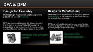
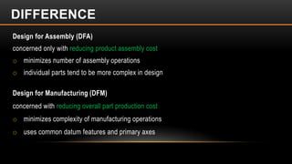
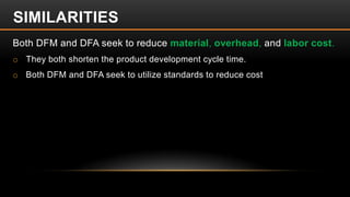
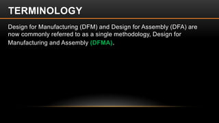
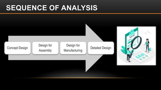
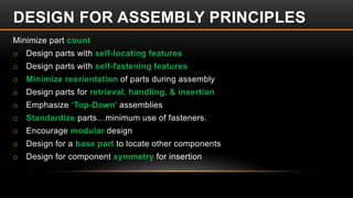
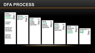
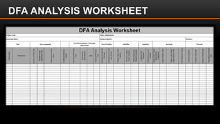
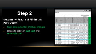
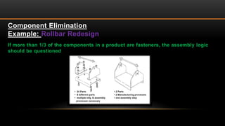
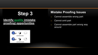
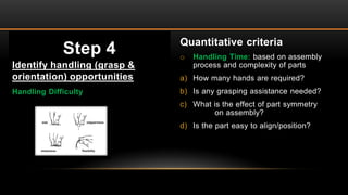
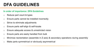
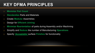


This document provides an overview of Design for Assembly (DFA) techniques. It defines DFA as designing products for ease of assembly to minimize assembly costs. The document outlines the objectives and differences between DFA and Design for Manufacturing (DFM). It then describes the DFA process, which involves analyzing a product's design to minimize part count, simplify handling and insertion of parts, and reduce secondary operations. Guidelines are provided for applying DFA principles to optimize a product's design for assembly.