Download to read offline
![15
REFERENCES
[1] Y. I. Ryu, D. O. Kang, S. J. Heo, H. J. Yim and J. I. Jeon - “Development of analytical
process to reduce side load in strut-type suspension”, Springer Journal.
[2] Thomas Wunshe, Karl Bierker and Karl-Heinz Muhr - “Side load springs as a solution
to minimize adverse side load acting on McPherson Struct , SAE International.
[3] Yang Moucun, Nie Hong - “Analysis approach to durability based on material initial
fatigue quality and S-N curve”, Elsevier Journal
[4] Satoshi Suzuki, Syujii Kamlya and Toshiyuki Imaizumi - “Approached to minimizing
the Side Force of Helical Coil Springs for Riding comfort” , SAE Technical Paper Series
[5] Amol H. Joshi & Harvinder singh Chhabra, “Mathematical Model to Find Piercing
Point in McPherson Strut Suspension and Design of profile for Side Force Control
Spring” - SAE International, 2012](https://image.slidesharecdn.com/sivaprojectphase1-210204120718/75/Design-and-Analysis-of-Side-Force-Spring-in-McPherson-Strut-PHASE-1-15-2048.jpg)

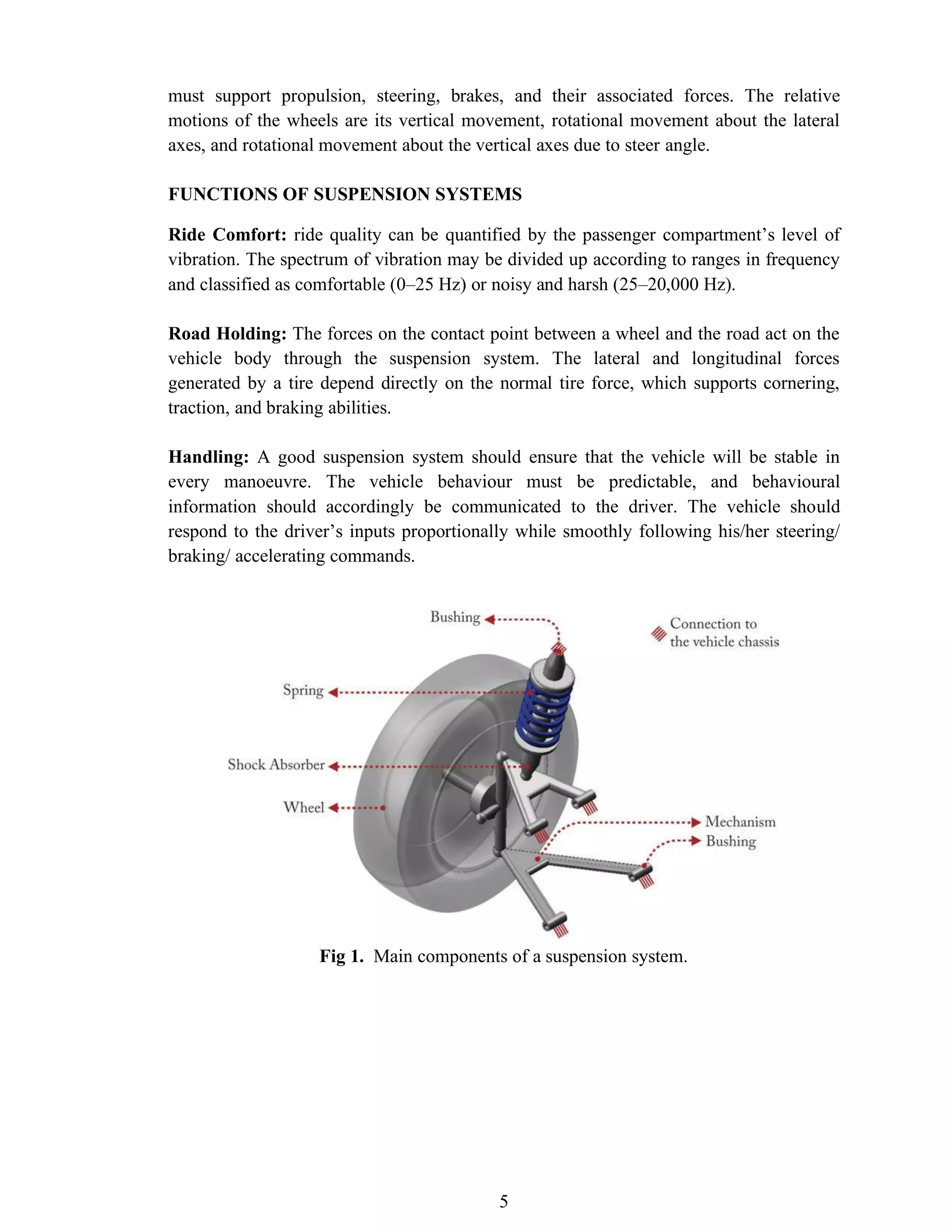
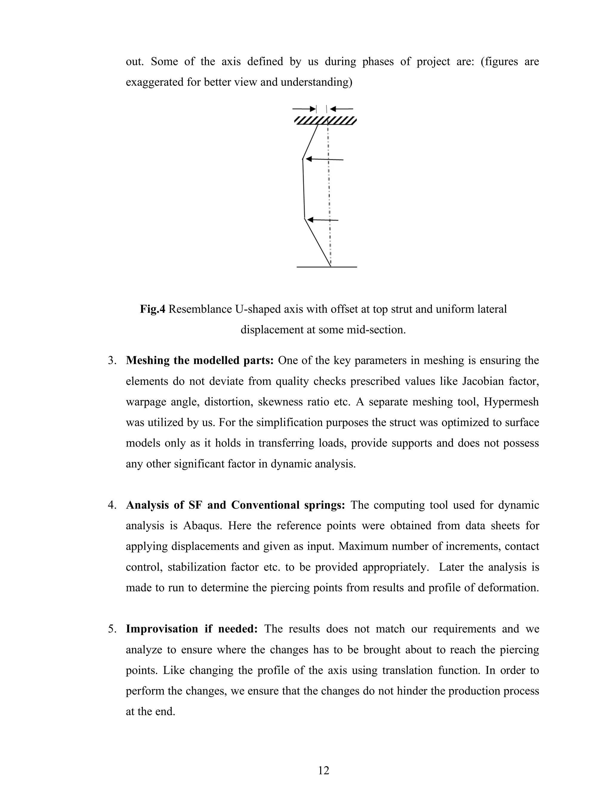
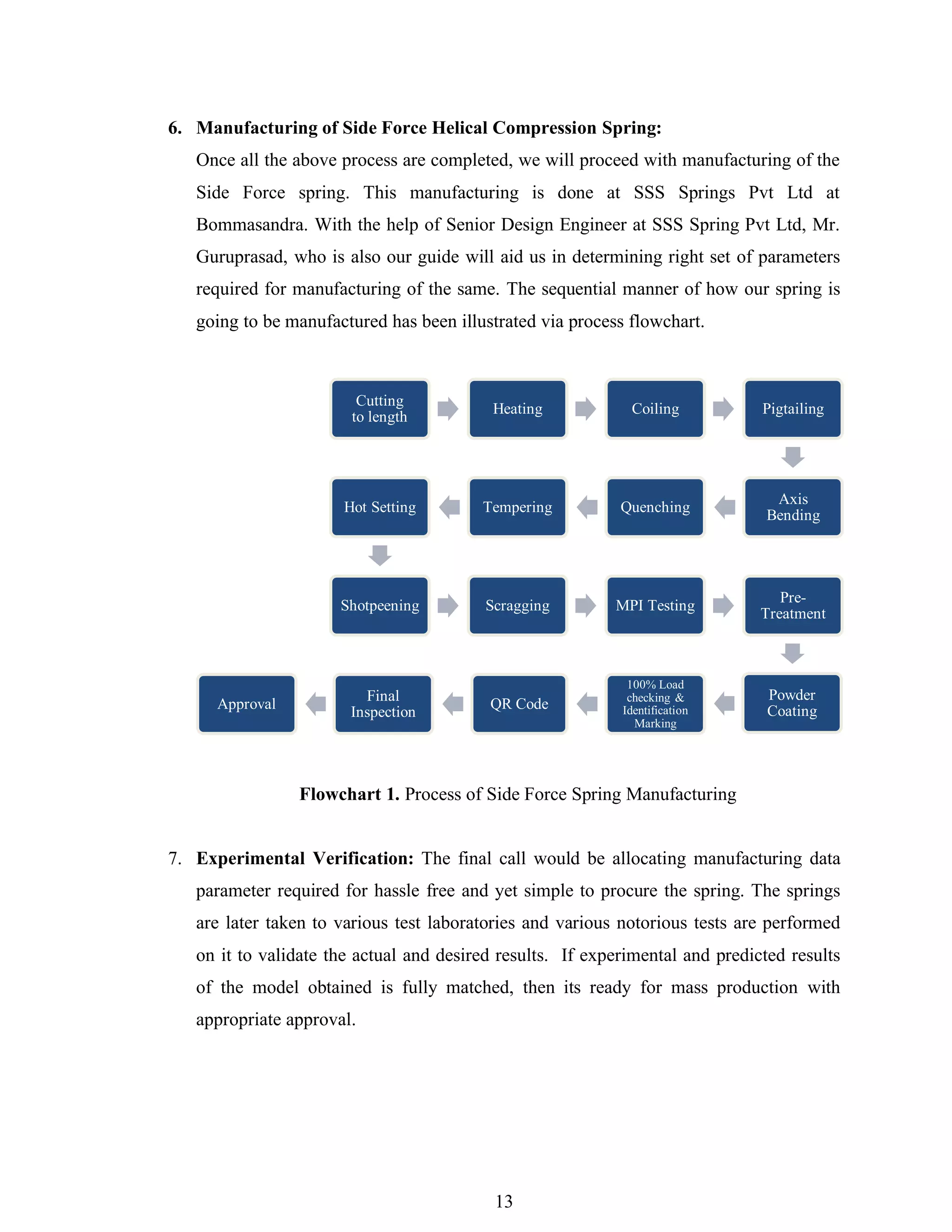
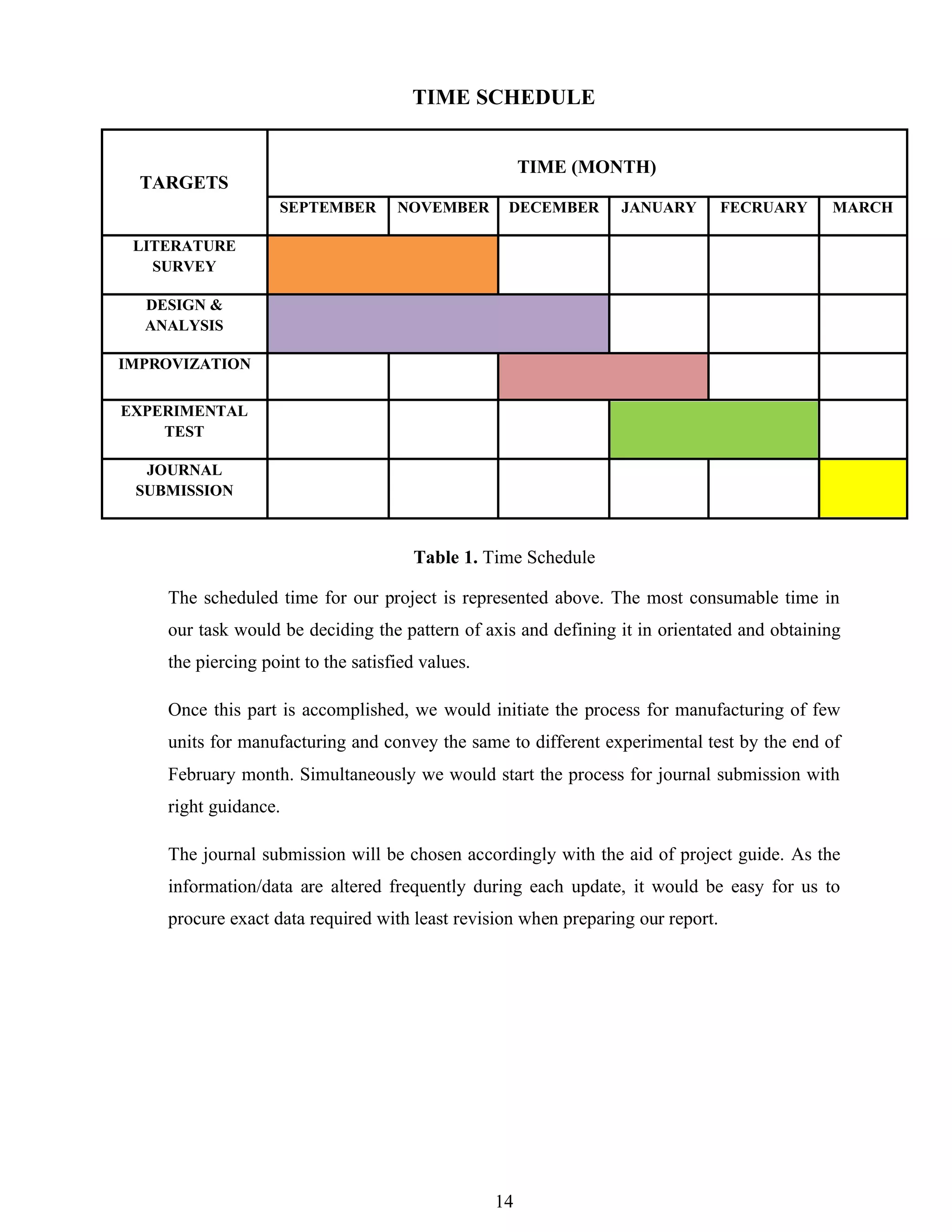
The document is a project phase-I report on the design and analysis of a side force spring in a MacPherson strut suspension system, submitted by Mr. Siva S under the guidance of Dr. Hemanth K. It covers the introduction, literature review, research objectives, methodology, and time schedule for the project, highlighting the importance of reducing lateral forces caused during vehicle cornering and improving ride comfort. The study aims to develop a customized side force spring using advanced design and analytical methods to enhance vehicle dynamics and durability.