The document discusses the design of a PSO-based optimal/tunable PID fuzzy logic controller using an FPGA. It aims to reduce the complexity and improve the processing speed of PID fuzzy logic controllers. The proposed controller design includes a tuning gains block that allows for PSO optimization of scaling gains. Two versions are designed - an 8-bit and 6-bit PIDFC. The PSO algorithm is used to tune controller parameters to minimize error and find optimal gains. Block and structure diagrams of the PIDFC integrated into a feedback control system are presented.


![Design of PSO-Based Optimal/Tunable PID Fuzzy Logic Controller Using FPGA 201
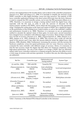
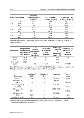
4. The proposed PSO algorithm
The main aim of the PSO algorithm is to tune the controller parameters [Kp, Kd, Ki, Ko], by
minimizing the cost function for minimum values in order to get the optimal gains value for
these parameters. The target cost function is the integral square error (ISE), this is simple
function and can easy represented in the fuzzy algorithm. The cost function (equation 4) is
calculated by swapping the searching results in the local position with the minimum value
of the function until reaching the best global search. In this case, the proposed PSO
algorithm is 6-dimension in the population size for PIDFC (also can do it by 4-dimenssion),
3-dimension in the case of the PIFC and PDFC. This dimension belongs to the controller
parameters, which represent the particle (X) inside the population space. These particles are
explained in equations (5, 6 and 7) with ith iteration path. Note that during the search
process the resulting gains were constrained by the interval [Xmin Xmax] to search with
these limits in order to cover the range of the operational range (universe of discourse). Fig.
2 shows the flow chart of the proposed PSO algorithm.
Fig. 2. Flowchart of the Proposed PSO Algorithm
www.intechopen.com](https://image.slidesharecdn.com/21950-150430172425-conversion-gate02/85/21950-5-320.jpg)
![MATLAB – A Ubiquitous Tool for the Practical Engineer202
2
0
( ( ))
Maxiteration
t
ISE e t
=
= ∑ (4)
X(PIDFC)= [x(1) x(2) x(3) x(4) x(5) x(6)]=
[Kp Kd Ko + Kp Ki Ko] , Dimension = 6
(5)
X(PIFC)= [x(1) x(2) x(3)]= [Kp Ki Ko] , Dimension = 3 (6)
X(PDFC)= [x(1) x(2) x(3)]= [Kp Kd Ko] , Dimension = 3 (7)
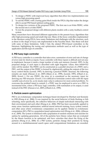
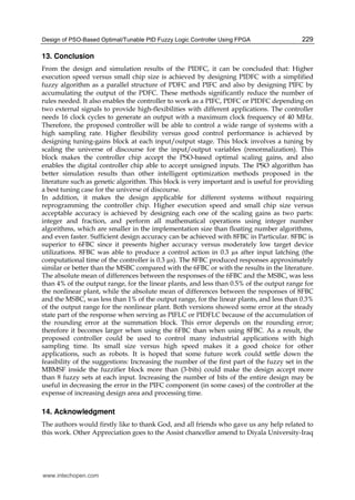
5. Block diagram of the PIDFC
The proposed controller accepts two signals, the first one is the plant output ( p
y ) and the
second one is the desired output ( d
y ), both of them are digital signals, and deliver the
control action signal as a digital output. It also accepts four 8-bit digital signals that
represent the optimal gain parameters needed by the controller ( p
K , d
K , i
K , and o
K ). These
parameters are used to aid the tuning block with optimal values of the scaling gains online
with the digital FPGA chip. Other two (one-bit) signals have been used to select the type of
the controller (PDFC, PIFC, or PIDFC) online with the chip. Fig. 3 shows the general block
diagram of the controller chip in a unity feedback control system. In recent years, many of
the digital fuzzy applications have different ranges of the accuracy. Most of them have 6-8
bits of accuracy (Poorani et al., 2005), (Tipsuwanpornet al., 2004), (Hassan et al., 2007),
(Solano et al., 1997), (Gabrielli et al., 2009), (Obaid et al., 2009), (Obaid et al., 1999). This
accuracy may affect the process behavior inside the digital fuzzy chip; also it has a trade off
with the speed of the process (Leonid , 1997), (Jantzen, 1998), (Ibrahim, 2004). Therefore, it is
necessary to find which range has better accuracy inside the digital chip. Two versions of
the proposed PIDFC were designed, the first one is an 8-bit which uses 8 bits for each
input/output variables. The second version is a 6-bit which uses 6 bits for each
input/output variable. To make the discussion clear and general for the proposed controller
in the following sections, symbol (q) will be used to represent the range of accuracy, (q=8) in
the proposed 8-bits design, and (q=6) in the 6-bits version of the proposed design.
6. Structure of the PIDFC design
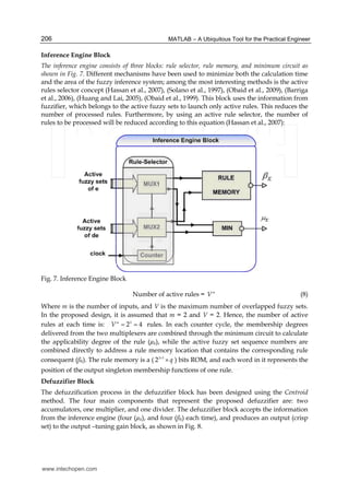
Generally, to represent PIDFC, it is required to design a fuzzy inference system with three
inputs that represent the proportional, derivative, and integral components, and each one of
them can have up to eight fuzzy sets. Therefore, the maximum number of the required fuzzy
rules is 83=512 rules. To avoid this huge number of rules, the proposed controller was
designed using two parallel PDFC to design the PIDFC as discussed earlier (Hassan et al.,
2007), (Obaid et al., 2009), (Obaid et al., 1999). The second PDFC was converted to a PIFC by
accumulating its output. Fig. 4 shows the structure of proposed PIDFC, where FIS refers to
the fuzzy inference system with its three blocks, Fuzzifier, inference engine and defuzzifier.
Both controllers, PDFC and PIFC, receive the same error signal. The structure of the single
PDFC is discussed in the next sections. The main block in the PDFC is the fuzzy inference
block which has two inputs (e(n) and ( )e nΔ ), one output (U(n)) fuzzy system of Mamdani
www.intechopen.com](https://image.slidesharecdn.com/21950-150430172425-conversion-gate02/85/21950-6-320.jpg)
![MATLAB – A Ubiquitous Tool for the Practical Engineer204
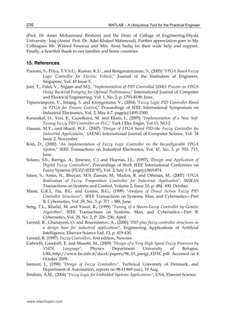
Tuning-Gain Block
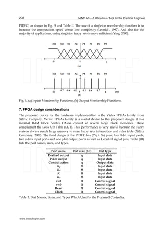
The tuning-gain block is used at each of the two inputs and also at the output of each PDFC
block. This block receives and multiplies two inputs: the variable to be scaled (input or
output) and its related gains, this implies the proposed tuning method via scaling the
universe of discourse. An eight-bit latch was used at each Tuning-gain block to store the
gain coefficient value received from one of the gain ports, depending on selection line
values. The “*” operator was used in the VHDL files of the design to express a
multiplication process just like a conventional language. This process has been designed at
the behavioral level of abstraction in VHDL code, i.e. during the design synthesis process, if
the library “IEEE.std_logic_signed” was included in the VHDL files (Hassan et al., 2007),
(Obaid et al., 2009), (Obaid et al., 1999). Fig. 5 shows the Tuning-gain block with more
details.
Fig. 5. Input/Output Tuning Block
Every “*” operator is synthesized to a signed number multiplier directly (Hassan et al., 2007),
(Obaid et al., 2009), (Obaid et al., 1999). Fig. 6 shows the Tuning-gain block with more
details. The fuzzy inference block in each PDFC can handle positive values only, and the
error and its rate signals can have positive and negative values (Hassan et al., 2007), as the
shifting process has been designed to convert the input variables range from
[ 1 1
2 2 1q q− −
− → − ] to [ 0 2 1q
→ − ]. This process implies adding the number ( 1
2q−
) to the input
variable. This addition has been designed by inverting the last bit (MSB) of the input
variable (Hassan et al., 2007), (Obaid et al., 2009), (Obaid et al., 1999). The shift process at the
www.intechopen.com](https://image.slidesharecdn.com/21950-150430172425-conversion-gate02/85/21950-8-320.jpg)
![Design of PSO-Based Optimal/Tunable PID Fuzzy Logic Controller Using FPGA 205
output has been designed using subtraction, instead of addition, to convert the range of the
output variable from [ 0 2 1q
→ − ] to [ 1 1
2 2 1q q− −
− → − ]. This specification will increase the
flexibility of the proposed design.
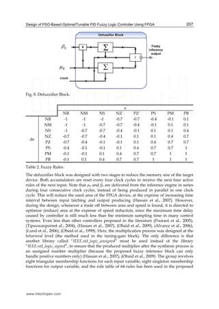
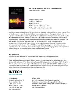
Fuzzifier Block
The overlapping degree (V) in the proposed design is two, which means that at each time
instance there are two active, (have nonzero membership values), fuzzy sets for each input
variable at maximum. The proposed fuzzification process has been designed using two
fuzzifier blocks, one for each input variable. The fuzzifier block implies the fuzzification
process by taking the input and producing four output values. These values represent the
sequence numbers of the two active fuzzy sets (e1, e2 and de1, de2) and the membership
degrees of the variable for each one of them (μe1, μe2 and μde1, μde2 ). The memory base
was designed using ROM. The use of ROM is better than RAM when the programmability is
directly achieved by the implementation techniques (as in the case of FPGA) (Barriga et al.,
2006). The fuzzifier block was designed using memory based membership functions
(MBMSF) (Solano et al., 1997), (Barriga et al., 2006). This method reduces the restrictions of
the fuzzy set shapes, even it needs a smaller memory size than other method such as the
arithmetic method. The memory model has been implemented with maximum possible
membership values in the proposed design, where the maximum coded in p values is
( 2 1p
− ), where p=4 bits in the 6-bits version of the PIDFC, and p=6 bits in the 8-bits version
of the PIDFC. This dictates that the summation of membership values of two consecutive
fuzzy set is always equal to ( 2 1p
− ). Each word in the MBMSF is divided into two parts. The
first part represents the sequence number of the active fuzzy set (3-bits, in both versions).
Assigning 3 bits for the sequence number of the fuzzy sets, gives the controller flexibility to
accept for each input variable for up-to 8 fuzzy sets. The second part of the memory word is
p bits data word which represents the membership value of the input in the active fuzzy set.
The total memory length for each input is equal to ( 2q
).
Fig. 6. Two Inputs Fuzzifier Block.
www.intechopen.com](https://image.slidesharecdn.com/21950-150430172425-conversion-gate02/85/21950-9-320.jpg)
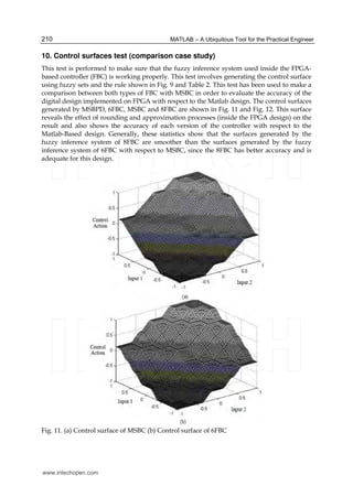
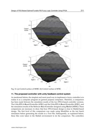
![MATLAB – A Ubiquitous Tool for the Practical Engineer212
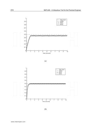
(6FBC, 8FBC, and MSBC) have been used in unity feedback control systems, and subjected
to 0.5 step input. Mathematical models of five different plants have been used for this test.
These consist of four case studies with linear systems and one case study with a nonlinear
system. Each one of these plants has been designed in MATLAB software (for simulation in
MATLAB), and also in non-synthesizable VHDL code (for simulation in ModelSim). Since
each controller could serve as PDFC, PIFC, or PIDFC, a test was made for each one of these
types. PSO was used to obtain the optimal values of the controller parameters that represent
the tuning gains. Where the information of the proposed PSO algorithm is listed as follows:
Population size: 100, W= [0.4 to 0.9], C1, C2=2, Iteration reached with every case is=1000
iteration path, and the particle searching range depends on the trial and is different in every
case. All X-axes represent the time.
11.1 First order plant (first case study)
Many industrial processes such as level process can be represented by a first order model
(Hu et al., 1999). Equation (9) shows the mathematical plant model (in s-plane). A discrete
transfer function of this model has been obtained using the ZOH method, and the selected
sampling period (T) is 0.1. Equation (10) shows the discrete transfer functions, (in z-plane).
The searching range of the particle for this case ranges from [Xmin Xmax], and by using trial
to reach the operational range with the universe of discourse. The optimal values of Kp, Kd,
Ki, and Ko used in this test were selected using PSO; and listed in Table 4.
( )1
1
1
CS s
s
=
+
(9)
( )1
0.09516
0.9048
CS z
z
=
−
, T = 0.1 (10)
Range of Particle X Controller type Gain type Value
0.0001 5X≤ ≤
PIDFC
Kp 4.5111
Kd 0.8751
Ki 4.6875
Ko 0.5625
0.0001 3.5X≤ ≤ PIFC
Kp 0.6875
Ki 2.4375
Ko 1.0212
0.0001 15X≤ ≤ PDFC
Kp 13.7501
Kd 0.6251
Ko 0.5011
Table 4. Optimal Gains Values Used With Cs1.
www.intechopen.com](https://image.slidesharecdn.com/21950-150430172425-conversion-gate02/85/21950-16-320.jpg)

![Design of PSO-Based Optimal/Tunable PID Fuzzy Logic Controller Using FPGA 215
(c)
Fig. 14. First Order Linear Plant Controlled by (a) PDFC, (b) PIFC and (c) PIDFC.
11.2 Delayed first order plant (second case study)
The time delay occurs when a sensor or an actuator is used with a physical separation (Hu
et al., 1999). Equation (11) shows the mathematical plant model (in s-plane). The discrete
transfer functions of this model were obtained using the ZOH method, and the selected
sampling period (T) is 0.1. Equation (12) shows the discrete transfer functions, (in z-plane).
The searching range of the particle for this case is [Xmin Xmax], and by using trial to reach
the operational range with the universe of discourse. The optimal values of Kp, Kd, Ki, and Ko
used in this test were selected using PSO; and listed in Table 6.
Range of Particle X Controller type Gain type Value
0.0001 1.9X≤ ≤ PIDFC
Kp 1.4372
Kd 1.687
Ki 0.5625
Ko 0.437
0.0001 1.9X≤ ≤ PIFC
Kp 0.501
Ki 1.5
Ko 0.51
0.0001 6X≤ ≤
PDFC Kp 5
Kd 0.125
Ko 0.375
Table 6. Optimal Gains Values Used With CS2.
www.intechopen.com](https://image.slidesharecdn.com/21950-150430172425-conversion-gate02/85/21950-19-320.jpg)
![MATLAB – A Ubiquitous Tool for the Practical Engineer218
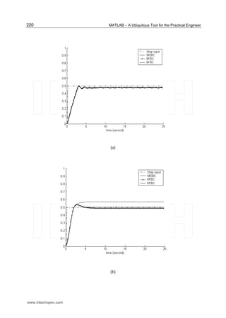
(c)
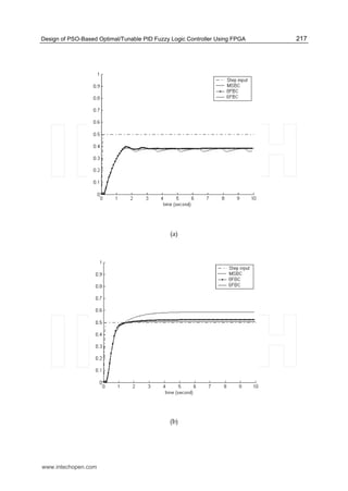
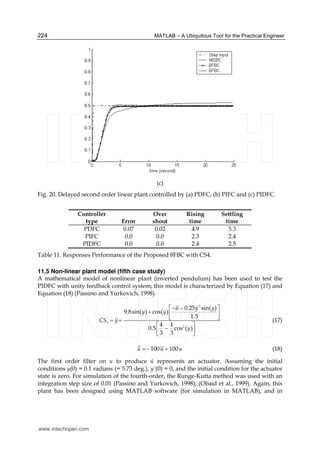
Fig. 16. Delayed first order linear plant controlled by(a) PDFC, (b) PIFC and (c) PIDFC.
11.3 Second order plant (third case study)
The position control of an AC motor process or temperature control can be represented by a
second order model (Hu et al., 1999). Equation (13) shows the mathematical plant model (in
s-plane). Discrete transfer functions of this model were obtained using the ZOH method, and
the selected sampling period (T) is 0.2. Equation (14) shows the discrete transfer functions,
(in z-plane). The searching range of the particle for this case is ranging as [Xmin Xmax], and
by using trial to reach the operational range with the universe of discourse. The optimal
values of Kp, Kd, Ki, and Ko used in this test were selected using PSO; and listed in Table 8.
( )3 2
1
4 3
CS s
s s
=
+ +
(13)
( )3 2
0.01544 z+ 0.01183
1.368 z + 0.4493
CS z
z
=
−
, T = 0.2 (14)
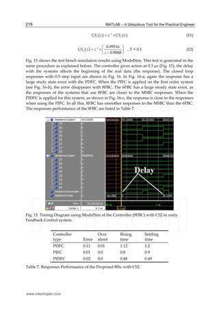
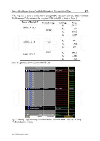
Fig. 17 shows the test bench simulation results using ModelSim for 8FBC; this test is
generated using the same procedure as explained. The controller gives action at 0.3 µs (Fig.
17). This means the same action with CS1 and CS2, which represent the linear models. The
closed loop responses with 0.5 step input are shown in Fig. 17. CS3 is a second order plant,
and has a steady state error with non-controlled response. In Fig. 18-a, when PDFC is
applied the overshoot is limited by the action of this controller, but the response still has a
steady state error. When the PIFC is applied to this system (see Fig. 18-b), the error is
disappears with 8FBC, and the system still has overshoot. The 6FBC has a rough and non-
smooth response as can be seen in the control action figures where sharp spikes appear
along the steady state part, while the responses of the systems that use 8FBC are closer to
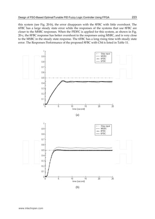
the MSBC responses. When the PIDFC is applied for this system, as shown in Fig. 18-c, the
www.intechopen.com](https://image.slidesharecdn.com/21950-150430172425-conversion-gate02/85/21950-22-320.jpg)
![Design of PSO-Based Optimal/Tunable PID Fuzzy Logic Controller Using FPGA 221
(c)
Fig. 18. Second order linear plant controlled by(a) PDFC, (b) PIFC and (c) PIDFC.
Controller
type Error
Over
shoot
Rising
time
Settling
time
PDFC 0.02 0.02 2.1 2.3
PIFC 0.005 0.03 1.89 2
PIDFC 0.0 0.005 1.6 1.8
Table 9. Responses Performance of the Proposed 8fbc with CS3.
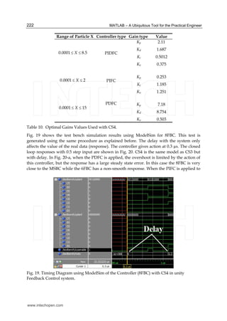
11.4 Delayed second order plant (fourth case study)
The time delay occurs when a sensor or an actuator are used with a physical separation (Hu
et al., 1999). Equation (15) shows the mathematical plant model (in s-plane). Discrete transfer
function of this model was obtained using the ZOH method, and the selected sampling
period (T) is 0.2. Equation (16) shows the discrete transfer functions, (in z-plane). The
searching range of the particle for this case is ranging as [Xmin Xmax], and by using trial to
reach the operational range with the universe of discourse. The optimal values of Kp, Kd, Ki,
and Ko used in this test were selected using PSO; and listed in Table 10.
( ) 2
4 3
CS z z CS−
= × (15)
( ) 2
4 2
0.01544 z+ 0.01183
1.368 z+ 0.4493
CS z z
z
−
⎛ ⎞
= ×⎜ ⎟
−⎝ ⎠
; T = 0.2 (16)
www.intechopen.com](https://image.slidesharecdn.com/21950-150430172425-conversion-gate02/85/21950-25-320.jpg)
![Design of PSO-Based Optimal/Tunable PID Fuzzy Logic Controller Using FPGA 225
VHDL code (for simulation in ModelSim). A special package was designed in VHDL code to
represent the trigonometric functions and fourth-order Runge-Kutta method, which are not
available in Quartus II (or in ISE) standard libraries (Obaid et al., 1999). The searching range
of the particle for this case is [Xmin Xmax], and by using trial to reach the proposed
algorithm, the values of Kp, Kd, Ki, and Ko used in this test were selected using PSO. These
values are listed in Table XII.
Range of Particle X Controller type Gain type Value
0.0001 11.5X≤ ≤ PIDFC
Kp 1.1012
Kd 10.1103
Ki 1.5013
Ko 5.0032
Table 12. Optimal Gains Values Used With CS5.
Fig. 21 shows the test bench simulation results using ModelSim for 8FBC and the controller
gives an output at 0.7 µs after the input latching (Fig. 21). The 6FBC has the same procedure
in ModelSim and produces an output at 0.62 µs. The Responses Performance of the
proposed controller with CS5 is listed in Table 13. Where the bound of the settling time of
the pendulum to reach its initial position with the force applied to the cart is -0.02 and +0.02
with both versions. The first time of the pendulum reach s the initial position is listed as the
rising time. When using a nonlinear system for testing, both versions (6FBC and 8FBC)
provide generally good responses although there is some oscillation. One must not be
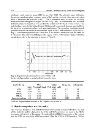
deceived by the steady state error that appears in Fig. 22, as it represents less than 1% of the
output range in the case of 6FBC and less than 0.5% of the output range, in the case of 8FBC.
The absolute mean difference between the nonlinear plant response, using MSBC, and the
Fig. 21. Timing Diagram using ModelSim of the Controller (8FBC) with CS5 in unity
Feedback Control system.
www.intechopen.com](https://image.slidesharecdn.com/21950-150430172425-conversion-gate02/85/21950-29-320.jpg)
![Design of PSO-Based Optimal/Tunable PID Fuzzy Logic Controller Using FPGA 231
Obaid, Z.A., Sulaiman, N. and Hamidon, M.N., (2009) “Developed Method of FPGA-based
Fuzzy Logic Controller Design with the Aid of Conventional PID Algorithm”, Australian
Journal of Basics and Applied Science, Vol. 3(3), P: 2724-2740.
Ying, H., (2000) "Fuzzy Control and Modeling, Analytical Foundations and Applications",
Institute of Electrical and Electronic Engineers Inc., USA.
Wang, J., Zhang, Y. and Wang, W., (2006) "Optimal design of PI/PD controller for non-minimum
phase system", Transactions of the Institute of Measurement and Control, Vol. 28 No.
1, p: 27-35.
Allaoua, B., Gasbaoui, B. and Mebarki, B., (2009) "Setting Up PID DC Motor Speed Control
Alteration Parameters Using Particle Swarm Optimization Strategy", Leonardo
Electronic Journal of Practices and Technologies, Issue 14, p: 19-32, January-June
2009.
Barriga, A., Sanchez-Solano, S., Brox, P., Cabrera, A., and Baturone, I., (2006) "Modeling and
implementation of Fuzzy Systems Based on VHDL", International Journal of
Approximate Reasoning, Elsevier Inc, Vol. 41, p: 164–178.
Huang, S.H. and Lai, J.Y., (2005) "A High Speed Fuzzy Inference Processor with Dynamic
Analysis and Scheduling Capabilities", IEICE Transaction Information & System., Vol.
E88-D, No.10 October.
Alvarez, J., Lago, A. and Nogueiras, A., (2006) "FPGA Implementation of a Fuzzy Controller for
Automobile DC-DC Converters" Proceeding of IEEE International Conference on
Field Programmable Technology, December, page(s): 237-240.
Lund, T., Aguirre, M. and Torralba, A., (2004) "Fuzzy Logic Control via an FPGA: A Design
using techniques from Digital Signal Processing", Proceedings of IEEE International
Symposium on Industrial Electronics, vol. 1, May 4-7, page(s): 555- 559.
Sultan, KH., “Inverted Pendulum, Analysis, Design and Implementation” IIEE Visionaries
Document Version 1.0, Institute of Industrial Electronics Engineering, Karachi,
Pakistan. [Available online at] Matlab Central File Exchange
http://www.Mathworks.com.
Xilinx Company. 2009. Virtex 2.5 V Field Programmable Gate Arrays, Data Sheet DS003,
URL www.xilinx.com. Accessed on 2009.
Hu, B.G., Mann, G.K. and Gosine, R.G, (1999) "New Methodology for Analytical and Optimal
Design of Fuzzy PID Controllers", IEEE Transactions on Fuzzy Systems, Vol. 7, No. 5,
pp. 521-539, October.
Passino, K.M., and Yurkovich, S., (1998) "Fuzzy Control, Addison-Weslwey Longman Inc.,
USA.
Masmoudi, N., Hachicha, M. and Kamoun, L., (1999) "Hardware Design of Programmable
Fuzzy Controller on FPGA", Proceedings of IEEE International Fuzzy Systems
Conference Proceedings, August 22-25, page(s):1675-1679.
Jain, T. and Nigam, M.J., (2008) "Optimization of PD-PI Controller Using Swarm Intelligence",
Journal of Theoretical and Applied Information Technology, Page: 1013-1018, 2008.
Obaid, Z.A., Sulaiman, N., Marhaban, M.H. and Hamidon, M.N. (2010), "Implementation of
Multistructure PID-like Fuzzy Logic Controller using Field Programmable Gate
Array” IEICE Electronics Express, Vol. 7 No. 3, P: 132-137, 10 February.
Li J. and Hu B.S., (1996) "The Architecture of Fuzzy PID Gain Conditioner and its FPGA
Prototype Implementation", Proceedings of the Second International Conference on
ASIC, October 21-24, page(s):61-65.
www.intechopen.com](https://image.slidesharecdn.com/21950-150430172425-conversion-gate02/85/21950-35-320.jpg)


![3tjedan zzv rjesenja[4]](https://cdn.slidesharecdn.com/ss_thumbnails/3tjedanzzvrjesenja4-150207060613-conversion-gate01-thumbnail.jpg?width=640&height=640&fit=bounds)


