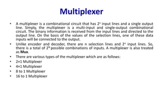
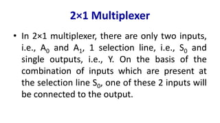
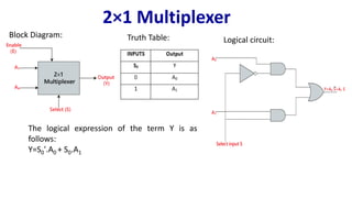
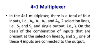
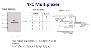
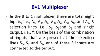
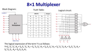
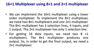
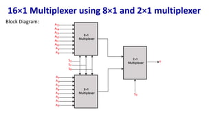
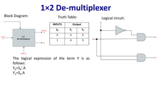
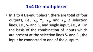
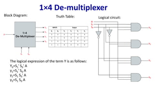
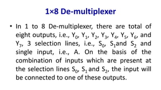
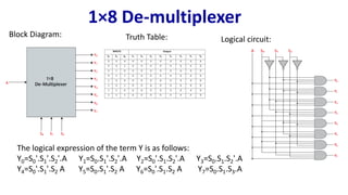
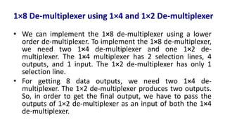
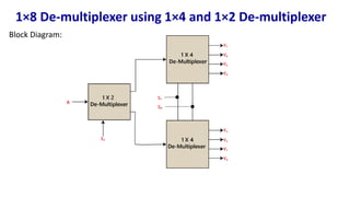
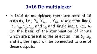
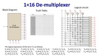
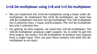
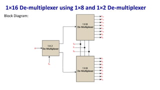
Multiplexer and Demultiplexer
Multiplexer
• A multiplexer is a combinational circuit that has 2n input lines and a single output
line. Simply, the multiplexer is a multi-input and single-output combinational
circuit. The binary information is received from the input lines and directed to the
output line. On the basis of the values of the selection lines, one of these data
inputs will be connected to the output.
• Unlike encoder and decoder, there are n selection lines and 2n input lines. So,
there is a total of 2N possible combinations of inputs. A multiplexer is also treated
as Mux.
• There are various types of the multiplexer which are as follows:
• 2×1 Multiplexer
• 4×1 Multiplexer
• 8 to 1 Multiplexer
• 16 to 1 Multiplexer
2×1 Multiplexer
• In 2×1 multiplexer, there are only two inputs,
i.e., A0 and A1, 1 selection line, i.e., S0 and
single outputs, i.e., Y. On the basis of the
combination of inputs which are present at
the selection line S0, one of these 2 inputs will
be connected to the output.
2×1 Multiplexer
Truth Table:
The logical expression of the term Y is as
follows:
Y=S0'.A0 + S0.A1
Block Diagram:
Logical circuit:
4×1 Multiplexer
• In the 4×1 multiplexer, there is a total of four
inputs, i.e., A0, A1, A2, and A3, 2 selection lines,
i.e., S0 and S1 and single output, i.e., Y. On the
basis of the combination of inputs that are
present at the selection lines S0 and S1, one of
these 4 inputs are connected to the output.
4×1 Multiplexer
Truth Table:
Block Diagram:
Logical circuit:
The logical expression of the term Y is as
follows:
Y=S1' S0' A0 + S1' S0 A1 + S1 S0' A2 + S1 S0 A3
8×1 Multiplexer
• In the 8 to 1 multiplexer, there are total eight
inputs, i.e., A0, A1, A2, A3, A4, A5, A6, and A7, 3
selection lines, i.e., S0, S1and S2 and single
output, i.e., Y. On the basis of the combination
of inputs that are present at the selection
lines S0, S1
, and S2, one of these 8 inputs are
connected to the output.
8×1 Multiplexer
Truth Table:
Block Diagram:
Logical circuit:
The logical expression of the term Y is as follows:
Y=S0'.S1'.S2'.A0 + S0.S1'.S2'.A1 + S0'.S1.S2'.A2 + S0.S1.S2'.A3 + S0'.S1'.S2 A4 + S0.S1'.S2 A5 +
S0'.S1.S2 .A6 + S0.S1.S3.A7
8×1 Multiplexer using 4×1 and 2×1 multiplexer
• We can implement the 8×1 multiplexer using a lower
order multiplexer. To implement the 8×1 multiplexer,
we need two 4×1 multiplexers and one 2×1 multiplexer.
The 4×1 multiplexer has 2 selection lines, 4 inputs, and
1 output. The 2×1 multiplexer has only 1 selection line.
• For getting 8 data inputs, we need two 4×1
multiplexers. The 4×1 multiplexer produces one
output. So, in order to get the final output, we need a
2×1 multiplexer.
8×1 Multiplexer using 4×1 and 2×1 multiplexer
Block Diagram:
16×1 Multiplexer
• In the 16 to 1 multiplexer, there are total of 16
inputs, i.e., A0, A1, …, A16, 4 selection lines, i.e.,
S0, S1, S2, and S3 and single output, i.e., Y. On
the basis of the combination of inputs that are
present at the selection lines S0, S1, and S2,
one of these 16 inputs will be connected to
the output.
16×1 Multiplexer
Truth Table:
Block Diagram:
Logical circuit:
The logical expression of the term Y is as follows:
Y=A0.S0'.S1'.S2'.S3‘ + A1.S0'.S1'.S2 '.S3 + A2.S0'.S1'.S2.S3‘ + A3.S0'.S1 '.S2.S3 + A4.S0'.S1.S2'.S3‘ + A5.S0'.S1.S2'.S3 + A6.S1.S2.S3‘ +
A7.S0'.S1.S2.S3 + A8.S0.S1'.S2'.S3‘ + A9.S0.S1'.S2'.S3 + Y10.S0.S1'.S2.S3 ‘ + A11.S0.S1'.S2.S3 + A12 S0.S1.S2 '.S3‘ + A13.S0.S1.S2'.S3 +
A14.S0.S1 .S2.S3‘ + A15.S0.S1.S2'.S3
16×1 Multiplexer using 8×1 and 2×1 multiplexer
• We can implement the 16×1 multiplexer using a lower
order multiplexer. To implement the 8×1 multiplexer,
we need two 8×1 multiplexers and one 2×1 multiplexer.
The 8×1 multiplexer has 3 selection lines, 4 inputs, and
1 output. The 2×1 multiplexer has only 1 selection line.
• For getting 16 data inputs, we need two 8 ×1
multiplexers. The 8×1 multiplexer produces one
output. So, in order to get the final output, we need a
2×1 multiplexer.
16×1 Multiplexer using 8×1 and 2×1 multiplexer
Block Diagram:
De-multiplexer
• A De-multiplexer is a combinational circuit that has only 1 input line and 2N output
lines. Simply, the multiplexer is a single-input and multi-output combinational
circuit. The information is received from the single input lines and directed to the
output line. On the basis of the values of the selection lines, the input will be
connected to one of these outputs. De-multiplexer is opposite to the multiplexer.
• Unlike encoder and decoder, there are n selection lines and 2n outputs. So, there is
a total of 2n possible combinations of inputs. De-multiplexer is also treated as De-
mux.
• There are various types of the De-multiplexer which are as follows:
• 1×2 De-multiplexer
• 1×4 De-multiplexer
• 1×8 De-multiplexer
• 1×16 De-multiplexer
1×2 De-multiplexer
• In the 1 to 2 De-multiplexer, there are only
two outputs, i.e., Y0, and Y1, 1 selection lines,
i.e., S0, and single input, i.e., A. On the basis of
the selection value, the input will be
connected to one of the outputs.
1×2 De-multiplexer
Truth Table:
The logical expression of the term Y is as
follows:
Y0=S0'.A
Y1=S0.A
Block Diagram:
Logical circuit:
1×4 De-multiplexer
• In 1 to 4 De-multiplexer, there are total of four
outputs, i.e., Y0, Y1, Y2, and Y3, 2 selection
lines, i.e., S0 and S1 and single input, i.e., A. On
the basis of the combination of inputs which
are present at the selection lines S0 and S1, the
input be connected to one of the outputs.
1×4 De-multiplexer
Truth Table:
Block Diagram:
Logical circuit:
The logical expression of the term Y is as follows:
Y0=S1' S0' A
y1=S1' S0 A
y2=S1 S0' A
y3=S1 S0 A
1×8 De-multiplexer
• In 1 to 8 De-multiplexer, there are total of
eight outputs, i.e., Y0, Y1, Y2, Y3, Y4, Y5, Y6, and
Y7, 3 selection lines, i.e., S0, S1and S2 and
single input, i.e., A. On the basis of the
combination of inputs which are present at
the selection lines S0, S1 and S2, the input will
be connected to one of these outputs.
1×8 De-multiplexer
Truth Table:
Block Diagram:
Logical circuit:
The logical expression of the term Y is as follows:
Y0=S0'.S1'.S2'.A Y1=S0.S1'.S2'.A Y2=S0'.S1.S2'.A Y3=S0.S1.S2'.A
Y4=S0'.S1'.S2 A Y5=S0.S1'.S2 A Y6=S0'.S1.S2 A Y7=S0.S1.S3.A
1×8 De-multiplexer using 1×4 and 1×2 De-multiplexer
• We can implement the 1×8 de-multiplexer using a lower
order de-multiplexer. To implement the 1×8 de-multiplexer,
we need two 1×4 de-multiplexer and one 1×2 de-
multiplexer. The 1×4 multiplexer has 2 selection lines, 4
outputs, and 1 input. The 1×2 de-multiplexer has only 1
selection line.
• For getting 8 data outputs, we need two 1×4 de-
multiplexer. The 1×2 de-multiplexer produces two outputs.
So, in order to get the final output, we have to pass the
outputs of 1×2 de-multiplexer as an input of both the 1×4
de-multiplexer.
1×8 De-multiplexer using 1×4 and 1×2 De-multiplexer
Block Diagram:
1×16 De-multiplexer
• In 1×16 de-multiplexer, there are total of 16
outputs, i.e., Y0, Y1, …, Y16, 4 selection lines,
i.e., S0, S1, S2, and S3 and single input, i.e., A.
On the basis of the combination of inputs
which are present at the selection lines S0, S1,
and S2, the input will be connected to one of
these outputs.
1×16 De-multiplexer
Truth Table:
Block Diagram:
Logical circuit:
The logical expression of the term Y is as follows:
Y0=A.S0'.S1'.S2'.S3‘ Y1=A.S0'.S1'.S2'.S3 Y2=A.S0'.S1'.S2.S3‘ Y3=A.S0'.S1'.S2.S3 Y4=A.S0'.S1.S2'.S3‘ Y5=A.S0'.S1.S2'.S3
Y6=A.S0'.S1.S2.S3‘ Y7=A.S0'.S1.S2.S3 Y8=A.S0.S1'.S2'.S3‘ Y9=A.S0.S1'.S2'.S3 Y10=A.S0.S1'.S2.S3‘ Y11=A.S0.S1'.S2.S3
Y12=A.S0.S1.S2'.S3‘ Y13=A.S0.S1.S2'.S3 Y14=A.S0.S1.S2.S3‘ Y15=A.S0.S1.S2'.S3
1×16 De-multiplexer using 1×8 and 1×2 De-multiplexer
• We can implement the 1×16 de-multiplexer using a lower order de-
multiplexer. To implement the 1×16 de-multiplexer, we need two
1×8 de-multiplexer and one 1×2 de-multiplexer. The 1×8 multiplexer
has 3 selection lines, 1 input, and 8 outputs. The 1×2 de-multiplexer
has only 1 selection line.
• For getting 16 data outputs, we need two 1×8 de-multiplexer. The
1×8 de-multiplexer produces eight outputs. So, in order to get the
final output, we need a 1×2 de-multiplexer to produce two outputs
from a single input. Then we pass these outputs into both the de-
multiplexer as an input.
1×16 De-multiplexer using 1×8 and 1×2 De-multiplexer
Block Diagram:
Multiplexer and demultiplexer for digital logic circuitpdf

Multiplexer and demultiplexer for digital logic circuitpdf

  • 1.
  • 2.
    Multiplexer • A multiplexeris a combinational circuit that has 2n input lines and a single output line. Simply, the multiplexer is a multi-input and single-output combinational circuit. The binary information is received from the input lines and directed to the output line. On the basis of the values of the selection lines, one of these data inputs will be connected to the output. • Unlike encoder and decoder, there are n selection lines and 2n input lines. So, there is a total of 2N possible combinations of inputs. A multiplexer is also treated as Mux. • There are various types of the multiplexer which are as follows: • 2×1 Multiplexer • 4×1 Multiplexer • 8 to 1 Multiplexer • 16 to 1 Multiplexer
  • 3.
    2×1 Multiplexer • In2×1 multiplexer, there are only two inputs, i.e., A0 and A1, 1 selection line, i.e., S0 and single outputs, i.e., Y. On the basis of the combination of inputs which are present at the selection line S0, one of these 2 inputs will be connected to the output.
  • 4.
    2×1 Multiplexer Truth Table: Thelogical expression of the term Y is as follows: Y=S0'.A0 + S0.A1 Block Diagram: Logical circuit:
  • 5.
    4×1 Multiplexer • Inthe 4×1 multiplexer, there is a total of four inputs, i.e., A0, A1, A2, and A3, 2 selection lines, i.e., S0 and S1 and single output, i.e., Y. On the basis of the combination of inputs that are present at the selection lines S0 and S1, one of these 4 inputs are connected to the output.
  • 6.
    4×1 Multiplexer Truth Table: BlockDiagram: Logical circuit: The logical expression of the term Y is as follows: Y=S1' S0' A0 + S1' S0 A1 + S1 S0' A2 + S1 S0 A3
  • 7.
    8×1 Multiplexer • Inthe 8 to 1 multiplexer, there are total eight inputs, i.e., A0, A1, A2, A3, A4, A5, A6, and A7, 3 selection lines, i.e., S0, S1and S2 and single output, i.e., Y. On the basis of the combination of inputs that are present at the selection lines S0, S1 , and S2, one of these 8 inputs are connected to the output.
  • 8.
    8×1 Multiplexer Truth Table: BlockDiagram: Logical circuit: The logical expression of the term Y is as follows: Y=S0'.S1'.S2'.A0 + S0.S1'.S2'.A1 + S0'.S1.S2'.A2 + S0.S1.S2'.A3 + S0'.S1'.S2 A4 + S0.S1'.S2 A5 + S0'.S1.S2 .A6 + S0.S1.S3.A7
  • 9.
    8×1 Multiplexer using4×1 and 2×1 multiplexer • We can implement the 8×1 multiplexer using a lower order multiplexer. To implement the 8×1 multiplexer, we need two 4×1 multiplexers and one 2×1 multiplexer. The 4×1 multiplexer has 2 selection lines, 4 inputs, and 1 output. The 2×1 multiplexer has only 1 selection line. • For getting 8 data inputs, we need two 4×1 multiplexers. The 4×1 multiplexer produces one output. So, in order to get the final output, we need a 2×1 multiplexer.
  • 10.
    8×1 Multiplexer using4×1 and 2×1 multiplexer Block Diagram:
  • 11.
    16×1 Multiplexer • Inthe 16 to 1 multiplexer, there are total of 16 inputs, i.e., A0, A1, …, A16, 4 selection lines, i.e., S0, S1, S2, and S3 and single output, i.e., Y. On the basis of the combination of inputs that are present at the selection lines S0, S1, and S2, one of these 16 inputs will be connected to the output.
  • 12.
    16×1 Multiplexer Truth Table: BlockDiagram: Logical circuit: The logical expression of the term Y is as follows: Y=A0.S0'.S1'.S2'.S3‘ + A1.S0'.S1'.S2 '.S3 + A2.S0'.S1'.S2.S3‘ + A3.S0'.S1 '.S2.S3 + A4.S0'.S1.S2'.S3‘ + A5.S0'.S1.S2'.S3 + A6.S1.S2.S3‘ + A7.S0'.S1.S2.S3 + A8.S0.S1'.S2'.S3‘ + A9.S0.S1'.S2'.S3 + Y10.S0.S1'.S2.S3 ‘ + A11.S0.S1'.S2.S3 + A12 S0.S1.S2 '.S3‘ + A13.S0.S1.S2'.S3 + A14.S0.S1 .S2.S3‘ + A15.S0.S1.S2'.S3
  • 13.
    16×1 Multiplexer using8×1 and 2×1 multiplexer • We can implement the 16×1 multiplexer using a lower order multiplexer. To implement the 8×1 multiplexer, we need two 8×1 multiplexers and one 2×1 multiplexer. The 8×1 multiplexer has 3 selection lines, 4 inputs, and 1 output. The 2×1 multiplexer has only 1 selection line. • For getting 16 data inputs, we need two 8 ×1 multiplexers. The 8×1 multiplexer produces one output. So, in order to get the final output, we need a 2×1 multiplexer.
  • 14.
    16×1 Multiplexer using8×1 and 2×1 multiplexer Block Diagram:
  • 15.
    De-multiplexer • A De-multiplexeris a combinational circuit that has only 1 input line and 2N output lines. Simply, the multiplexer is a single-input and multi-output combinational circuit. The information is received from the single input lines and directed to the output line. On the basis of the values of the selection lines, the input will be connected to one of these outputs. De-multiplexer is opposite to the multiplexer. • Unlike encoder and decoder, there are n selection lines and 2n outputs. So, there is a total of 2n possible combinations of inputs. De-multiplexer is also treated as De- mux. • There are various types of the De-multiplexer which are as follows: • 1×2 De-multiplexer • 1×4 De-multiplexer • 1×8 De-multiplexer • 1×16 De-multiplexer
  • 16.
    1×2 De-multiplexer • Inthe 1 to 2 De-multiplexer, there are only two outputs, i.e., Y0, and Y1, 1 selection lines, i.e., S0, and single input, i.e., A. On the basis of the selection value, the input will be connected to one of the outputs.
  • 17.
    1×2 De-multiplexer Truth Table: Thelogical expression of the term Y is as follows: Y0=S0'.A Y1=S0.A Block Diagram: Logical circuit:
  • 18.
    1×4 De-multiplexer • In1 to 4 De-multiplexer, there are total of four outputs, i.e., Y0, Y1, Y2, and Y3, 2 selection lines, i.e., S0 and S1 and single input, i.e., A. On the basis of the combination of inputs which are present at the selection lines S0 and S1, the input be connected to one of the outputs.
  • 19.
    1×4 De-multiplexer Truth Table: BlockDiagram: Logical circuit: The logical expression of the term Y is as follows: Y0=S1' S0' A y1=S1' S0 A y2=S1 S0' A y3=S1 S0 A
  • 20.
    1×8 De-multiplexer • In1 to 8 De-multiplexer, there are total of eight outputs, i.e., Y0, Y1, Y2, Y3, Y4, Y5, Y6, and Y7, 3 selection lines, i.e., S0, S1and S2 and single input, i.e., A. On the basis of the combination of inputs which are present at the selection lines S0, S1 and S2, the input will be connected to one of these outputs.
  • 21.
    1×8 De-multiplexer Truth Table: BlockDiagram: Logical circuit: The logical expression of the term Y is as follows: Y0=S0'.S1'.S2'.A Y1=S0.S1'.S2'.A Y2=S0'.S1.S2'.A Y3=S0.S1.S2'.A Y4=S0'.S1'.S2 A Y5=S0.S1'.S2 A Y6=S0'.S1.S2 A Y7=S0.S1.S3.A
  • 22.
    1×8 De-multiplexer using1×4 and 1×2 De-multiplexer • We can implement the 1×8 de-multiplexer using a lower order de-multiplexer. To implement the 1×8 de-multiplexer, we need two 1×4 de-multiplexer and one 1×2 de- multiplexer. The 1×4 multiplexer has 2 selection lines, 4 outputs, and 1 input. The 1×2 de-multiplexer has only 1 selection line. • For getting 8 data outputs, we need two 1×4 de- multiplexer. The 1×2 de-multiplexer produces two outputs. So, in order to get the final output, we have to pass the outputs of 1×2 de-multiplexer as an input of both the 1×4 de-multiplexer.
  • 23.
    1×8 De-multiplexer using1×4 and 1×2 De-multiplexer Block Diagram:
  • 24.
    1×16 De-multiplexer • In1×16 de-multiplexer, there are total of 16 outputs, i.e., Y0, Y1, …, Y16, 4 selection lines, i.e., S0, S1, S2, and S3 and single input, i.e., A. On the basis of the combination of inputs which are present at the selection lines S0, S1, and S2, the input will be connected to one of these outputs.
  • 25.
    1×16 De-multiplexer Truth Table: BlockDiagram: Logical circuit: The logical expression of the term Y is as follows: Y0=A.S0'.S1'.S2'.S3‘ Y1=A.S0'.S1'.S2'.S3 Y2=A.S0'.S1'.S2.S3‘ Y3=A.S0'.S1'.S2.S3 Y4=A.S0'.S1.S2'.S3‘ Y5=A.S0'.S1.S2'.S3 Y6=A.S0'.S1.S2.S3‘ Y7=A.S0'.S1.S2.S3 Y8=A.S0.S1'.S2'.S3‘ Y9=A.S0.S1'.S2'.S3 Y10=A.S0.S1'.S2.S3‘ Y11=A.S0.S1'.S2.S3 Y12=A.S0.S1.S2'.S3‘ Y13=A.S0.S1.S2'.S3 Y14=A.S0.S1.S2.S3‘ Y15=A.S0.S1.S2'.S3
  • 26.
    1×16 De-multiplexer using1×8 and 1×2 De-multiplexer • We can implement the 1×16 de-multiplexer using a lower order de- multiplexer. To implement the 1×16 de-multiplexer, we need two 1×8 de-multiplexer and one 1×2 de-multiplexer. The 1×8 multiplexer has 3 selection lines, 1 input, and 8 outputs. The 1×2 de-multiplexer has only 1 selection line. • For getting 16 data outputs, we need two 1×8 de-multiplexer. The 1×8 de-multiplexer produces eight outputs. So, in order to get the final output, we need a 1×2 de-multiplexer to produce two outputs from a single input. Then we pass these outputs into both the de- multiplexer as an input.
  • 27.
    1×16 De-multiplexer using1×8 and 1×2 De-multiplexer Block Diagram: