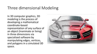
Three dimensional Modeling
In3D computer graphics, 3D
modeling is the process of
developing a mathematical
coordinate-based
representation of any surface of
an object (inanimate or living)
in three dimensions via
specialized software by
manipulating edges, vertices,
and polygons in a simulated 3D
space.
3.
3D modeling
• 3Dmodels are easier to interpret.
• Simulation under real-life conditions.
• Less expensive than building a physical model.
• 3D models can be used to perform finite element analysis (stress,
deflection, thermal…..).
• 3D models can be used directly in manufacturing, Computer
Numerical Control (CNC).
• 3D models can be used for presentations and marketing.
4.
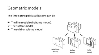
Geometric models
The threeprincipal classifications can be
Ø The line model (wireframe model)
Ø The surface model
Ø The solid or volume model
5.
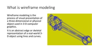
What is wireframemodeling
Wireframe modeling is the
process of visual presentation of
a three-dimensional or physical
object used in 3-D computer
graphics.
It is an abstract edge or skeletal
representation of a real-world 3-
D object using lines and curves.
6.
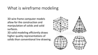
What is wireframemodeling
3D wire frame computer models
allow for the construction and
manipulation of solids and solid
surfaces.
3D solid modeling efficiently draws
higher quality representations of
solids than conventional line drawing.
7.
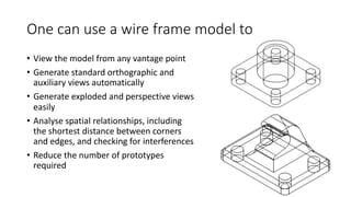
One can usea wire frame model to
• View the model from any vantage point
• Generate standard orthographic and
auxiliary views automatically
• Generate exploded and perspective views
easily
• Analyse spatial relationships, including
the shortest distance between corners
and edges, and checking for interferences
• Reduce the number of prototypes
required
8.
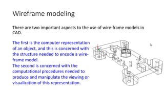
Wireframe modeling
There aretwo important aspects to the use of wire-frame models in
CAD.
The first is the computer representation
of an object, and this is concerned with
the structure needed to encode a wire-
frame model.
The second is concerned with the
computational procedures needed to
produce and manipulate the viewing or
visualization of this representation.
9.
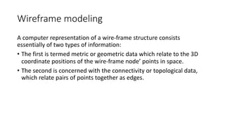
Wireframe modeling
A computerrepresentation of a wire-frame structure consists
essentially of two types of information:
• The first is termed metric or geometric data which relate to the 3D
coordinate positions of the wire-frame node’ points in space.
• The second is concerned with the connectivity or topological data,
which relate pairs of points together as edges.
10.
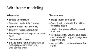
Wireframe modeling
Advantages
• Simpleto construct
• Designer needs little training
• System needs little memory
• Take less manipulation time
• Retrieving and editing can be done
easy
• Consumes less time
• Best suitable for manipulations as
orthographic isometric and
perspective views.
Disadvantages
• Image causes confusion
• Cannot get required information
from this model
• Hidden line removal features not
available
• Not possible for volume and mass
calculation, NC programming cross
sectioning etc
• Not suitable to represent complex
solids
11.
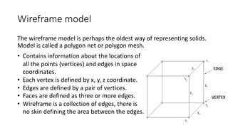
Wireframe model
The wireframemodel is perhaps the oldest way of representing solids.
Model is called a polygon net or polygon mesh.
• Contains information about the locations of
all the points (vertices) and edges in space
coordinates.
• Each vertex is defined by x, y, z coordinate.
• Edges are defined by a pair of vertices.
• Faces are defined as three or more edges.
• Wireframe is a collection of edges, there is
no skin defining the area between the edges.
12.
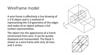
Wireframe model
A wireframe is effectively a line drawing of
a 3-D object and is a method of
representing the 3-D geometry of the edges
and nodes of an object without a full
surface representation.
The object has the appearance of a frame
constructed from wire. It can be quickly
displayed and manipulated. The block is
shown as a wire frame with only 16 lines
and 2 circles.
13.
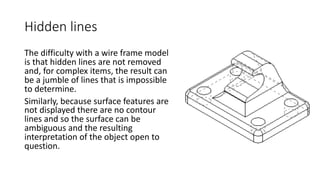
Hidden lines
The difficultywith a wire frame model
is that hidden lines are not removed
and, for complex items, the result can
be a jumble of lines that is impossible
to determine.
Similarly, because surface features are
not displayed there are no contour
lines and so the surface can be
ambiguous and the resulting
interpretation of the object open to
question.
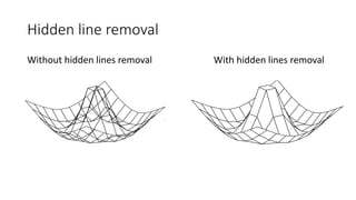
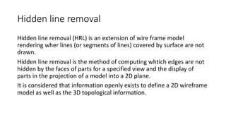
Hidden line removal
Hiddenline removal (HRL) is an extension of wire frame model
rendering wher lines (or segments of lines) covered by surface are not
drawn.
Hidden line removal is the method of computing whtich edges are not
hidden by the faces of parts for a specified view and the display of
parts in the projection of a model into a 2D plane.
It is considered that information openly exists to define a 2D wireframe
model as well as the 3D topological information.
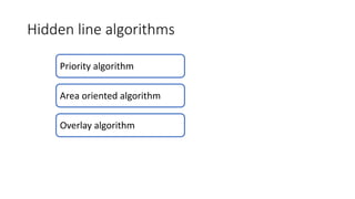
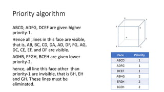
Priority algorithm
ABCD, ADFG,DCEF are given higher
priority-1.
Hence all ,lines in this face are visible,
that is, AB, BC, CD, DA, AD, DF, FG, AG,
DC, CE, EF, and DF are visible.
AGHB, EFGH, BCEH are given lower
priority-2.
hence, all line this face other than
priority-1 are invisible, that is BH, EH
and GH. These lines must be
eliminated.
Face Priority
ABCD 1
ADFG 1
DCEF 1
ABHG 2
EFGH 2
BCEH 2
18.
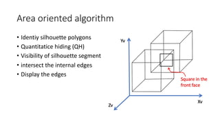
Area oriented algorithm
•Identiy silhouette polygons
• Quantitatice hiding (QH)
• Visibility of silhouette segment
• intersect the internal edges
• Display the edges
19.
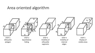
Area oriented algorithm
STEP1
Silhouette
polygon
STEP 2
Quantitative
hiding
STEP 3
Visibility of
silhouette
segments
STEP 4
Visibility of
internal
edges
STEP 5
Display of
visible areas
20.
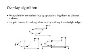
Overlay algorithm
• Acceptablefor curved surface by approximating them as plannar
surfaces.
• U-v grid is used to make grid surface by making it as straight edges.
21.
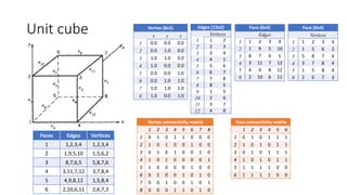
Basic database structures
•Relational database
– A set of lists, uses arrays for
storage
• Hierarchical database
– A trees structure, think of a
company’s executive structure
• Network database
– Use data pointers
Vertex list Edge list
V1(0,0,0) E1[V1,V2]
V2(1,0,0) E2[V2,V3]
V3(0,1,0) E3[V3,V1]
V4(0,0,1) E4[V2,V4]
E5[V4,V3]
E6[V1,V4]
22.
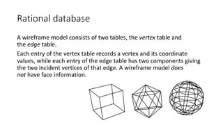
Rational database
A wireframemodel consists of two tables, the vertex table and
the edge table.
Each entry of the vertex table records a vertex and its coordinate
values, while each entry of the edge table has two components giving
the two incident vertices of that edge. A wireframe model does
not have face information.
23.
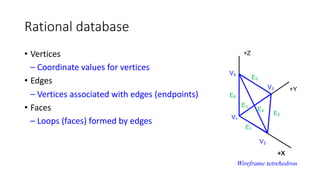
Rational database
• Vertices
–Coordinate values for vertices
• Edges
– Vertices associated with edges (endpoints)
• Faces
– Loops (faces) formed by edges
+X
+Y
+Z
+X
V2
V1
V3
V4
E2
E5
E1
E4
E3
E6
Wireframe tetrehedron
24.
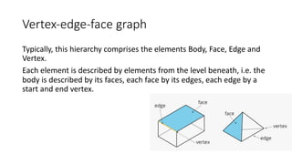
Vertex-edge-face graph
Typically, thishierarchy comprises the elements Body, Face, Edge and
Vertex.
Each element is described by elements from the level beneath, i.e. the
body is described by its faces, each face by its edges, each edge by a
start and end vertex.
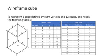
Wireframe cube
To representa cube defined by eight vertices and 12 edges, one needs
the following tables :
Vertex Table
Vertex # x y z
1 1 1 1
2 1 -1 1
3 -1 -1 1
4 -1 1 1
5 1 1 -1
6 1 -1 -1
7 -1 -1 -1
8 -1 1 -1
Edge Table
Edge # Start Vertex End Vertex
1 1 2
2 2 3
3 3 4
4 4 1
5 5 6
6 6 7
7 7 8
8 8 5
9 1 5
10 2 6
11 3 7
12 4 8
27.
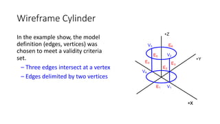
Wireframe Cylinder
In theexample show, the model
definition (edges, vertices) was
chosen to meet a validity criteria
set.
– Three edges intersect at a vertex
– Edges delimited by two vertices
+Y
+X
+Z
+X
V1
V4
V2
V3
E2
E6
E1
E3
E4
E1
E5
28.
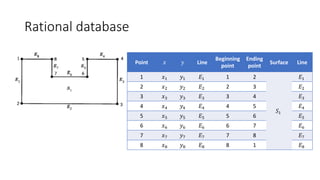
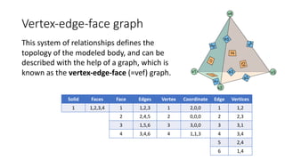
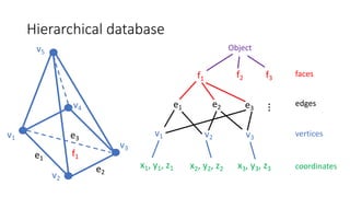
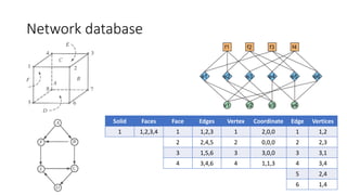
Vertex-edge-face graph
This systemof relationships defines the
topology of the modeled body, and can be
described with the help of a graph, which is
known as the vertex-edge-face (=vef) graph.
Solid Faces Face Edges Vertex Coordinate Edge Vertices
1 1,2,3,4 1 1,2,3 1 2,0,0 1 1,2
2 2,4,5 2 0,0,0 2 2,3
3 1,5,6 3 3,0,0 3 3,1
4 3,4,6 4 1,1,3 4 3,4
5 2,4
6 1,4
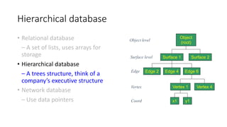
Hierarchical database
• Relationaldatabase
– A set of lists, uses arrays for
storage
• Hierarchical database
– A trees structure, think of a
company’s executive structure
• Network database
– Use data pointers
Object
(root)
Surface 2
Surface 1
Edge 2
Vertex 1
Edge 4 Edge 6
Vertex 4
x1 y1
Edge
Surface level
Object level
Vertex
Coord
31.
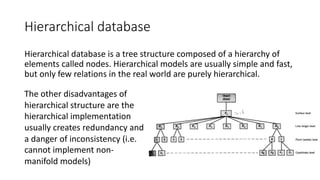
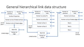
Hierarchical database
Hierarchical databaseis a tree structure composed of a hierarchy of
elements called nodes. Hierarchical models are usually simple and fast,
but only few relations in the real world are purely hierarchical.
The other disadvantages of
hierarchical structure are the
hierarchical implementation
usually creates redundancy and
a danger of inconsistency (i.e.
cannot implement non-
manifold models)
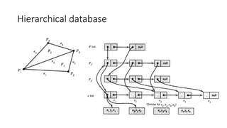
General hierarchical linkdata structure
Surface Properties
Pointer to
previous
Pointer to
next
Pointer to list of linked-vertices
Pointer to list of linked-edges
Next link
Pointer to
edge
Pointer to vertex P1
Pointer to
previous
Pointer to
next
Pointer to vertex P2
Pointer to face 1
Next link
Pointer to
vertex
Pointer to list faces
Pointer to
previous
Pointer to
next
Pointer to list of linked-edges
Real x
List of
faces
Linked-edges
Pointer to face 2
Linked-vertex
List of
edges
Real y
Real z
List of
vertices
35.
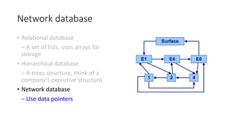
Network database
• Relationaldatabase
– A set of lists, uses arrays for
storage
• Hierarchical database
– A trees structure, think of a
company’s executive structure
• Network database
– Use data pointers
Surface
E4
E1 E6
1 2 4
36.
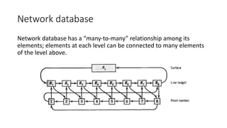
Network database
Network databasehas a “many-to-many” relationship among its
elements; elements at each level can be connected to many elements
of the level above.
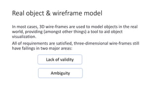
Real object &wireframe model
In most cases, 3D wire-frames are used to model objects in the real
world, providing (amongst other things) a tool to aid object
visualization.
All of requirements are satisfied, three-dimensional wire-frames still
have failings in two major areas:
Lack of validity
Ambiguity
39.
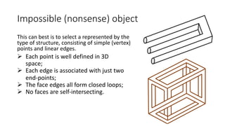
Impossible (nonsense) object
Thiscan best is to select a represented by the
type of structure, consisting of simple (vertex)
points and linear edges.
Ø Each point is well defined in 3D
space;
Ø Each edge is associated with just two
end-points;
Ø The face edges all form closed loops;
Ø No faces are self-intersecting.
40.
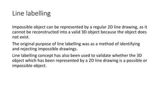
Line labelling
Impossible objectcan be represented by a regular 2D line drawing, as it
cannot be reconstructed into a valid 3D object because the object does
not exist.
The original purpose of line labelling was as a method of identifying
and rejecting impossible drawings.
Line labelling concept has also been used to validate whether the 3D
object which has been represented by a 2D line drawing is a possible or
impossible object.
41.
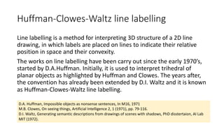
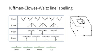
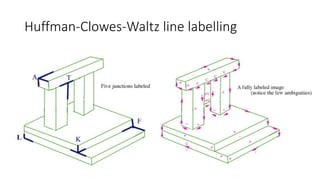
Huffman-Clowes-Waltz line labelling
Linelabelling is a method for interpreting 3D structure of a 2D line
drawing, in which labels are placed on lines to indicate their relative
position in space and their convexity.
The works on line labelling have been carry out since the early 1970’s,
started by D.A.Huffman. Initially, it is used to interpret trihedral of
planar objects as highlighted by Huffman and Clowes. The years after,
the convention has already been extended by D.I. Waltz and it is known
as Huffman-Clowes-Waltz line labelling.
D.A. Huffman, Impossible objects as nonsense sentences, In M16, 1971
M.B. Clowes, On seeing things, Artificial Intelligence 2, 1 (1971), pp. 79-116.
D.I. Waltz, Generating semantic descriptions from drawings of scenes with shadows, PhD disstertaion, AI Lab
MIT (1972).
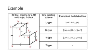
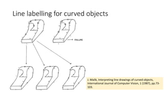
Line labelling forcurved objects
J. Malik, Interpreting line drawings of curved objects,
International Journal of Computer Vision, 1 (1987), pp.73-
103.
46.
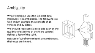
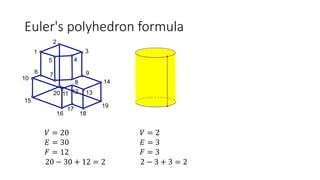
Ambiguity
While wireframe usesthe simplest data
structures, it is ambiguous. The following is a
well-known example that consists of 16
vertices and 32 edges.
We know it represents a solid and each of the
quadrilaterals (some of them are squares)
defines a face of the solid.
Because of wireframe models are ambiguous,
their uses are limited.
47.
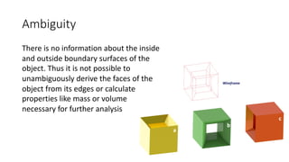
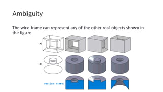
Ambiguity
There is noinformation about the inside
and outside boundary surfaces of the
object. Thus it is not possible to
unambiguously derive the faces of the
object from its edges or calculate
properties like mass or volume
necessary for further analysis
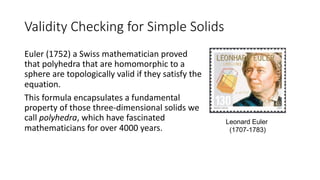
Validity Checking forSimple Solids
Euler (1752) a Swiss mathematician proved
that polyhedra that are homomorphic to a
sphere are topologically valid if they satisfy the
equation.
This formula encapsulates a fundamental
property of those three-dimensional solids we
call polyhedra, which have fascinated
mathematicians for over 4000 years.
Leonard Euler
(1707-1783)
50.
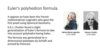
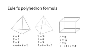
Euler's polyhedron formula
Itappears to have been the French
mathematician Legendre who gave the
first proof using Spherical Geometry.
S.A.J. L’huilier found a slight
generalization of Euler's formula to take
into account polyhedra having holes.
The formula was generalized to n-
dimensional polytopes by Schlafli and
proved by Poincare.
Adrian Marie Legendre
(1752-1833)
Simone L’huilier
(1750-1840)
51.
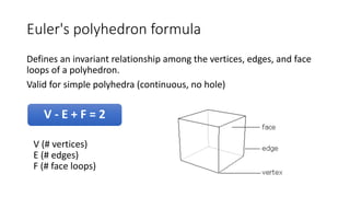
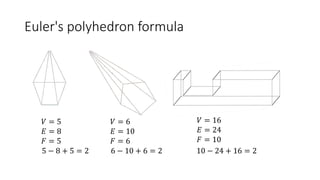
Euler's polyhedron formula
Definesan invariant relationship among the vertices, edges, and face
loops of a polyhedron.
Valid for simple polyhedra (continuous, no hole)
V - E + F = 2
V (# vertices)
E (# edges)
F (# face loops)
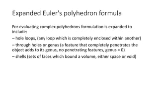
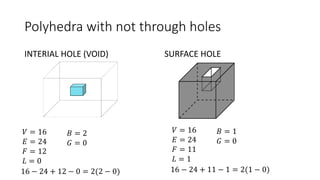
Expanded Euler's polyhedronformula
For evaluating complex polyhedrons formulation is expanded to
include:
– hole loops, (any loop which is completely enclosed within another)
– through holes or genus (a feature that completely penetrates the
object adds to its genus, no penetrating features, genus = 0)
– shells (sets of faces which bound a volume, either space or void)
57.
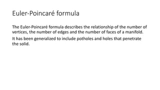
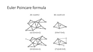
Euler-Poincaré formula
The Euler-Poincaréformula describes the relationship of the number of
vertices, the number of edges and the number of faces of a manifold.
It has been generalized to include potholes and holes that penetrate
the solid.
58.
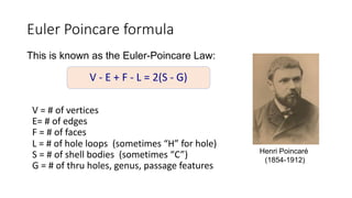
Euler Poincare formula
Thisis known as the Euler-Poincare Law:
Henri Poincaré
(1854-1912)
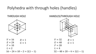
V - E + F - L = 2(S - G)
V = # of vertices
E= # of edges
F = # of faces
L = # of hole loops (sometimes “H” for hole)
S = # of shell bodies (sometimes “C”)
G = # of thru holes, genus, passage features
59.
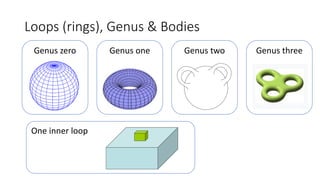
Loops (rings), Genus& Bodies
Genus zero Genus one Genus two
One inner loop
Genus three
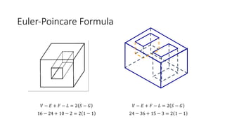
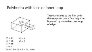
Polyhedra with faceof inner loop
𝑉 = 24
𝐸 = 36
𝐹 = 16
𝐿 = 2
24 − 36 + 16 − 2 = 2(1 − 0)
𝐵 = 1
𝐺 = 0
These are same to the first with
the exception that a face might be
bounded by more than one loop
of edges.

![Basic database structures
• Relational database
– A set of lists, uses arrays for
storage
• Hierarchical database
– A trees structure, think of a
company’s executive structure
• Network database
– Use data pointers
Vertex list Edge list
V1(0,0,0) E1[V1,V2]
V2(1,0,0) E2[V2,V3]
V3(0,1,0) E3[V3,V1]
V4(0,0,1) E4[V2,V4]
E5[V4,V3]
E6[V1,V4]](https://image.slidesharecdn.com/lecture-6-wireframe-modeling-250423143326-d39836b6/85/lecture-6-wireframe-modeling-pdf_types-of-it-21-320.jpg)