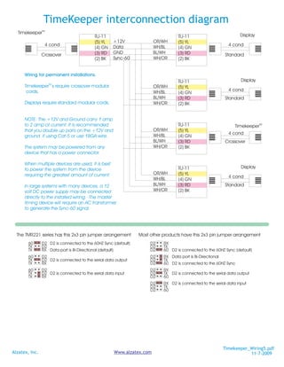
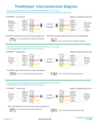
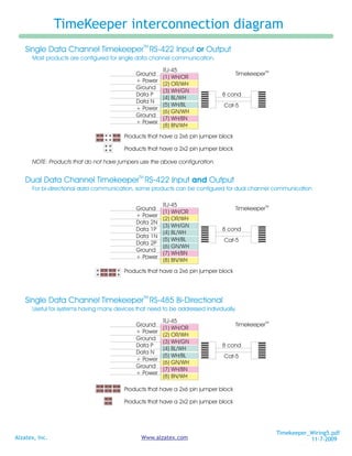
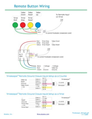
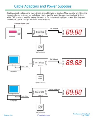
TimeKeeper interconnection diagram
                                                                                            This document describes typical connector arrangements for some
                                                               RYG Indicator
                                                                                            Alzatex products. It also includes the detailed wiring connections
                 Start                                                                      for serial connections and remote ground closure inputs used on
                 Stop
    TimeKeeper                                                                              Alzatex products.
                          TX                    RX

 Use Standard Phone Cord when                                                               TimekeeperTM                                                                             TimekeeperTM
 connecting the TimeKeeper to a RYG display
                                                                                            TMR-221 Connectors                                                                       DA-216 Connectors
                                                              Remote Display

                 Start
                 Stop                                                                       Alzatex, Inc.                                                                                     RSSR
    TimeKeeper                                                                                www.alzatex.com                                                                                             TX-422 RX-422                    Power In


                                                                                                                                                                                              D3
                                                                                                                                                                                              D1
                                                                                                                                                                                              D2
                          TX                    RX                                                                                                              Antenna


                                                                                                                                                                                                                                          12-24 VDC
                                                                                            TMR-221D/SM8


                                                                                                                                                                                                                                          9-20 VAC
                                                                                                                                                                                         RX
 Use Standard Phone Cord when


                                                                                                                                                                                              +V
                                                                                                                                                                                              GND
                                                                                                                                                                                              D4
                                                                                            D3-Tmr Start

 connecting the TimeKeeper to a remote display
                                                                                                V+ Power                                     Rem
                                                                                            D1-Stop,Down
                                                                                                                                                                                         TX                                     +
                                                              Relay Module                        Ground
                                                                                                D2-Reset
                 Start                                                                       D4-Tallye Up                                                                                Alzatex, Inc.
    TimeKeeper
                 Stop

                          TX
                                                                                                D3-TX                                                     RX                             www.alzatex.com
                                                RX                                                   V+
                                                                                               D1-RX
                                                                                                                                                                           DA-216A0 Keypad
 Use Standard Phone Cord when                                                                  Ground
                                                                                                                                                                   Contains FCC ID: OUR-XBEE/OUR-XBEEPRO* The
 connecting the TimeKeeper to a relay module                                                  D2-Sync
                                                                                                                                                                   enclosed device complies with Part 15 of the FCC Rules.
                                                                                                      D3-RX                                               TX       Operation is subject to the following two conditions: (i.) this
                                                                                                         V+
                                                                                                                                                                   device may not cause harmful interference and (ii.) this
                 Start                                                   Start                      D1-TX
                 Stop                                                    Stop
                                                                                                   Ground
                                                                                                                                                                   device must accept any inter-ference received, including
    TimeKeeper            TX                    RX      TimeKeeper                                                                                                 interference that may cause undesired operation.
                                                                                                  D2-Sync

  Use Crossover Phone Cord when
  connecting two TimeKeepers together.                                                                                                                          You will notice that some products have RS-422 jacks,
                                                                                             AC 9-18 volts
                                                      Distribution Box                                                                                          some have RJ-11/14 jacks and some have both.
                                                                                             DC 11-20 volts
                 Start
                                                                                                                                                                Alzatex manufactures adapters to convert from one
                 Stop
                          TX                                                                                                                                    type to another.
    TimeKeeper                                  RX
                                                                                                  RYG-11 and RYG-400 Connectors
 Use Crossover Phone Cord when
                                                                                                                                        Model RYG-400B0


 connecting the TimeKeeper to a distribution box..
                                                                                                                                                                Power In


                                                                                                                                                                                                     +
                                                                                                      Alzatex, Inc.
                                                                                                                      www.alzatex.com


 Typical connection arrangements
 (above).
                                                                                                                                                                           9-20 VAC or


                                                                                                                                                                                          RX-232     RX-422
                                                                                                                                                                           12-24 VDC


 Connectors for various controllers
 and displays (side, below)

  DSP254 Display Connectors                                                      DSP-504 display Connectors                                                                                    DSP-254, DSP-256 display Connectors

            Alzatex, Inc.                                                        Alzatex, Inc.                                                                                                             Alzatex, Inc.
              www.alzatex.com                                                    www.alzatex.com                                                                                                           www.alzatex.com
   Model DSP454-RYG                                                              Model DSP-500F0                                                                                                 Model DSP-254/6E0
    RSSR    TX      RX                               J3-RSSR                      RSSR    TX     RX                                                             J3-RSSR
                                                     D3 - Count Up                                                                                              D3 - Count Up                                     J1      RX-422 TX-422
   J3            J5               J2                 D1 - Reset                  J3          J5                                          J2                     D1 - Reset
                                                     D2 - Stop/Down                                                                                                                              TEST
                                                                                   GND


                                                                                                      GND


                                                                                                                                                          GND


                                                                                                                                                                D2 - Stop/Down
        GND


                            GND


                                             GND


                                                                                   +V


                                                                                                      +V


                                                                                                                                                          +V
                                                                                   D4
        D4

        +V


                            +V


                                             +V


                                                     D4 - Start                                                                                                 D4 - Start
                            -


                                             -


                                                                                                      -


                                                                                                                                                          -
                                                                                                D2-60


                                                                                                                                                    D2-60
                                                                                                D3-RX


                                                                                                                                                    D1-RX
                      D1-TX
                      D3-RX


                                       D1-RX
                                       D3-TX
                      D2-60


                                       D2-60


                                                     SYNC


                                                                                                D1-TX


                                                                                                                                                    D3-TX


                                                                                                                                                                SYNC


                                                                                                                                                                                                   SYNC     D2
                                                     DE
                                                     RX
                                                     RX
                                                     TX


                                                                                                                                                                                                                                    +                 +
                                                                                                                                                                DE
                                                                                       D2
                                                                                       D1
                                                                                       D3


                                                                                                                                                                RX
                                                                                                                                                                RX
        D2
        D1
        D3


                                                                                                                                                                TX


                                                                                                                                                                                                     TX     D2
                                                                                                                                                                                                     RX     D2
                                                                                                                                                                                                                  D3-TX
                                                                                                                                                                                                                  D1-RX
                                                                                                                                                                                                                  D2-60


                                                                                                                                                                                                                              D3-RX
                                                                                                                                                                                                                              D1-TX
                                                                                                                                                                                                                              D2-60


                                                                                                                                                                                                                                                D3
                                                                                                                                                                                                                                                D1
                                                                                                                                                                                                                                                D2


    +                 +                                                           +               +
                                           J1                                                                                                              J1
                                                                                                                                                                D2
                                                                                                                                                                D2
                                                                                                                                                                D2

                                                                                                                                                                DE
                                                     DE
                                                     IR
                                                     D2
                                                     D2
                                                     D2


                                                                                                                                                                                                 RSSR (J3)
                                                                                                                                                                IR


                                                                                                                                                                                                                        +V
                                                                                                                                                                                                                        GND
                                                                                                                                                                                                                        -


                                                                                                                                                                                                                                    +V
                                                                                                                                                                                                                                    GND
                                                                                                                                                                                                                                    -


                                                                                                                                                                                                                                                 +V
                                                                                                                                                                                                                                                 GND
                                                                                                                                                                                                                                                 D4


   J6              J7                                                             J6           J7                                                                                                D3 - Count Up
                                                         TEST                                                                                                              TEST                  D1 - Reset
                                                                                                                                                                                                 D2 - Stop/Down
                                         Power In                                                                                                                                                D4 - Start
    RX-422 TX-422                                                                 TX-422 RX-422                 A4
                                                                                                                                                                                                                                TX
                                                                                                                                                                                                                     RX                        RSSR
       J1 = 9-18 VAC or 11-24 VDC                                                J1 - AC-9-24 volts or DC-12-24 volts                                                                               Power In (J1) = 9-20 VAC or 12-24 VDC

                                                                                                                                                                                                                       Timekeeper_Wiring5.pdf
Alzatex, Inc.                                                                          Www.alzatex.com                                                                                                                            11-7-2009
TimeKeeper interconnection diagram
  TimekeeperTM
                                           RJ-11                                  RJ-11                           Display
                                           (5) YL    +12V              OR/WH      (5) YL
                 4 cond                              Data              WH/BL                                4 cond
                                           (4) GN                                 (4) GN
                Crossover                  (3) RD    GND               BL/WH      (3) RD                   Standard
                                           (2) BK    Sync-60           WH/OR      (2) BK


      Wiring for permanent installations.
                                                                                  RJ-11                            Display
      TimekeeperTM s require crossover modular                         OR/WH      (5) YL
       cords.                                                          WH/BL                                4 cond
                                                                                  (4) GN
                                                                       BL/WH      (3) RD                   Standard
      Displays require standard modular cords.                         WH/OR      (2) BK


      NOTE: The +12V and Ground carry 1 amp
      to 2 amp of current. It is recommended                                      RJ-11                         TimekeeperTM
      that you double up pairs on the +12V and                         OR/WH      (5) YL
                                                                       WH/BL                                4 cond
      ground if using Cat-5 or use 18GA wire.                                     (4) GN
                                                                       BL/WH      (3) RD                   Crossover
      The system may be powered from any                               WH/OR      (2) BK
      device that has a power connector.

      When multiple devices are used, it is best
                                                                                  RJ-11                            Display
      to power the system from the device
      requiring the greatest amount of current.                        OR/WH      (5) YL
                                                                       WH/BL                                4 cond
                                                                                  (4) GN
      In large systems with many devices, a 12                         BL/WH      (3) RD                   Standard
      volt DC power supply may be connected                            WH/OR      (2) BK
      directly to the installed wiring. The master
      timing device will require an AC transformer
      to generate the Sync-60 signal.


  The TMR221 series has this 2x3 pin jumper arrangement         Most other products have this 2x3 pin jumper arrangement
        60      D2 D2 is connected to the 60HZ Sync (default)        D2    RX
        TX      D2                                                   D2    TX
        TX      RX Data port is Bi-Directional (default)             D2    60 D2 is connected to the 60HZ Sync (default)
        60      D2                                                   D2    RX Data port is Bi-Directional
        TX      D2 D2 is connected to the serial data output         D2    TX
        TX      RX                                                   D2    60 D2 is connected to the 60HZ Sync
        60      D2                                                   D2    RX
        TX      D2 D2 is connected to the serial data input          D2    TX D2 is connected to the serial data output
        TX      RX                                                   D2    60
                                                                     D2    RX D2 is connected to the serial data input
                                                                     D2    TX
                                                                     D2    60


                                                                                                         Timekeeper_Wiring5.pdf
Alzatex, Inc.                                        Www.alzatex.com                                                11-7-2009
TimeKeeper interconnection diagram
   There are several ways to obtain bi-directional data transfer on a RJ-14 port.
   Connect the transmit port to the receive port or connect the receive port to the transmit port.

  TimekeeperTM Transmit port                                                                      Display or adapter Receive Port
                                        RJ-14                                       RJ-14
      Beeper                Data 4                                                                 Data 4                 —
                                        (1) WH                                      (1) WH
      SYNC60Hz              Data 2                                                                 Data 2                 SYNC60HZ
                                        (2) BK                  6 cond              (2) BK
      Ground                Ground                                                                 Ground                 Ground
                                        (3) RD                                      (3) RD
      TX Data               Data 1                              Crossover                          Data 1                 RX Data
                                        (4) GN                                      (4) GN
      +12V                  +12V                                                                   +12V                   +12V
                                        (5) YL                                      (5) YL
      RX Data               Data 3                                                                 Data 3                 TX Data
                                        (6) BL                                      (6) BL


  The TMR221 series has this 2x3 pin jumper arrangement         Most other products have this 2x3 pin jumper arrangement
        60      D2 D2 is connected to the 60HZ Sync (default)         D2    RX
        TX      D2                                                    D2    TX
        TX      RX                                                    D2    60 D2 is connected to the 60HZ Sync (default)


   There are several ways to obtain bi-directional data transfer on a RJ-14 port.
   In this arrangement, the 60HZ SYNC is not connected.
  TimekeeperTM Receive port                                                                       Display or adapter transmit Port
                                        RJ-14                                       RJ-14
      —                     Data 4                                                                 Data 4                 ---
                                        (1) WH                                      (1) WH
      TX Data               Data 2                                                                 Data 2                 RX Data
                                        (2) BK                  4 cond              (2) BK
      Ground                Ground                                                                 Ground                 Ground
                                        (3) RD                                      (3) RD
      RX Data               Data 1                              Crossover                          Data 1                 TX Data
                                        (4) GN                                      (4) GN
      +12V                  +12V                                                                   +12V                   +12V
                                        (5) YL                                      (5) YL
      ---                   Data 3                                                                 Data 3                 —
                                        (6) BL                                      (6) BL

   The TMR221 series has this 2x3 pin jumper arrangement
        60      D2                                                    60    D2
        TX      D2 D2 is connected to the serial data output          TX    D2 D2 is connected to the serial data input
        TX      RX                                                    TX    RX


   There are several ways to obtain bi-directional data transfer on a RJ-14 port.
   In this arrangement, the 60HZ SYNC is not connected.

  TimekeeperTM Transmit port                                                                      Display or adapter transmit Port
                                        RJ-14                                       RJ-14
      —                     Data 4                                                                 Data 4                 ---
                                        (1) WH                                      (1) WH
      RX Data               Data 2                                                                 Data 2                 TX Data
                                        (2) BK                  4 cond              (2) BK
      Ground                Ground                                                                 Ground                 Ground
                                        (3) RD                                      (3) RD
      TX Data               Data 1                              Crossover                          Data 1                 RX Data
                                        (4) GN                                      (4) GN
      +12V                  +12V                                                                   +12V                   +12V
                                        (5) YL                                      (5) YL
      ---                   Data 3                                                                 Data 3                 —
                                        (6) BL                                      (6) BL

     Most other products have this 2x3 pin jumper arrangement
        D2      RX D2 is connected to the serial data input           D2    RX
        D2      TX                                                    D2    TX D2 is connected to the serial data output
        D2      60                                                    D2    60


                                                                                                          Timekeeper_Wiring5.pdf
Alzatex, Inc.                                        Www.alzatex.com                                                 11-7-2009
TimeKeeper interconnection diagram
                                                TM
    Single Data Channel Timekeeper RS-422 Input or Output
      Most products are configured for single data channel communication.

                                                        RJ-45
                                             Ground                                  TimekeeperTM
                                                        (1) WH/OR
                                             + Power
                                                        (2) OR/WH
                                             Ground
                                                        (3) WH/GN
                                             Data P                           8 cond
                                                        (4) BL/WH
                                             Data N
                                                        (5) WH/BL              Cat-5
                                             + Power
                                                        (6) GN/WH
                                             Ground
                                                        (7) WH/BN
                                             + Power
                                                        (8) BN/WH
                                         Products that have a 2x6 pin jumper block

                                         Products that have a 2x2 pin jumper block

      NOTE: Products that do not have jumpers use the above configuration.

                                              TM
    Dual Data Channel Timekeeper RS-422 Input and Output
      For bi-directional data communication, some products can be configured for dual channel communication

                                                        RJ-45
                                             Ground                                  TimekeeperTM
                                                        (1) WH/OR
                                             + Power
                                                        (2) OR/WH
                                             Data 2N
                                                        (3) WH/GN
                                             Data 1P                          8 cond
                                                        (4) BL/WH
                                             Data 1N
                                                        (5) WH/BL              Cat-5
                                             Data 2P
                                                        (6) GN/WH
                                             Ground
                                                        (7) WH/BN
                                             + Power
                                                        (8) BN/WH
                                         Products that have a 2x6 pin jumper block


                                                TM
    Single Data Channel Timekeeper RS-485 Bi-Directional
      Useful for systems having many devices that need to be addressed individually.

                                                        RJ-45
                                             Ground                                  TimekeeperTM
                                                        (1) WH/OR
                                             + Power
                                                        (2) OR/WH
                                             Ground
                                                        (3) WH/GN
                                             Data P                           8 cond
                                                        (4) BL/WH
                                             Data N
                                                        (5) WH/BL              Cat-5
                                             + Power
                                                        (6) GN/WH
                                             Ground
                                                        (7) WH/BN
                                             + Power
                                                        (8) BN/WH

                                         Products that have a 2x6 pin jumper block

                                         Products that have a 2x2 pin jumper block


                                                                                                    Timekeeper_Wiring5.pdf
Alzatex, Inc.                                  Www.alzatex.com                                                 11-7-2009
Remote Button Wiring
                                Tallye          Tallye          Tallye
                                Down            Reset           Up                          To Remote Input
                                                                                            on Timer
                Timer           Timer           Timer
                Start           Stop            Reset


                                                                  RJ-11
                                                                  Jack
                                                                              6 cond modular crossover cord


                                                                 Red    Timer Stop    Tallye Down
                                                                 White Timer Start    ----
                                                                 Yellow Timer Reset   Tallye Reset


                         3-RD     1-WH   5-YL
                                                  (6) Up
                                                  (5) Reset
                         RJ-11                    (4) Ground
                                                  (3) Stop/Dn
                         Jack                     (2) +V
                                                  (1) Start
                                                                  6 cond modular crossover cord
                         4-GN     6-BL   2-BK


                                                                 Black    +Voltage    +Voltage
                                                                 Blue     ----        Tallye Up
                                                                 Green    Ground      Ground


                    TM
    Timekeeper Remote Ground Closure Inputs Setup as a Counter
                                                                          RJ-11
                                Tallye Up                       Data 4                                TimekeeperTM
                                                                          (1) WH
                                Reset                           Data 2
                                                                          (2) BK                  6 cond
                                Ground                          Ground
                                                                          (3) RD
                                Tallye Down                     Data 1                            Standard
                                                                          (4) GN
                                +12V                            +12V
                                                                          (5) YL
                                ---                             Data 3
                                                                          (6) BL

                    TM
    Timekeeper Remote Ground Closure Inputs Setup as a Timer
                                                                          RJ-11
                                ---                             Data 4                                TimekeeperTM
                                                                          (1) WH
                                Reset                           Data 2
                                                                          (2) BK
                                Ground                          Ground                            6 cond
                                                                          (3) RD
                                Timer Stop                      Data 1
                                                                          (4) GN                  Standard
                                +12V                            +12V
                                                                          (5) YL
                                Timer Start                     Data 3
                                                                          (6) BL


                                                                                                                     Timekeeper_Wiring5.pdf
Alzatex, Inc.                                                    Www.alzatex.com                                                11-7-2009
Cable Adapters and Power Supplies
    Alzatex provides adapters to convert from one cable type to another. They can also provide extra
    power for larger systems. Normal phone cord is used for short distances, up to about 50 feet,
    while CAT-5 cable is used for longer distances or for units requiring higher power. The diagrams
    below show typical configurations for these adapters.

                Crossover Phone Cord


                                                                                                            88:88
                TX                                                             Cat-5 Cable

                                            TX RX


                                                                     TX RX


                                                                                                   RX-422
                                             RS-232


                                                                      RS-422
                     Start
                                                      PS422A2
                     Stop
                                                         Power In
      TimeKeeper


                                                         12VAC
                                                          20VA

                                                      Wall Transformer


                                                                                                            88:88
                                                                               Cat-5 Cable
                                                                     TX RX


                                                                                                   RX-422
                                            DB-9 In


                                                                      RS-422


                                                      PS422DB9
                                                         Power In
                             Serial Cable


         Computer


                                                         12VAC
                                                          20VA

                                                      Wall Transformer


                                                                                                            88:88
                                                                               Normal Phone Cord
                                                                     TX RX


                                                                                                   RX-232
                                            DB-9 In


                                                                      RS-232


                                                      PS232DB9
                                                         Power In
                             Serial Cable


         Computer


                                                         12VAC
                                                          20VA

                                                      Wall Transformer
                                                                                                              Timekeeper_Wiring5.pdf
Alzatex, Inc.                                           Www.alzatex.com                                                  11-7-2009

Timekeeper Wiring5

  • 1.
    TimeKeeper interconnection diagram This document describes typical connector arrangements for some RYG Indicator Alzatex products. It also includes the detailed wiring connections Start for serial connections and remote ground closure inputs used on Stop TimeKeeper Alzatex products. TX RX Use Standard Phone Cord when TimekeeperTM TimekeeperTM connecting the TimeKeeper to a RYG display TMR-221 Connectors DA-216 Connectors Remote Display Start Stop Alzatex, Inc. RSSR TimeKeeper www.alzatex.com TX-422 RX-422 Power In D3 D1 D2 TX RX Antenna 12-24 VDC TMR-221D/SM8 9-20 VAC RX Use Standard Phone Cord when +V GND D4 D3-Tmr Start connecting the TimeKeeper to a remote display V+ Power Rem D1-Stop,Down TX + Relay Module Ground D2-Reset Start D4-Tallye Up Alzatex, Inc. TimeKeeper Stop TX D3-TX RX www.alzatex.com RX V+ D1-RX DA-216A0 Keypad Use Standard Phone Cord when Ground Contains FCC ID: OUR-XBEE/OUR-XBEEPRO* The connecting the TimeKeeper to a relay module D2-Sync enclosed device complies with Part 15 of the FCC Rules. D3-RX TX Operation is subject to the following two conditions: (i.) this V+ device may not cause harmful interference and (ii.) this Start Start D1-TX Stop Stop Ground device must accept any inter-ference received, including TimeKeeper TX RX TimeKeeper interference that may cause undesired operation. D2-Sync Use Crossover Phone Cord when connecting two TimeKeepers together. You will notice that some products have RS-422 jacks, AC 9-18 volts Distribution Box some have RJ-11/14 jacks and some have both. DC 11-20 volts Start Alzatex manufactures adapters to convert from one Stop TX type to another. TimeKeeper RX RYG-11 and RYG-400 Connectors Use Crossover Phone Cord when Model RYG-400B0 connecting the TimeKeeper to a distribution box.. Power In + Alzatex, Inc. www.alzatex.com Typical connection arrangements (above). 9-20 VAC or RX-232 RX-422 12-24 VDC Connectors for various controllers and displays (side, below) DSP254 Display Connectors DSP-504 display Connectors DSP-254, DSP-256 display Connectors Alzatex, Inc. Alzatex, Inc. Alzatex, Inc. www.alzatex.com www.alzatex.com www.alzatex.com Model DSP454-RYG Model DSP-500F0 Model DSP-254/6E0 RSSR TX RX J3-RSSR RSSR TX RX J3-RSSR D3 - Count Up D3 - Count Up J1 RX-422 TX-422 J3 J5 J2 D1 - Reset J3 J5 J2 D1 - Reset D2 - Stop/Down TEST GND GND GND D2 - Stop/Down GND GND GND +V +V +V D4 D4 +V +V +V D4 - Start D4 - Start - - - - D2-60 D2-60 D3-RX D1-RX D1-TX D3-RX D1-RX D3-TX D2-60 D2-60 SYNC D1-TX D3-TX SYNC SYNC D2 DE RX RX TX + + DE D2 D1 D3 RX RX D2 D1 D3 TX TX D2 RX D2 D3-TX D1-RX D2-60 D3-RX D1-TX D2-60 D3 D1 D2 + + + + J1 J1 D2 D2 D2 DE DE IR D2 D2 D2 RSSR (J3) IR +V GND - +V GND - +V GND D4 J6 J7 J6 J7 D3 - Count Up TEST TEST D1 - Reset D2 - Stop/Down Power In D4 - Start RX-422 TX-422 TX-422 RX-422 A4 TX RX RSSR J1 = 9-18 VAC or 11-24 VDC J1 - AC-9-24 volts or DC-12-24 volts Power In (J1) = 9-20 VAC or 12-24 VDC Timekeeper_Wiring5.pdf Alzatex, Inc. Www.alzatex.com 11-7-2009
  • 2.
    TimeKeeper interconnection diagram TimekeeperTM RJ-11 RJ-11 Display (5) YL +12V OR/WH (5) YL 4 cond Data WH/BL 4 cond (4) GN (4) GN Crossover (3) RD GND BL/WH (3) RD Standard (2) BK Sync-60 WH/OR (2) BK Wiring for permanent installations. RJ-11 Display TimekeeperTM s require crossover modular OR/WH (5) YL cords. WH/BL 4 cond (4) GN BL/WH (3) RD Standard Displays require standard modular cords. WH/OR (2) BK NOTE: The +12V and Ground carry 1 amp to 2 amp of current. It is recommended RJ-11 TimekeeperTM that you double up pairs on the +12V and OR/WH (5) YL WH/BL 4 cond ground if using Cat-5 or use 18GA wire. (4) GN BL/WH (3) RD Crossover The system may be powered from any WH/OR (2) BK device that has a power connector. When multiple devices are used, it is best RJ-11 Display to power the system from the device requiring the greatest amount of current. OR/WH (5) YL WH/BL 4 cond (4) GN In large systems with many devices, a 12 BL/WH (3) RD Standard volt DC power supply may be connected WH/OR (2) BK directly to the installed wiring. The master timing device will require an AC transformer to generate the Sync-60 signal. The TMR221 series has this 2x3 pin jumper arrangement Most other products have this 2x3 pin jumper arrangement 60 D2 D2 is connected to the 60HZ Sync (default) D2 RX TX D2 D2 TX TX RX Data port is Bi-Directional (default) D2 60 D2 is connected to the 60HZ Sync (default) 60 D2 D2 RX Data port is Bi-Directional TX D2 D2 is connected to the serial data output D2 TX TX RX D2 60 D2 is connected to the 60HZ Sync 60 D2 D2 RX TX D2 D2 is connected to the serial data input D2 TX D2 is connected to the serial data output TX RX D2 60 D2 RX D2 is connected to the serial data input D2 TX D2 60 Timekeeper_Wiring5.pdf Alzatex, Inc. Www.alzatex.com 11-7-2009
  • 3.
    TimeKeeper interconnection diagram There are several ways to obtain bi-directional data transfer on a RJ-14 port. Connect the transmit port to the receive port or connect the receive port to the transmit port. TimekeeperTM Transmit port Display or adapter Receive Port RJ-14 RJ-14 Beeper Data 4 Data 4 — (1) WH (1) WH SYNC60Hz Data 2 Data 2 SYNC60HZ (2) BK 6 cond (2) BK Ground Ground Ground Ground (3) RD (3) RD TX Data Data 1 Crossover Data 1 RX Data (4) GN (4) GN +12V +12V +12V +12V (5) YL (5) YL RX Data Data 3 Data 3 TX Data (6) BL (6) BL The TMR221 series has this 2x3 pin jumper arrangement Most other products have this 2x3 pin jumper arrangement 60 D2 D2 is connected to the 60HZ Sync (default) D2 RX TX D2 D2 TX TX RX D2 60 D2 is connected to the 60HZ Sync (default) There are several ways to obtain bi-directional data transfer on a RJ-14 port. In this arrangement, the 60HZ SYNC is not connected. TimekeeperTM Receive port Display or adapter transmit Port RJ-14 RJ-14 — Data 4 Data 4 --- (1) WH (1) WH TX Data Data 2 Data 2 RX Data (2) BK 4 cond (2) BK Ground Ground Ground Ground (3) RD (3) RD RX Data Data 1 Crossover Data 1 TX Data (4) GN (4) GN +12V +12V +12V +12V (5) YL (5) YL --- Data 3 Data 3 — (6) BL (6) BL The TMR221 series has this 2x3 pin jumper arrangement 60 D2 60 D2 TX D2 D2 is connected to the serial data output TX D2 D2 is connected to the serial data input TX RX TX RX There are several ways to obtain bi-directional data transfer on a RJ-14 port. In this arrangement, the 60HZ SYNC is not connected. TimekeeperTM Transmit port Display or adapter transmit Port RJ-14 RJ-14 — Data 4 Data 4 --- (1) WH (1) WH RX Data Data 2 Data 2 TX Data (2) BK 4 cond (2) BK Ground Ground Ground Ground (3) RD (3) RD TX Data Data 1 Crossover Data 1 RX Data (4) GN (4) GN +12V +12V +12V +12V (5) YL (5) YL --- Data 3 Data 3 — (6) BL (6) BL Most other products have this 2x3 pin jumper arrangement D2 RX D2 is connected to the serial data input D2 RX D2 TX D2 TX D2 is connected to the serial data output D2 60 D2 60 Timekeeper_Wiring5.pdf Alzatex, Inc. Www.alzatex.com 11-7-2009
  • 4.
    TimeKeeper interconnection diagram TM Single Data Channel Timekeeper RS-422 Input or Output Most products are configured for single data channel communication. RJ-45 Ground TimekeeperTM (1) WH/OR + Power (2) OR/WH Ground (3) WH/GN Data P 8 cond (4) BL/WH Data N (5) WH/BL Cat-5 + Power (6) GN/WH Ground (7) WH/BN + Power (8) BN/WH Products that have a 2x6 pin jumper block Products that have a 2x2 pin jumper block NOTE: Products that do not have jumpers use the above configuration. TM Dual Data Channel Timekeeper RS-422 Input and Output For bi-directional data communication, some products can be configured for dual channel communication RJ-45 Ground TimekeeperTM (1) WH/OR + Power (2) OR/WH Data 2N (3) WH/GN Data 1P 8 cond (4) BL/WH Data 1N (5) WH/BL Cat-5 Data 2P (6) GN/WH Ground (7) WH/BN + Power (8) BN/WH Products that have a 2x6 pin jumper block TM Single Data Channel Timekeeper RS-485 Bi-Directional Useful for systems having many devices that need to be addressed individually. RJ-45 Ground TimekeeperTM (1) WH/OR + Power (2) OR/WH Ground (3) WH/GN Data P 8 cond (4) BL/WH Data N (5) WH/BL Cat-5 + Power (6) GN/WH Ground (7) WH/BN + Power (8) BN/WH Products that have a 2x6 pin jumper block Products that have a 2x2 pin jumper block Timekeeper_Wiring5.pdf Alzatex, Inc. Www.alzatex.com 11-7-2009
  • 5.
    Remote Button Wiring Tallye Tallye Tallye Down Reset Up To Remote Input on Timer Timer Timer Timer Start Stop Reset RJ-11 Jack 6 cond modular crossover cord Red Timer Stop Tallye Down White Timer Start ---- Yellow Timer Reset Tallye Reset 3-RD 1-WH 5-YL (6) Up (5) Reset RJ-11 (4) Ground (3) Stop/Dn Jack (2) +V (1) Start 6 cond modular crossover cord 4-GN 6-BL 2-BK Black +Voltage +Voltage Blue ---- Tallye Up Green Ground Ground TM Timekeeper Remote Ground Closure Inputs Setup as a Counter RJ-11 Tallye Up Data 4 TimekeeperTM (1) WH Reset Data 2 (2) BK 6 cond Ground Ground (3) RD Tallye Down Data 1 Standard (4) GN +12V +12V (5) YL --- Data 3 (6) BL TM Timekeeper Remote Ground Closure Inputs Setup as a Timer RJ-11 --- Data 4 TimekeeperTM (1) WH Reset Data 2 (2) BK Ground Ground 6 cond (3) RD Timer Stop Data 1 (4) GN Standard +12V +12V (5) YL Timer Start Data 3 (6) BL Timekeeper_Wiring5.pdf Alzatex, Inc. Www.alzatex.com 11-7-2009
  • 6.
    Cable Adapters andPower Supplies Alzatex provides adapters to convert from one cable type to another. They can also provide extra power for larger systems. Normal phone cord is used for short distances, up to about 50 feet, while CAT-5 cable is used for longer distances or for units requiring higher power. The diagrams below show typical configurations for these adapters. Crossover Phone Cord 88:88 TX Cat-5 Cable TX RX TX RX RX-422 RS-232 RS-422 Start PS422A2 Stop Power In TimeKeeper 12VAC 20VA Wall Transformer 88:88 Cat-5 Cable TX RX RX-422 DB-9 In RS-422 PS422DB9 Power In Serial Cable Computer 12VAC 20VA Wall Transformer 88:88 Normal Phone Cord TX RX RX-232 DB-9 In RS-232 PS232DB9 Power In Serial Cable Computer 12VAC 20VA Wall Transformer Timekeeper_Wiring5.pdf Alzatex, Inc. Www.alzatex.com 11-7-2009