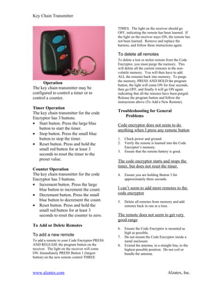
Key Chain Transmitter

                                                TIMES. The light on the receiver should go
                                                OFF, indicating the remote has been learned. If
                                                the light on the receiver stays ON, the remote has
                                                not been learned. Remove and replace the
                                                harness, and follow these instructions again.

                                                To delete all remotes
                                                To delete a lost or stolen remote from the Code
                                                Encryptor, you must purge the memory. This
                                                will delete all the current remotes in the non-
                                                volatile memory. You will then have to add
                                                ALL the remotes back into memory. To purge
                                                the memory, PRESS AND HOLD the program
      Operation                                 button, the light will come ON for four seconds,
The key chain transmitter may be                then go OFF, and finally it will go ON again
configured to control a timer or to             indicating that all the remotes have been purged.
control a counter.                              Release the program button and follow the
                                                instructions above (To Add a New Remote).
Timer Operation
The key chain transmitter for the code          Troubleshooting for General
Encryptor has 3 buttons.                           Problems
• Start button. Press the large blue            Code encryptor does not seem to do
   button to start the timer.                   anything when I press any remote button
• Stop button. Press the small blue
   button to stop the timer.                    1.   Check power and ground.
• Reset button. Press and hold the              2.   Verify the remote is learned into the Code
                                                     Encryptor’s memory.
   small red button for at least 3              3.   Ensure that the remote battery is good.
   seconds to reset the timer to the
   preset value.                                The code encryptor starts and stops the
                                                timer, but does not reset the timer.
Counter Operation
The key chain transmitter for the code          4.   Ensure you are holding Button 3 for
Encryptor has 3 buttons.                             approximately three seconds.
• Increment button. Press the large
   blue button to increment the count.          I can’t seem to add more remotes to the
• Decrement button. Press the small             code encryptor
   blue button to decrement the count.          5.   Delete all remotes from memory and add
• Reset button. Press and hold the                   remotes back in one at a time.
   small red button for at least 3
   seconds to reset the counter to zero.        The remote does not seem to get very
                                                good range
To Add or Delete Remotes
                                                6.   Ensure the Code Encryptor is mounted as
                                                     high as possible.
To add a new remote                             7.   Do not mount the Code Encryptor inside a
To add a remote to your Code Encryptor PRESS         metal enclosure.
AND RELEASE the program button on the           8.   Extend the antenna, in a straight line, to the
receiver. The light on the receiver will come        highest possible position. Do not coil or
ON. Immediately PRESS Button 1 (largest              bundle the antenna.
button) on the new remote control THREE


www.alzatex.com                                                                     Alzatex, Inc.
Key Chain Transmitter


Technical Information                                               equipment unless authorized by the installation instructions
                                                                    or User’s Manual. Unauthorized changes or modifications
                                                                    could void the user's authority to operate the equipment.
Channel 3 Output (red button)
The Code Encryptor provides the ability to
reconfigure Channel 3 to a variety of popular                       Canadian Department of
outputs using the on board jumpers.                                      Communications (DOC)
Output/jumper configuration is as follows:                               Statement
Both jumpers in                Momentary output                     NOTICE: The Canadian Department of Communications
(default)                                                           label identifies certified equipment. This certification means
                                                                    that the equipment meets certain telecommunications
Jumper closest to the          Latching (on/off) output             network protective, operational and safety requirements. The
harness removed                                                     Department does not guarantee the equipment will operate to
Jumper farthest from           75 second timed output               the user's satisfaction. Before installing the equipment, users
the harness removed                                                 should ensure that it is permissible to be connected to the
                                                                    facilities of the local telecommunications company. The
Both jumpers out               150 second timed                     equipment must also be installed using an acceptable method
                               output                               of connection. In some cases, the company’s inside wiring
                                                                    associated with a single line individual service may be
                                                                    extended by means of certified connector assembly
Outputs 1 and 2 are dry contact closures. Output                    (telephone extension cord). The customer should be aware
3 is a 12VDC/500ma (-) transistor output.                           that compliance with the above conditions may not prevent
                                                                    degradation of service in some situations.

                                                                    Repairs to certified equipment should be made by an
Federal Communications                                              authorized Canadian maintenance facility designed by the
      Commission (FCC) Statement                                    supplier. Any repairs or alterations made by the user of this
                                                                    equipment, or equipment malfunctions may give the
                                                                    telecommunications company cause to request the user to
This equipment has been tested to FCC requirements and has          disconnect the equipment.
been found acceptable for use. The FCC requires the
following statement for your information.                           User’s should ensure for their own protection that the
                                                                    electrical ground connections of the power utility, telephone
This equipment generates and uses radio frequency energy            lines and internal metallic water pipe system, if present, are
and if not installed and used properly, that is, in strict          connected together. This precaution may be particularly
accordance with the manufacturer’s instructions, may cause          important to rural areas.
interference to radio and television reception. It has been type
tested and been found to comply with the limits for a Class B       CAUTION: User should not attempt to make such
computing device in accordance with the specifications in           connections themselves, but should contact the appropriate
Part 15 of FCC Rules, which are designed to provide                 electric inspection authority, or electrician, as appropriate.
reasonable protection against such interference in a
residential installation. However, there is no guarantee that       The Load Number (LN) assigned to each terminal device
interference will not occur in a particular installation. If this   denotes the percentage of the total load to be connected to a
equipment does cause interference to radio or television            telephone loop which is used by the device, to prevent
reception, which can be determined by turning the equipment         overloading. The termination on a loop may consist of any
off and on, the user is encouraged to try to correct the            combination of devices subject only to the requirement that
interference by one or more of the following measures:              the total of the Load Numbers of all of the devices does not
•     If using an indoor antenna, have a quality outdoor            exceed 100.
      antenna installed.
•     Reorient the receiving antenna until interference is
      reduced or eliminated.
                                                                    Specifications
•     Move the receiver away from the
      control/communicator.                                         Receiver
•     Move the antenna leads away from any wire runs to the
      control/communicator.                                         •    Power: 12VDC input
•     Plug the control/communicator into a different outlet so      •    Frequency: 303MHz
      that it and the receiver are on different branch circuits.    •    Standby power consumption: 15ma
                                                                    •    Temperature range: -5 to 160 deg F
If necessary the user should consult the dealer or an
experienced radio/television technician for additional
suggestions.
                                                                    Remote Control
                                                                    •    Range: 150+ feet
The user or installer may find the following booklets               •    Battery: 12VDC mini (GP23A) Replace battery at least
prepared by the Federal Communications Commission                        once per year.
helpful: “Interference Handbook”. This booklet is available
from the U.S. Government Office, Washington, DC 20402.
The user shall not make any changes or modifications to the


www.alzatex.com                                                                                                 Alzatex, Inc.

Code Encryptor Um

  • 1.
    Key Chain Transmitter TIMES. The light on the receiver should go OFF, indicating the remote has been learned. If the light on the receiver stays ON, the remote has not been learned. Remove and replace the harness, and follow these instructions again. To delete all remotes To delete a lost or stolen remote from the Code Encryptor, you must purge the memory. This will delete all the current remotes in the non- volatile memory. You will then have to add ALL the remotes back into memory. To purge the memory, PRESS AND HOLD the program Operation button, the light will come ON for four seconds, The key chain transmitter may be then go OFF, and finally it will go ON again configured to control a timer or to indicating that all the remotes have been purged. control a counter. Release the program button and follow the instructions above (To Add a New Remote). Timer Operation The key chain transmitter for the code Troubleshooting for General Encryptor has 3 buttons. Problems • Start button. Press the large blue Code encryptor does not seem to do button to start the timer. anything when I press any remote button • Stop button. Press the small blue button to stop the timer. 1. Check power and ground. • Reset button. Press and hold the 2. Verify the remote is learned into the Code Encryptor’s memory. small red button for at least 3 3. Ensure that the remote battery is good. seconds to reset the timer to the preset value. The code encryptor starts and stops the timer, but does not reset the timer. Counter Operation The key chain transmitter for the code 4. Ensure you are holding Button 3 for Encryptor has 3 buttons. approximately three seconds. • Increment button. Press the large blue button to increment the count. I can’t seem to add more remotes to the • Decrement button. Press the small code encryptor blue button to decrement the count. 5. Delete all remotes from memory and add • Reset button. Press and hold the remotes back in one at a time. small red button for at least 3 seconds to reset the counter to zero. The remote does not seem to get very good range To Add or Delete Remotes 6. Ensure the Code Encryptor is mounted as high as possible. To add a new remote 7. Do not mount the Code Encryptor inside a To add a remote to your Code Encryptor PRESS metal enclosure. AND RELEASE the program button on the 8. Extend the antenna, in a straight line, to the receiver. The light on the receiver will come highest possible position. Do not coil or ON. Immediately PRESS Button 1 (largest bundle the antenna. button) on the new remote control THREE www.alzatex.com Alzatex, Inc.
  • 2.
    Key Chain Transmitter TechnicalInformation equipment unless authorized by the installation instructions or User’s Manual. Unauthorized changes or modifications could void the user's authority to operate the equipment. Channel 3 Output (red button) The Code Encryptor provides the ability to reconfigure Channel 3 to a variety of popular Canadian Department of outputs using the on board jumpers. Communications (DOC) Output/jumper configuration is as follows: Statement Both jumpers in Momentary output NOTICE: The Canadian Department of Communications (default) label identifies certified equipment. This certification means that the equipment meets certain telecommunications Jumper closest to the Latching (on/off) output network protective, operational and safety requirements. The harness removed Department does not guarantee the equipment will operate to Jumper farthest from 75 second timed output the user's satisfaction. Before installing the equipment, users the harness removed should ensure that it is permissible to be connected to the facilities of the local telecommunications company. The Both jumpers out 150 second timed equipment must also be installed using an acceptable method output of connection. In some cases, the company’s inside wiring associated with a single line individual service may be extended by means of certified connector assembly Outputs 1 and 2 are dry contact closures. Output (telephone extension cord). The customer should be aware 3 is a 12VDC/500ma (-) transistor output. that compliance with the above conditions may not prevent degradation of service in some situations. Repairs to certified equipment should be made by an Federal Communications authorized Canadian maintenance facility designed by the Commission (FCC) Statement supplier. Any repairs or alterations made by the user of this equipment, or equipment malfunctions may give the telecommunications company cause to request the user to This equipment has been tested to FCC requirements and has disconnect the equipment. been found acceptable for use. The FCC requires the following statement for your information. User’s should ensure for their own protection that the electrical ground connections of the power utility, telephone This equipment generates and uses radio frequency energy lines and internal metallic water pipe system, if present, are and if not installed and used properly, that is, in strict connected together. This precaution may be particularly accordance with the manufacturer’s instructions, may cause important to rural areas. interference to radio and television reception. It has been type tested and been found to comply with the limits for a Class B CAUTION: User should not attempt to make such computing device in accordance with the specifications in connections themselves, but should contact the appropriate Part 15 of FCC Rules, which are designed to provide electric inspection authority, or electrician, as appropriate. reasonable protection against such interference in a residential installation. However, there is no guarantee that The Load Number (LN) assigned to each terminal device interference will not occur in a particular installation. If this denotes the percentage of the total load to be connected to a equipment does cause interference to radio or television telephone loop which is used by the device, to prevent reception, which can be determined by turning the equipment overloading. The termination on a loop may consist of any off and on, the user is encouraged to try to correct the combination of devices subject only to the requirement that interference by one or more of the following measures: the total of the Load Numbers of all of the devices does not • If using an indoor antenna, have a quality outdoor exceed 100. antenna installed. • Reorient the receiving antenna until interference is reduced or eliminated. Specifications • Move the receiver away from the control/communicator. Receiver • Move the antenna leads away from any wire runs to the control/communicator. • Power: 12VDC input • Plug the control/communicator into a different outlet so • Frequency: 303MHz that it and the receiver are on different branch circuits. • Standby power consumption: 15ma • Temperature range: -5 to 160 deg F If necessary the user should consult the dealer or an experienced radio/television technician for additional suggestions. Remote Control • Range: 150+ feet The user or installer may find the following booklets • Battery: 12VDC mini (GP23A) Replace battery at least prepared by the Federal Communications Commission once per year. helpful: “Interference Handbook”. This booklet is available from the U.S. Government Office, Washington, DC 20402. The user shall not make any changes or modifications to the www.alzatex.com Alzatex, Inc.